RAYLHR20USHANDHELD MARINE RADIO
Navico Inc.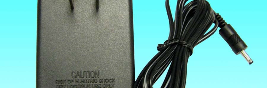
Click to zoom
Application Details
- Equipment Class
- TNF - Licensed Non-Broadcast Transmitter Held to Face
- Date of Grant
- Sep 18, 2007
- Application Purpose
- Original Equipment
- Date of Application
- Sep 17, 2007
- Equipment Note
- HANDHELD MARINE RADIO
- Frequency Range
- 156.02500000 - 157.42500000
- Company
- Navico Inc.
- Country
- United States
Documents & Files
Document Text
Text extracted from the exhibit documents filed with the FCC. Open a document above to read the original.
Users Manual
LHR-20/22 Operation Instructions www.lowrance.com Pub. 988-0158-091 LHR-20 Copyright © 2007 Navico All rights reserved. Lowrance ® is a registered trademark of Navico No part of this manual may be copied, reproduced, republished, transmitted or distributed for any purpose, without prior written consent of Lowrance Electronics. Any unauthorized commercial distribution of this manual is strictly prohibited. Lowrance Electronics may find it necessary to change or end our policies, regulations, and special offers at any time. We reserve the right to do so without notice. All features and specifications subject to change without notice. All screens in this manual are simulated. On the cover: LHR-20/22 shown. Other models covered in the manual are similar. For free owner’s manuals and the most current information on this product, its operation and accessories, visit our web site: www. lowrance.com Lowrance Electronics P.O. Box 669 Catoosa, OK USA 74015 Printed in China. IMPORTANT SAFETY INFORMATION Please read carefully before installation and use. CAUTION ! ! CAUTION DANGER WARNING This is the safety alert symbol. It is used to alert you to potential personal injury hazards, Obey all safety messages that follow this symbol to avoidpossible injury or death. CAUTION ! ! CAUTION DANGER WARNING WARNING indicates a potentially hazardous situation which, if not avoided, could result in death or serious injury CAUTION ! ! CAUTION DANGER WARNING CAUTION indicates a potentially hazardous situation which, if not avoided, could result in minor or moderate injury. CAUTION ! ! CAUTION DANGER WARNING CAUTION used without the safety alert symbol indicates a potentially hazardous situation which, if not avoided, may result in property damage. Lowrance LHR-20/22 Operation Instructions3 Table of Contents Introduction .............................................................................................................................................4 Safety and Operational Information .........................................................................................................5 Display .....................................................................................................................................................5 Function and Location of the Controls .......................................................................................................6 Before Using Your Radio ...........................................................................................................................7 1. Charging and Installing the Li-ion polymer battery pack . . . . . . . . . . . . . . . . . . . . . . . . . 7 2. Installing the antenna . . . . . . . . . . . . . . . . . . . . . . . . . . . . . . . . . . . . . . . . . . . . . . . . . . . . . . . . . . . 8 3. Installing the belt clip . . . . . . . . . . . . . . . . . . . . . . . . . . . . . . . . . . . . . . . . . . . . . . . . . . . . . . . . . . . 9 Using Your Radio .......................................................................................................................................9 1. Turning the power on/off . . . . . . . . . . . . . . . . . . . . . . . . . . . . . . . . . . . . . . . . . . . . . . . . . . . . . . . 9 2. Adjusting squelch . . . . . . . . . . . . . . . . . . . . . . . . . . . . . . . . . . . . . . . . . . . . . . . . . . . . . . . . . . . . . . 10 3. Transmitting and receiving . . . . . . . . . . . . . . . . . . . . . . . . . . . . . . . . . . . . . . . . . . . . . . . . . . . . . 10 4. Accessing the 16/9 priority channels . . . . . . . . . . . . . . . . . . . . . . . . . . . . . . . . . . . . . . . . . . . 10 5. Selecting channels . . . . . . . . . . . . . . . . . . . . . . . . . . . . . . . . . . . . . . . . . . . . . . . . . . . . . . . . . . . . . 10 6. Selecting high/low power . . . . . . . . . . . . . . . . . . . . . . . . . . . . . . . . . . . . . . . . . . . . . . . . . . . . . . 11 7. Locking the keypad . . . . . . . . . . . . . . . . . . . . . . . . . . . . . . . . . . . . . . . . . . . . . . . . . . . . . . . . . . . . 11 8. Adding channels to memory . . . . . . . . . . . . . . . . . . . . . . . . . . . . . . . . . . . . . . . . . . . . . . . . . . . 11 9. Accessing channels saved to memory . . . . . . . . . . . . . . . . . . . . . . . . . . . . . . . . . . . . . . . . . . 12 10. Scanning . . . . . . . . . . . . . . . . . . . . . . . . . . . . . . . . . . . . . . . . . . . . . . . . . . . . . . . . . . . . . . . . . . . . . . . 12 11. Using the WATCH modes . . . . . . . . . . . . . . . . . . . . . . . . . . . . . . . . . . . . . . . . . . . . . . . . . . . . . . . 13 12. Selecting a WX (weather) channel . . . . . . . . . . . . . . . . . . . . . . . . . . . . . . . . . . . . . . . . . . . . . . 13 13. Weather Alert Operation . . . . . . . . . . . . . . . . . . . . . . . . . . . . . . . . . . . . . . . . . . . . . . . . . . . . . . . 14 14. Selecting the U.S./International/Canadian band . . . . . . . . . . . . . . . . . . . . . . . . . . . . . . . . 14 15. Resetting the radio . . . . . . . . . . . . . . . . . . . . . . . . . . . . . . . . . . . . . . . . . . . . . . . . . . . . . . . . . . . . . 14 Maintenance ..........................................................................................................................................14 Technical Specifications ..........................................................................................................................15 Frequency Charts ....................................................................................................................................16 FCC Compliance ...................................................................................................................................23 Lowrance Warranty ................................................................................................................................24 How to Obtain Service .....................…
Text truncated - open the document above for the full version.
Cover Letter(s)
Navman NZ Ltd. 13 – 17 Kawana Street Northcote Auckland New Zealand September 10, 2007 Federal Communications Commission Authorization and Evaluation Division Confidentiality Request regarding application for certification of FCC ID: RAYLHR20 Pursuant to Sections 0.457 and 0.459 of the Commission’s Rules, we hereby request confidential treatment of information accompanying this application as outlined below: Exhibits Description Exhibits Name.extension Block Diagram LHR20, 22, EHR10 Block Diagram-A.pdf Schematics LHR20, 22, EHR10 Main Schematic Diagram-A.pdf Schematics EHR10 Battery Schematics Diagram-A.pdf Schematics LHR20, 22 Charger Schematic Diagram-A.pdf Circuit Description LHR20, 22, EHR10 theory of operation.pdf Parts List LHR20 BOM.pdf Tune Up Procedure LHR20 Function of Devices. pdf The above materials contain trade secrets and proprietary information not customarily released to the public. The public disclosure of these materials may be harmful to the applicant and provide unjustified benefits to its competitors. Pursuant to DA 04-1705 June 15, 2004 of the Commission’s public notice, we also request temporary confidential treatment of information accompanying this application as outlined below: Exhibits Description Exhibits Name.extension Test Setup Photos 2874AUT7 Test Setup.pdf External Photos 2874AUT7 Ext Photos.pdf Internal Photos 2874AUT7 Int Photos.pdf Users Manual LHR-20_22.pdf Users Manual 9880158081_HER-10_Operation.pdf Sincerely, Don Korte On behalf of Navman
External Photos
External Photos LHR20 Front View LHR20 Bottom View LHR20 Adapter – Front View LHR20 Adapter – Rear View LHR20 Charger – Front View LHR20 Charger – Rear View LHR20 Charger Side View EHR10 Front View EHR10 Rear View EHR10 Adapter – Front View EHR10 Adapter – Rear View
ID Label/Location Info
Proposed Location – Battery Compartment of DUT Label Here
ID Label/Location Info
Nazman NZ Ltd. September 11, 2007 Equipment Authorization Division Office of Engineering and Technology Federal Communications Commission Industrial Canada Certificate Bureau Ref: FCC ID: RAYLHR20US, IC: 4697A0-LHR20U Label Justification Dear Sirs: The applicant requests acceptance of the labeling proposal described below for transmitters bearing FCC identifier RAYLHR20US. The subject transmitters are handheld marine radio lower power radio models as shown in “external photos” exhibit authorized under 47CFR Pt 80. Because the majority of the transmitters housing is composed of touching area, LCD display, and a removable battery pack, there is extremely limited space available to attach the required label carrying the FCC identifier. Attaching the label to the battery pack is not acceptable because the battery pack is a removable item. For this reason, we proposes placing the label carrying the FCC identifier inside the battery compartment as shown in “ID Label Proposed Location” exhibit. The consumer packaging for these models includes the battery pack as a separate item, NOT installed on the radio. As such, the FCC identifier will be readily visible to the user before the battery pack is installed and whenever the battery pack is removed or replaced. In this location, the label will also be protected from physical abuse and remain readable for the anticipated life of the device. The consumer packaging for these models is a "carbon box" which does not allow the transmitters to be seen at time of purchase. In order to meet the requirements of 47CFR Part 2.925 (d), we will add the FCC identifier "RAYLHR20US" and IC:4697A-LHR20U to the outside of the consumer "carbon box" packaging. Sincerely, Don Korte On behalf of Navman NZ Ltd.
Internal Photos
Internal Photos LHR20, EHR10, LHR22 Main Board with – Bottom with Shield LHR20, EHR10, LHR22 Main Board with – Bottom without Shield LHR20, EHR10, LHR22 Main Board – Top with Display On LHR20, EHR10, LHR22 Main Board – Top with Display Removed LHR20 Assembly – Bottom LHR20 Charger Bottom View LHR20 Charger Top View EHR10 Assembly Bottom
Operational Description
EHR-10 Operation Instructions www.eaglesonar.com Pub. 988-0158-081 Copyright © 2007 Navico All rights reserved. Eagle® is a registered trademark of Navico No part of this manual may be copied, reproduced, republished, transmitted or distributed for any purpose, without prior written consent of Eagle Electronics. Any unauthorized commercial distribution of this manual is strictly prohibited. Eagle Electronics may find it necessary to change or end our policies, regulations, and special offers at any time. We reserve the right to do so without notice. All features and specifications subject to change without notice. All screens in this manual are simulated. On the cover: EHR-10 shown. Other models covered in the manual are similar. For free owner’s manuals and the most current information on this product, its operation and accessories, visit our web site: www.eaglesonar.com Eagle Electronics P.O. Box 669 Catoosa, OK USA 74015 Printed in China. IMPORTANT SAFETY INFORMATION Please read carefully before installation and use. CAUTION ! ! CAUTION DANGER WARNING This is the safety alert symbol. It is used to alert you to potential personal injury hazards, Obey all safety messages that follow this symbol to avoidpossible injury or death. CAUTION ! ! CAUTION DANGER WARNING WARNING indicates a potentially hazardous situation which, if not avoided, could result in death or serious injury CAUTION ! ! CAUTION DANGER WARNING CAUTION indicates a potentially hazardous situation which, if not avoided, could result in minor or moderate injury. CAUTION ! ! CAUTION DANGER WARNING CAUTION used without the safety alert symbol indicates a potentially hazardous situation which, if not avoided, may result in property damage. EAGLE EHR-10 Operation Instructions3 Table of Contents Introduction .............................................................................................................................................4 Safety and Operational Information .........................................................................................................5 Display .....................................................................................................................................................5 Function and Location of the Controls .......................................................................................................6 Before Using Your Radio ...........................................................................................................................7 1. Charging and Installing the Ni-MH battery pack . . . . . . . . . . . . . . . . . . . . . . . . . . . . . . . . . 7 2. Installing the antenna . . . . . . . . . . . . . . . . . . . . . . . . . . . . . . . . . . . . . . . . . . . . . . . . . . . . . . . . . . . 8 3. Installing the belt clip . . . . . . . . . . . . . . . . . . . . . . . . . . . . . . . . . . . . . . . . . . . . . . . . . . . . . . . . . . . 8 Using Your Radio .......................................................................................................................................9 1. Turning the power on/off . . . . . . . . . . . . . . . . . . . . . . . . . . . . . . . . . . . . . . . . . . . . . . . . . . . . . . . 9 2. Adjusting squelch . . . . . . . . . . . . . . . . . . . . . . . . . . . . . . . . . . . . . . . . . . . . . . . . . . . . . . . . . . . . . . . 9 3. Transmitting and receiving . . . . . . . . . . . . . . . . . . . . . . . . . . . . . . . . . . . . . . . . . . . . . . . . . . . . . 10 4. Accessing the 16/9 priority channels . . . . . . . . . . . . . . . . . . . . . . . . . . . . . . . . . . . . . . . . . . . 10 5. Selecting channels . . . . . . . . . . . . . . . . . . . . . . . . . . . . . . . . . . . . . . . . . . . . . . . . . . . . . . . . . . . . . 10 6. Selecting high/low power . . . . . . . . . . . . . . . . . . . . . . . . . . . . . . . . . . . . . . . . . . . . . . . . . . . . . . 10 7. Locking the keypad . . . . . . . . . . . . . . . . . . . . . . . . . . . . . . . . . . . . . . . . . . . . . . . . . . . . . . . . . . . . 11 8. Adding channels to memory . . . . . . . . . . . . . . . . . . . . . . . . . . . . . . . . . . . . . . . . . . . . . . . . . . . 11 9. Accessing channels saved to memory . . . . . . . . . . . . . . . . . . . . . . . . . . . . . . . . . . . . . . . . . . 11 10. Scanning . . . . . . . . . . . . . . . . . . . . . . . . . . . . . . . . . . . . . . . . . . . . . . . . . . . . . . . . . . . . . . . . . . . . . . . 12 11. Using the WATCH modes . . . . . . . . . . . . . . . . . . . . . . . . . . . . . . . . . . . . . . . . . . . . . . . . . . . . . . . 12 12. Selecting a WX (weather) channel . . . . . . . . . . . . . . . . . . . . . . . . . . . . . . . . . . . . . . . . . . . . . . 13 13. Weather Alert Operation . . . . . . . . . . . . . . . . . . . . . . . . . . . . . . . . . . . . . . . . . . . . . . . . . . . . . . . 13 14. Selecting the U.S./International/Canadian band . . . . . . . . . . . . . . . . . . . . . . . . . . . . . . . . 13 15. Resetting the radio . . . . . . . . . . . . . . . . . . . . . . . . . . . . . . . . . . . . . . . . . . . . . . . . . . . . . . . . . . . . . 14 Maintenance ..........................................................................................................................................14 Technical Specifications ..........................................................................................................................15 Frequency Charts ....................................................................................................................................16 FCC Compliance ...................................................................................................................................23 Eagle Warranty .......................................................................................................................................24 How to Obtain Service ......................................…
Text truncated - open the document above for the full version.
Test Report
HANDHELD MARINE RADIO PER FCC PT 80 & IC RSS-182 TEST REPORT APPLICANT Navman NZ Ltd. ADDRESS 13-17 Kawana Street Northcote Auckland New Zealand FCC ID RAYLHR20US IC LABEL IC: 4697A-LHR20U TESTED MODEL LHR-20U FAMILY MODEL(S) EHR-10U, LHR-22U PRODUCT DESCRIPTION Handheld Marine Radio DATE SAMPLE RECEIVED August 21, 2007 DATE TESTED August 24,2 007 TESTED BY Nam Nguyen APPROVED BY Mario de Aranzeta TIMCO REPORT NO. 2874AUT7TestReport.PDF TEST RESULTS PASS FAIL THE ATTACHED REPORT SHALL NOT BE REPRODUCED EXCEPT IN FULL WITHOUT THE WRITTEN APPROVAL OF TIMCO ENGINEERING, INC. 849 NW STATE ROAD 45 NEWBERRY, FL 32669 USA PH: 888.472.2424 OR 352.472.5500 FAX: 352.472.2030 EMAIL: [email protected] HTTP: //WWW.TIMCOENGR.COM Certificate # 0955-01 Applicant: Navman NZ Ltd. FCC ID: RAYLHR20US, IC: 4697A-LHR20U Report: W:\N\NAVMAN NZ_RAY\2874AUT7\2874AUT7TestReport.doc Page 2 of 28 TABLE OF CONTENTS ATTESTATION................................................................................................. 3 REPORT SUMMARY ........................................................................................ 4 TEST ENVIRONMENT AND TEST SETUP......................................................... 4 DUT DESCRIPTION......................................................................................... 5 TECHNICAL SUMMARY .................................................................................. 6 TEST EQUIPMENT .......................................................................................... 8 TEST PROCEDURE ......................................................................................... 9 TEST RESULT............................................................................................... 11 RF POWER OUTPUT ........................................................................................................... 11 MODULATION CHARACTERISTICS..................................................................................... 12 OCCUPIED BANDWIDTH .................................................................................................... 15 SPURIOUS EMISSIONS AT ANTENNA TERMINALS (CONDUCTED) ..................................... 16 FIELD STRENGTH OF SPURIOUS EMISSIONS (RADIATED)................................................ 17 RECEIVER RADIO INTERFERENCE.................................................................................... 18 FREQUENCY STABILITY..................................................................................................... 20 POWER LINE CONDUCTED INTERFERENCE ..................................................................... 21 Applicant: Navman NZ Ltd. FCC ID: RAYLHR20US, IC: 4697A-LHR20U Report: W:\N\NAVMAN NZ_RAY\2874AUT7\2874AUT7TestReport.doc Page 3 of 28 ATTESTATION This equipment has been tested in accordance with the standards identified in the referenced test report. To the best of my knowledge and belief, these tests were performed using the measurement procedures described in this report. Certificate #0955-01 All instrumentation and accessories used to test products for compliance to the indicated standards are calibrated regularly in accordance with ISO 17025 requirements. I attest that the necessary measurements were made by me or under my supervision, at Timco Engineering, Inc. located at 849 N.W. State Road 45, Newberry, Florida 32669 USA. Authorized by: Mario de Aranzeta Signature: On File Function: Test Lab Supervisor / Engineer Date: September 4, 2007 Applicant: Navman NZ Ltd. FCC ID: RAYLHR20US, IC: 4697A-LHR20U Report: W:\N\NAVMAN NZ_RAY\2874AUT7\2874AUT7TestReport.doc Page 4 of 28 REPORT SUMMARY Disclaimer The test results relate only to the items tested. Purpose of Test To show the DUT in compliance with FCC CFR 47 Part 80 and Industry Canada RSS-182 requirements for handheld marine radio. Test Procedures ANSI/TIA 603-C: 2004, FCC CFR 47 Part 80, ANSI C63.4: 2003 IC RSS-182 Related Approval(s)/ Report(s) N/A TEST ENVIRONMENT AND TEST SETUP Test Facility All tests were conducted by Timco Engineering Inc. located at 849 NW State Road 45, Newberry, FL 32669 USA Laboratory Test Condition Temperature: 26ºC Relative humidity: 50%. Deviation from the standards No deviation Modification to the DUT No modification was made. Test Exercise (software etc.) The DUT was placed in continuous transmitting mode of operation. System Setup No testing accessories. The DUT is a stand alone device. Applicant: Navman NZ Ltd. FCC ID: RAYLHR20US, IC: 4697A-LHR20U Report: W:\N\NAVMAN NZ_RAY\2874AUT7\2874AUT7TestReport.doc Page 5 of 28 DUT DESCRIPTION Manufactured by Navman NZ Ltd. Product Description Handheld Marine Radio FCC ID RAYLHR20US IC Label IC: 4697A-LHR20U M/N LHR-20U (representing the worst-case scenario) Family M/Ns HER-10U, LHR-22U Trade Name Lowrance for LHR-20U and LHR-22U Eagle for EHR-10U S/N 20070816001 Model Variance LHR-20U and EHR-10U are the exactly same except the power supplies. LHR-20U uses Li-ion re-chargeable battery. There is protection circuit inside the Li-ion battery. EHR-10U uses Ni-MH battery pack; and the charger circuit is on the small PCB board connected to the Ni-MH battery pack, i.e., inside the AA tray. One poly fuse is supplied with Ni-MH battery pack. LHR-22U is exactly same as LHR20 except color of the enclosure. Power Source LHR-20U: DC12V 800mA EHR-10U: DC12V 200mA Test Accessories LHR-20U: AC/DC Adaptor Class 2 m/n: PI-41-691US (Input: 120Vac 60 Hz 19W, Output: 12V DC 800mA) EHR-10U: Plug-in Power Supply, m/n: PI-35-24D (Input: AC120V 60 Hz 5W, Output: 12V DC 200mA) Test Item Preproduction Type of DUT Portable Applicant: Navman NZ Ltd. FCC ID: RAYLHR20US, IC: 4697A-LHR20U Report: W:\N\NAVMAN NZ_RAY\2874AUT7\2874AUT7TestReport.doc Page 6 of 28 TECHNICAL SUMMARY FCC Rule Part IC Rule Part Item Description Pt 2.1033(c) (6) RSS-182 Operating Frequency 156.025 ~ 157.425 MHz Pt 80.205 (a) RSS-182 Occupied Bandwidth 16 kHz Pt 2.1033(c)(7) RSS-182 Power Range and Controls There is a u…
Text truncated - open the document above for the full version.
Test Setup Photos
Test setup Photos Spurious Emission Emissions Radio Interference Conducted Emissions – LHR20 Conducted Emissions – EHR10
Contact Information
Applicant
Filippo Campolmi(Regulatory Compliance Manager)
Test Firm
Timco Engineering, Inc.Sid Sanders
Technical Specifications
| # | Rule Parts | Frequency Range | Power Output | Emission | Tolerance |
|---|---|---|---|---|---|
| 2 | 8 | 156.025 MHz - 157.425 MHz | 1 W | 16K0G3E | 10 ppm |
Other Applications from Navico Inc.

RAYVHFNRS2A
Aug 11, 2021MARINE BLACK BOX DSC/AIS VHF RADIO SYSTEM
Equipment Class
DTS - Digital Transmission System
RAYVHFNRS1A
May 18, 2021MARINE BLACK BOX DSC/AIS VHF RADIO SYSTEM
Equipment Class
DTS - Digital Transmission System
RAYVHFNRS2
Nov 30, 2020MARINE BLACK BOX DSC/AIS VHF RADIO SYSTEM
Equipment Class
JAB - Part 15 Class B Digital Device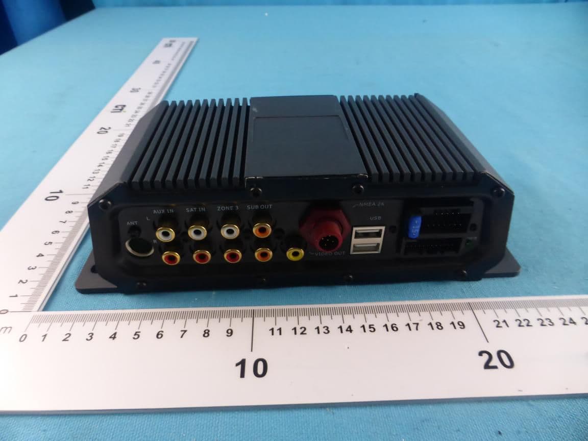
RAYSHGEN2
Sep 17, 2015Marine Entertainment System
Equipment Class
DTS - Digital Transmission System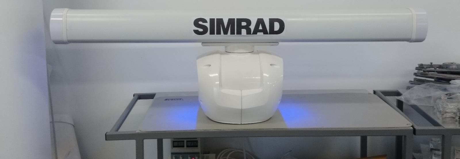
RAYHALO
Apr 09, 2015HALO PULSE COMPRESSION MARINE RADAR
Equipment Class
MRD - Marine Radar