RCXEE11ABG51xWLAN SED
Ixia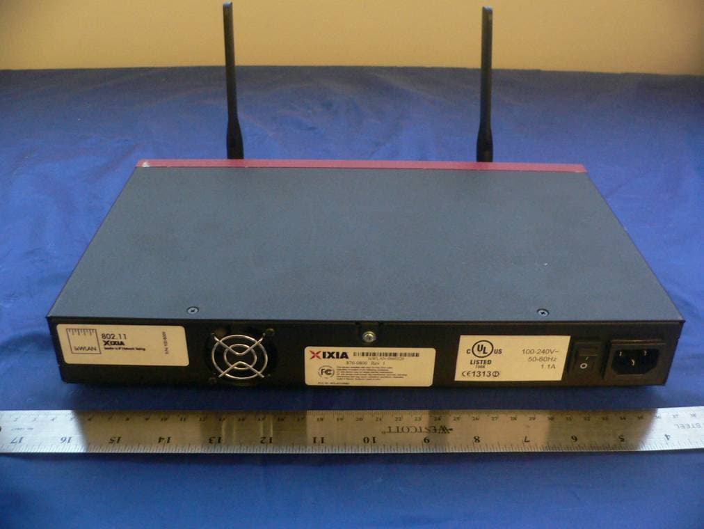
Click to zoom
Application Details
- Equipment Class
- NII - Unlicensed National Information Infrastructure TX
- Date of Grant
- Jan 02, 2008
- Application Purpose
- Original Equipment
- Date of Application
- Jan 02, 2008
- Equipment Note
- 1xWLAN SED
- Frequency Range
- 5470.00000000 - 5725.00000000
- Company
- Ixia
- Country
- United States
Documents & Files
Document Text
Text extracted from the exhibit documents filed with the FCC. Open a document above to read the original.
Users Manual
IxWLAN ™ User Guide Release 6.20 Part No. 913-0073-03 Rev A May 2007 iiIxWLAN User Guide, Release 6.20 Copyright © 2007 Ixia. All rights reserved. This publication may not be copied, in whole or in part, without Ixia’s consent. RESTRICTED RIGHTS LEGEND: Use, duplication, or disclosure by the U.S. Government is subject to the restrictions set forth in subparagraph (c)(1)(ii) of the Rights in Technical Data and Computer Software clause at DFARS 252.227-7013 and FAR 52.227- 19. Ixia, the Ixia logo, and all Ixia brand names and product names in this document are either trademarks or registered trademarks of Ixia in the United States and/or other countries. All other trademarks belong to their respective owners. The information herein is furnished for informational use only, is subject to change by Ixia without notice, and should not be con- strued as a commitment by Ixia. Ixia assumes no responsibility or liability for any errors or inaccuracies contained in this publica- tion. Part No. 913-0073-03 Rev A May 14, 2007 Corporate Headquarters Ixia Worldwide Headquarters 26601 W. Agoura Rd. Calabasas, CA 91302 USA +1 877 FOR IXIA (877 367 4942) +1 818 871 1800 (International) (FAX) +1 818 871 1805 [email protected] Web site: www.ixiacom.com General: [email protected] Investor Relations: [email protected] Training: [email protected] Support: [email protected] +1 877 367 4942 EMEA Ixia Europe Limited Globeside Business Park Building One, Unit A Marlow, SL7 1GJ United Kingdom +44 1869 356370 (FAX) +44 1869 356371 [email protected] Support: [email protected] +44 1869 356370 (Option 5) Asia Pacific Asia Pacific Representative Office New Shanghai International Tower, Suite 26E 360 Pudong Nan Rd Shanghai 200120 China +86 21 50543439 [email protected] Support: [email protected] +1 818 871 1800 (Option 1) Japan Ixia KK Aioi Sampo Shinjuku Building, 16th Floor 3-25-3 Yoyogi Shibuya-Ku Tokyo 151-0053 Japan +81 3 5365 4690 (FAX) +81 3 3299 6263 [email protected] Support: [email protected] +1 818 871 1800 (Option 1) India Ixia India No. 508, 6th Main 6th Cross ST Bed, Koramangala 4th Block Bangalore 560 034 India +91 80 25633570 (FAX) +91 80 25633487 [email protected] Support: [email protected] +91 80 32918500 IxWLAN User Guide, Release 6.20iii Table of Contents Chapter 1Introduction Introduction to IxWLAN. . . . . . . . . . . . . . . . . . . . . . . . . . . . . 1-1 Packaging Checklist . . . . . . . . . . . . . . . . . . . . . . . . . . . . . . . 1-3 Features . . . . . . . . . . . . . . . . . . . . . . . . . . . . . . . . . . . . . . . . 1-4 WPA/RSN . . . . . . . . . . . . . . . . . . . . . . . . . . . . . . . . . . . . . . . 1-6 Files. . . . . . . . . . . . . . . . . . . . . . . . . . . . . . . . . . . . . . . . . . . . 1-8 System Needs. . . . . . . . . . . . . . . . . . . . . . . . . . . . . . . . . . . 1-10 Hardware Characteristics . . . . . . . . . . . . . . . . . . . . . . . . . . 1-10 General Usage Notes . . . . . . . . . . . . . . . . . . . . . . . . . . . . . 1-12 Feature Key Dependent Parameters. . . . . . . . . . . . . . . . . . 1-13 Chapter 2Installation Attaching the Antennas. . . . . . . . . . . . . . . . . . . . . . . . . . . . . 2-1 Table of Contents ivIxWLAN User Guide, Release 6.20 Connecting Directly to a Command PC. . . . . . . . . . . . . . . . 2-2 Connecting Through an Ethernet Hub or Switch. . . . . . . . . 2-3 Connecting to the Serial Port. . . . . . . . . . . . . . . . . . . . . . . . 2-3 Chapter 3First Setup Using the Ethernet Ports . . . . . . . . . . . . . . . . . . . . . . . . . . . 3-1 Using the Serial Port . . . . . . . . . . . . . . . . . . . . . . . . . . . . . . 3-5 Chapter 4The Web-Based User Interface Startup and Login. . . . . . . . . . . . . . . . . . . . . . . . . . . . . . . . . 4-1 Choosing and Creating a Scenario . . . . . . . . . . . . . . . . . . . 4-3 Using the Main Page . . . . . . . . . . . . . . . . . . . . . . . . . . . . . 4-14 vSTA Side Bar . . . . . . . . . . . . . . . . . . . . . . . . . . . . . . . . . . 4-25 IxWLAN Side Bar. . . . . . . . . . . . . . . . . . . . . . . . . . . . . . . . 4-40 Monitors Side Bar . . . . . . . . . . . . . . . . . . . . . . . . . . . . . . . 4-55 Event Log Side Bar . . . . . . . . . . . . . . . . . . . . . . . . . . . . . . 4-63 Reports Side Bar . . . . . . . . . . . . . . . . . . . . . . . . . . . . . . . . 4-66 Configuration Side Bar. . . . . . . . . . . . . . . . . . . . . . . . . . . . 4-71 Menus and Tool Bars. . . . . . . . . . . . . . . . . . . . . . . . . . . . . 4-78 IxWLAN User Guide, Release 6.20v Table of Contents Chapter 5The Command Line Interface (CLI) CLI Usage Notes. . . . . . . . . . . . . . . . . . . . . . . . . . . . . . . . . . 5-3 User Login. . . . . . . . . . . . . . . . . . . . . . . . . . . . . . . . . . . . . . . 5-3 User Logoff . . . . . . . . . . . . . . . . . . . . . . . . . . . . . . . . . . . . . . 5-4 CLI Commands. . . . . . . . . . . . . . . . . . . . . . . . . . . . . . . . . . . 5-4 System Under Test Commands. . . . . . . . . . . . . . . . . . . . . . . 5-7 Virtual Station Setup and Control Commands. . . . . . . . . . . 5-14 Statistics File Commands . . . . . . . . . . . . . . . . . . . . . . . . . . 5-52 Event Log Commands. . . . . . . . . . . . . . . . . . . . . . . . . . . . . 5-54 IxWLAN Commands . . . . . . . . . . . . . . . . . . . . . . . . . . . . . . 5-59 802.11b/g Commands. . . . . . . . . . . . . . . . . . . . . . . . . . . . . 5-87 Administrative Mode Commands . . . . . . . . . . . . . . . . . . . . 5-91 Example Configurations . . . . . . . . . . . . . . . . . . . . . . . . . . . 5-98 CLI Editor . . . . . . . . . . . . . . . . . . . . . . . . . . . . . . . . . . . . . 5-115 Chapter 6The Programming Interface (Perl) Chapter 7Statistics Counters Individual Virtual Station Counters . . . . . . . . . . . . . . . . . . . . 7-1 Summary Statistics . . . . . . . . . . . . . . . . . . . . . . . . . . . . . . . . 7-7 Table of Contents viIxWLAN User Guide, R…
Text truncated - open the document above for the full version.
Users Manual
IxWLAN User Guide, Release 6.205-23 The Command Line Interface (CLI) Virtual Station Setup and Control Commands Cipher .................... WEP(RC4) Data Encryption ........... Off Shared-key Index .......... 0 Fragmentation Threshold ... 2346 RTS Threshold ............. 2346 Mode ...................... internal Layer .................. 3 Load Application .......... ping Target IP Address ......... 10.1.83.1 Ping Transmit Count ....... 100 Ping Data Size ............ 1024 autorunAutomatically runs one or more configured virtual stations that are in the ready state. It is intended for use in conjunction with the autoconf command. Any other use may produce unexpected results.The command issues the run com- mand for the specified number of virtual stations. autorun [nVstas] [nVstas]: Optional number of virtual stations (1...128). If this parameter is omit- ted, the total number of auto-configured (autoconf) virtual stations is used. clear groupClears the certfile, SSID, or statistics for the specified vSTA or all vSTAs within the specified group. clear group <grpID> <object> Valid objects are: <certfile>: Clears vSTA group certfile names. <SSID>: Clears vSTA group SSIDs. <stats>: Clears vSTA group statistics. clear vstaClears all statistics for one or more virtual stations. clear vsta <vStaId>:all:master:<object> <vStaId>: Virtual Station ID (1...128), all, or master. If <vStaId> is set to all (that is, clear vsta all stats), this command clears all statistics for all virtual sta- tions. If <vStaId> is set to master (that is, clear vsta master stats), this command clears all statistics for IxWLAN. NOTE: By default, all virtual stations that are created in the CLI are assigned to group 1. This can be changed using the set vsta <vStaId> group <grpId> command. The Command Line Interface (CLI) Virtual Station Setup and Control Commands 5-24IxWLAN User Guide, Release 6.20 5 Example: [wport1]IxWLAN -> clear vsta 1 stats [wport1]IxWLAN -> Valid objects are: <certfile>: Clears vSTA certfile names. <SSID>: Clears vSTA SSIDs. <stats>: Clears vSTA statistics. confConfigures a virtual station. It specifies a virtual station's IP address, WLAN MAC address, and load application mode. It also specifies the load application protocol, target host, and application specific parameters. After a virtual station is configured, it must be initialized using the init command. The virtual station’s wport attribute defaults to the current wport. conf <vStaId> <ip|dhcp_value> <mac> <mode> <lp> <targetIP> <count> <size> <vStaId>: Virtual Station ID (1...128) <ip|dhcp_value>: Specifies the virtual station’s WLAN IP address (nnn.nnn.nnn.nnn) or a <dhcp_value>. <dhcp_value> can be on, off, or auto. on = manual (needs the acquireip command to start), off = DHCP is not active. vSTA(s) must have a static IP address, auto = initiate lease negotiation if associa- tion succeeds. <mac>: Virtual station’s WLAN MAC address (xx:xx:xx:xx:xx:xx). The starting MAC address must be within the range of MAC addresses defined by the WLAN Base MAC Address and WLAN MAC Mask configured for the specified wport (see set wlanmac on page 5-85 and set wlanmask on page 5-85). <mode>: external or internal. If external mode is used, the remaining parameters (<lp> <target> <count> <size>) are optional. <lp>: Specifies the Load Application Protocol (ping). <targetIP>: Target IP address (nnn.nnn.nnn.nnn) <count>: Number of ICMP Echo Requests to transmit: 0...2,147,483,647. <size>: Number of data bytes to be included in ICMP Echo Requests: 64...1024. The conf command does not include the full set of attributes that can be assigned to a virtual station. When these attributes are not otherwise specified, IxWLAN uses the default values for these attributes, as listed in Table 5-1 on page 5-25. IxWLAN User Guide, Release 6.205-25 The Command Line Interface (CLI) Virtual Station Setup and Control Commands Table 5-1.Attributes AttributeDefault Value authenticationopen-system certfile(not set) cipherwep csmodepersistent dhcplease3600 dhcpretry4 dhcpinterval8 dhcpoffers1 dhcpserver0.0.0.0 eapalgorithmtls encryptionoff fastradiusdisabled fragmentthreshold2346 gateway0.0.0.0 group1 inneralgorithmms-chapv2 ipmask255.255.255.0 keyindex0 (not defined) kmtime-out0 (that is, no time-out) layer3 outeridentity(not set) passphrase(not set) password(not set) pmkcacheenabled psk(not set) retry2 roamtypereassociation rtsthreshold2346 timeout300 SSID(not set) The Command Line Interface (CLI) Virtual Station Setup and Control Commands 5-26IxWLAN User Guide, Release 6.20 5 The set vsta command allows you to change any of these default values. Example: [wport1]IxWLAN -> conf 3 10.1.40.20 00:0b:cd:59:00:01 internal ping 10.1.40.16 64000 1024 [wport1]IxWLAN -> OK [wport1]IxWLAN -> conf 1 10.1.35.150 02:CF:1F:00:00:01 int ping 10.1.35.38 10 1024 [wport1]IxWLAN -> OK [wport1]IxWLAN -> conf 1 on 02:CF:1F:00:00:01 int ping 10.1.35.38 10 1024 [wport1]IxWLAN -> OK [wport1]IxWLAN -> conf 1 auto 02:CF:1F:00:00:01 int ping 10.1.35.38 10 1024 [wport1]IxWLAN -> OK deauthStarts the de-authentication sequence for one or more virtual stations. This sequence also drops any WPA/RSN security associations. The virtual station(s) must be configured, initialized, and authenticated before this command can be used. The following command starts the de-authentication sequence for one or all virtual stations. deauth vsta <vStaId> <vStaId>: Virtual Station ID (1...128) or all. If <vStaId> is set to all (that is, deauth vsta all), the de-authentication sequence is initiated for all virtual stations. The following command starts the de-authentication sequence for all virtual sta- tions in a specified group. deauth group <grpId> <grpId>: Group ID (1...128) Example: [wport1]IxWLAN -> deauth vsta 1 [wport1]IxWLAN -> OK [wport1]IxWLAN -> vSTA ID:1 NOTIFY Operation DEAUTH succeeded - TUE JUL 15 03:09:56 2003 [wport1]IxWLAN -> userid(not set) wport1 AttributeDefault Value NOTE: By default, all virtual stations tha…
Text truncated - open the document above for the full version.
Cover Letter(s)
Date: 2008-01-16 FEDERAL COMMUNICATIONS COMMISSION Authorization and Evaluation Division 7435 Oakland Mills Road Columbia, MD 21046 Subject: Supersede of Test Report R0710244-407 for Ixia FCC ID: RCXEE11ABG5 Bay Area Compliance Laboratories would like to request supersede of the test report exhibit (R0710244-407) for Ixia FCC ID: RCXEE11ABG5. The reason for this supersede is that the test report previously uploaded to the FCC did not include the complete requirements for client devices under FCC rule part 15.407(h). All required information and plots have been included in the revised report R0710244-407 Rev.1 uploaded to the FCC. If there are any questions or concerns in this matter please feel free to contact us, thank you. Best Regards, Douglas Méndez Document Control Supervisor Bay Area Compliance Laboratories Corp. Email: [email protected] Bay Area Compliance Laboratories Corp. 1274 Anvilwood Avenue Sunnyvale, CA 94089 Phone: (408)-732-9162 Fax: (408)-732-9164
Cover Letter(s)
Page 1 of 1 Bay Area Compliance Laboratories Corp. 1274 Anvilwood Avenue Sunnyvale, CA 94089 USA Phone: (408)-732-9162 Fax: (408)-732-9164 www.baclcorp.com 2008-01-17 Federal Communications Commission Office of Engineering and Technology 7435 Oakland Mills Rd. Columbia, MD 21046 Phone: 301-362-3000 Fax: 301-362-3290 To Whom It May Concern: BACL in cooperation with Ixia has compiled the following responses to FCC correspondence: 47774 regarding FCC ID: RCXEE11ABG5. Following is the original FCC Correspondence with responses featured in red. The necessary clarifications, revisions, and upload of requested documentation has been completed. If there are any other concerns or questions regarding this submission please contact us at [email protected] . Thank you. Douglas Méndez Document Control Supervisor Bay Area Compliance Laboratories Corp. Phone: (408)732-9162 Fax: (408)732-9164 From: Richard Tseng [email protected] FCC Equipment Authorization Branch Re: FCC ID: RCXEE11ABG5 Applicant: Ixia Correspondence Reference Number: 47774 Date of Original Email: 2008-01-17 FCC Correspondence: Is there any correlation between the number of simulated virtual stations vs. the output power of the device? How many virtual stations were created during test? Please let us know. Thanks! Response: There is no correlation between the number of simulated virtual stations (vSTAs) vs. the output power of the device. In compliance with the media access rules, each radio can only transmit one frame at a time. The number of vSTAs per radio does not alter the one frame at a time transmission rate of the radios, only the content of the transmitted frame. The number of vSTA’s used during testing is not known, however regardless the number of vSTA’s the device was tested at maximum output power. The user cannot affect the power output by varying the vSTA configuration/number.
External Photos
IXIA FCCID: RCXEE11ABG5 Report No.: R0710244-407 Page 77 of 85 FCC Part 15.407 Test Report EXHIBIT C - EUT PHOTOGRAPHS EUT – Front View EUT – Front view w/o antennae IXIA FCCID: RCXEE11ABG5 Report No.: R0710244-407 Page 78 of 85 FCC Part 15.407 Test Report EUT Bottom View EUT – Rear view IXIA FCCID: RCXEE11ABG5 Report No.: R0710244-407 Page 85 of 85 FCC Part 15.407 Test Report EUT Antenna Top view END OF REPORT
ID Label/Location Info
IXIA FCCID: RCXEE11ABG5 Report No.: R0710244-407 Page 72 of 85 FCC Part 15.407 Test Report EXHIBIT A - FCC ID LABEL INFORMATION FCC § 2.925 Identification of equipment (a) Each equipment covered in an application for equipment authorization shall bear a nameplate or label listing the following: (1) FCC Identifier consisting of the two elements in the exact order specified in §2.926. The FCC Identifier shall be preceded by the term FCC ID in capital letters on a single line, and shall be of a type size large enough to be legible without the aid of magnification. Example: FCC ID XXX123. XXX—Grantee Code 123—Equipment Product Code FCC ID Label Requirements as per FCC § 15.19 (a) In addition to the requirements in part 2 of this chapter, a device subject to certification, or verification shall be labeled as follows: (3) All other devices shall bear the following statement in a conspicuous location on the device: This device complies with part 15 of the FCC Rules. Operation is subject to the following two conditions: (1) This device may not cause harmful interference, and (2) this device must accept any interference received, including interference that may cause undesired operation. (5) When the device is so small or for such use that it is not practicable to place the statement specified under paragraph (a) of this section on it, the information required by this paragraph shall be placed in a prominent location in the instruction manual or pamphlet supplied to the user or, alternatively, shall be placed on the container in which the device is marketed. However, the FCC identifier or the unique identifier, as appropriate, must be displayed on the device. Proposed Label Location on EUT IXIA FCCID: RCXEE11ABG5 Report No.: R0710244-407 Page 73 of 85 FCC Part 15.407 Test Report As per FCC §15.17 (b)(4), the label shall not be a stick-on, paper label. The label on these products shall be permanently affixed to the product and shall be readily visible to the purchaser at the time of purchase, as described in Section 2.925(d) of this chapter. "Permanently affixed" means that the label is etched, engraved, stamped, silk-screened, indelibly printed, or otherwise permanently marked on a permanently attached part of the equipment or on a nameplate of metal, plastic, or other material fastened to the equipment by welding, riveting, or a permanent adhesive. The label must be designed to last the expected lifetime of the equipment in the environment in which the equipment may be operated and must not be readily detachable.
Internal Photos
IXIA FCCID: RCXEE11ABG5 Report No.: R0710244-407 Page 79 of 85 FCC Part 15.407 Test Report EUT – Chassis cover off EUT- Main board (CPU) Component View IXIA FCCID: RCXEE11ABG5 Report No.: R0710244-407 Page 80 of 85 FCC Part 15.407 Test Report EUT-Main board (CPU) Solder View EUT - Encryption Board 1 Component View IXIA FCCID: RCXEE11ABG5 Report No.: R0710244-407 Page 81 of 85 FCC Part 15.407 Test Report EUT-Encryption Board 1 Solder View RF Module – component view with FCC label IXIA FCCID: RCXEE11ABG5 Report No.: R0710244-407 Page 82 of 85 FCC Part 15.407 Test Report EUT - RF Module solder view EUT- Flash Disk Drive Component View IXIA FCCID: RCXEE11ABG5 Report No.: R0710244-407 Page 83 of 85 FCC Part 15.407 Test Report EUT- Flash Disk Drive Sub Circuit 1 Solder View EUT- Carrier Board Component View IXIA FCCID: RCXEE11ABG5 Report No.: R0710244-407 Page 84 of 85 FCC Part 15.407 Test Report EUT- Carrier Board EUT- Power Supply Component View
RF Exposure Info
IXIA FCCID: RCXEE11ABG5 Report No.: R0710244-407 Page 11 of 85 FCC Part 15.407 Test Report § 15.407(f) and § 2.1091 - RF EXPOSURE According to §15.407(f) and §1.1307(b)(1), §2.1091 and §2.1093, systems operating under the provisions of this section shall be operated in a manner that ensures that the public is not exposed to radio frequency energy level in excess of the Commission’s guidelines. According to §1.1310 and §2.1091 RF exposure is calculated. Limits for General Population/Uncontrolled Exposure Frequency Range (MHz) Electric Field Strength (V/m) Magnetic Field Strength (A/m) Power Density (mW/cm 2 ) Averaging Time (minutes) Limits for General Population/Uncontrolled Exposure 0.3-1.34 614 1.63 *(100) 30 1.34-30 824/f 2.19/f *(180/f 2 ) 30 30-300 27.5 0.073 0.2 30 300-1500 / / f/1500 30 1500-100,000 / / 1.0 30 f = frequency in MHz * = Plane-wave equivalent power density MPE Prediction Predication of MPE limit at a given distance Equation from page 18 of OET Bulletin 65, Edition 97-01 S = PG/4πR² Where: S = power density P = power input to antenna G = power gain of the antenna in the direction of interest relative to an isotropic radiator R = distance to the center of radiation of the antenna For 5150 – 5350 MHz : 802.11a Maximum peak output power at antenna input terminal: 18.387 (dBm ) Maximum peak output power at antenna input terminal: 68.976 (mW) Prediction distance: 20 (cm) Predication frequency: 5260(MHz) Antenna Gain (typical): 5 (dBi) antenna gain: 3.16 (numeric) Power density at predication frequency at 20 cm: 0.043 (mW/cm 2 ) MPE limit for uncontrolled exposure at prediction frequency: 1.0 (mW/cm 2 ) IXIA FCCID: RCXEE11ABG5 Report No.: R0710244-407 Page 12 of 85 FCC Part 15.407 Test Report For 5470 – 5725 MHz: 802.11a Maximum peak output power at antenna input terminal: 23.40 (dBm ) Maximum peak output power at antenna input terminal: 218.78 (mW) Prediction distance: 20 (cm) Predication frequency: 5600(MHz) Antenna Gain (typical): 4.5 (dBi) antenna gain: 2.82 (numeric) Power density at predication frequency at 20 cm: 0.123 (mW/cm 2 ) MPE limit for uncontrolled exposure at prediction frequency: 1.0 (mW/cm 2 ) Result: Compliant.
Test Report
Note: This test report is for the customer shown above and their specific product only. It may not be duplicated or used in part without prior written consent from Bay Area Compliance Laboratories Corp. This report must not be used by the customer to claim product certification, approval, or endorsement by NVLAP, NIST, or any agency of the Federal Government . FCC PART 15.407 MEASUREMENT AND TEST REPORT For IXIA 26601 W. Agoura Road Calabasas, CA 91302 Report Type: Original Report Product Type: 802.11 a/b/g Multi AP Emulator (client device) Test Engineer: Dan Coronia Report Number: R0710244-407 Rev. 1 Report Date: 2007-11-06 Reviewed By: James Ma, Test Engineer Prepared By: (24) Bay Area Compliance Laboratories Corp. (BACL) 1274 Anvilwood Ave. Sunnyvale, CA 94089 Tel: (408) 732-9162 Fax: (408) 732 9164 FCC ID: RCXEE11ABG5 IXIA FCCID: RCXEE11ABG5 Report No.: R0710244-407Rev.1 Page 2 of 87 FCC Part 15.407 Test Report TABLE OF CONTENTS GENERAL INFORMATION.......................................................................................................................................5 PRODUCT DESCRIPTION FOR EQUIPMENT UNDER TEST (EUT) .....................................................................................5 EUT PHOTO.................................................................................................................................................................5 MECHANICAL DESCRIPTION.........................................................................................................................................6 OBJECTIVE...................................................................................................................................................................6 RELATED SUBMITTAL(S)/GRANT(S).............................................................................................................................6 TEST METHODOLOGY..................................................................................................................................................6 MEASUREMENT UNCERTAINTY....................................................................................................................................6 TEST FACILITY.............................................................................................................................................................7 SYSTEM TEST CONFIGURATION ..........................................................................................................................8 JUSTIFICATION.............................................................................................................................................................8 EUT EXERCISE SOFTWARE..........................................................................................................................................8 SPECIAL ACCESSORIES.................................................................................................................................................8 EQUIPMENT MODIFICATIONS.......................................................................................................................................8 LOCAL SUPPORT EQUIPMENT LIST AND DETAILS........................................................................................................8 POWER SUPPLY INFORMATION.....................................................................................................................................8 EXTERNAL I/O CABLING LIST AND DETAILS................................................................................................................9 SUMMARY OF TEST RESULTS .............................................................................................................................10 § 15.407(F) AND § 2.1091 - RF EXPOSURE ............................................................................................................11 §15.203 - ANTENNA REQUIREMENT....................................................................................................................13 APPLICABLE STANDARD............................................................................................................................................13 §15.107 - CONDUCTED EMISSIONS ......................................................................................................................14 SECTION 15.107 CONDUCTED LIMITS:........................................................................................................................14 TEST SETUP................................................................................................................................................................14 TEST EQUIPMENT LIST AND DETAILS.........................................................................................................................14 TEST PROCEDURE......................................................................................................................................................14 TEST SETUP BLOCK DIAGRAM...................................................................................................................................15 ENVIRONMENTAL CONDITIONS..................................................................................................................................16 SUMMARY OF TEST RESULTS.....................................................................................................................................16 §2.1051 & §15.407(B) (1) & (B) (2) - SPURIOUS EMISSIONS AT ANTENNA TERMINALS ..........................19 APPLICABLE STANDARD............................................................................................................................................19 TEST EQUIPMENT.......................................................................................................................................................19 TEST SETUP DIAG…
Text truncated - open the document above for the full version.
Test Setup Photos
IXIA FCCID: RCXEE11ABG5 Report No.: R0710244-407 Page 74 of 85 FCC Part 15.407 Test Report EXHIBIT B - TEST SETUP PHOTOGRAPHS Conducted Emissions –Front View Conducted Emissions – Rear View IXIA FCCID: RCXEE11ABG5 Report No.: R0710244-407 Page 75 of 85 FCC Part 15.407 Test Report Radiated Emissions - Front View Radiated Emissions - Rear View IXIA FCCID: RCXEE11ABG5 Report No.: R0710244-407 Page 76 of 85 FCC Part 15.407 Test Report DFS - Setup Front View DFS - Setup Rear View
Contact Information
Applicant
Al Cummins(Sr. Compliance Engr)
Test Firm
Bay Area Compliance LaboratoryJohn Chan
Technical Specifications
| # | Rule Parts | Frequency Range | Power Output |
|---|---|---|---|
| 3 | 15E | 5.47 GHz - 5.72 GHz | 218.78 mW |
Other Applications from Ixia
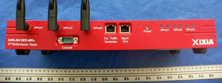
RCXGC617644
Aug 09, 2007802.11a/b/g Multi AP Emulator (Client Device)
Equipment Class
DTS - Digital Transmission System
RCX-EE11ABG3
May 09, 2004802.11 a/b/g Emulation Engine
Equipment Class
NII - Unlicensed National Information Infrastructure TX
RCX-EE11ABG
Aug 28, 2003802.11 a/b/g Emulation Engine
Equipment Class
NII - Unlicensed National Information Infrastructure TX