RF7SI654RX433MHz Radio Transmitter
STL International Ltd.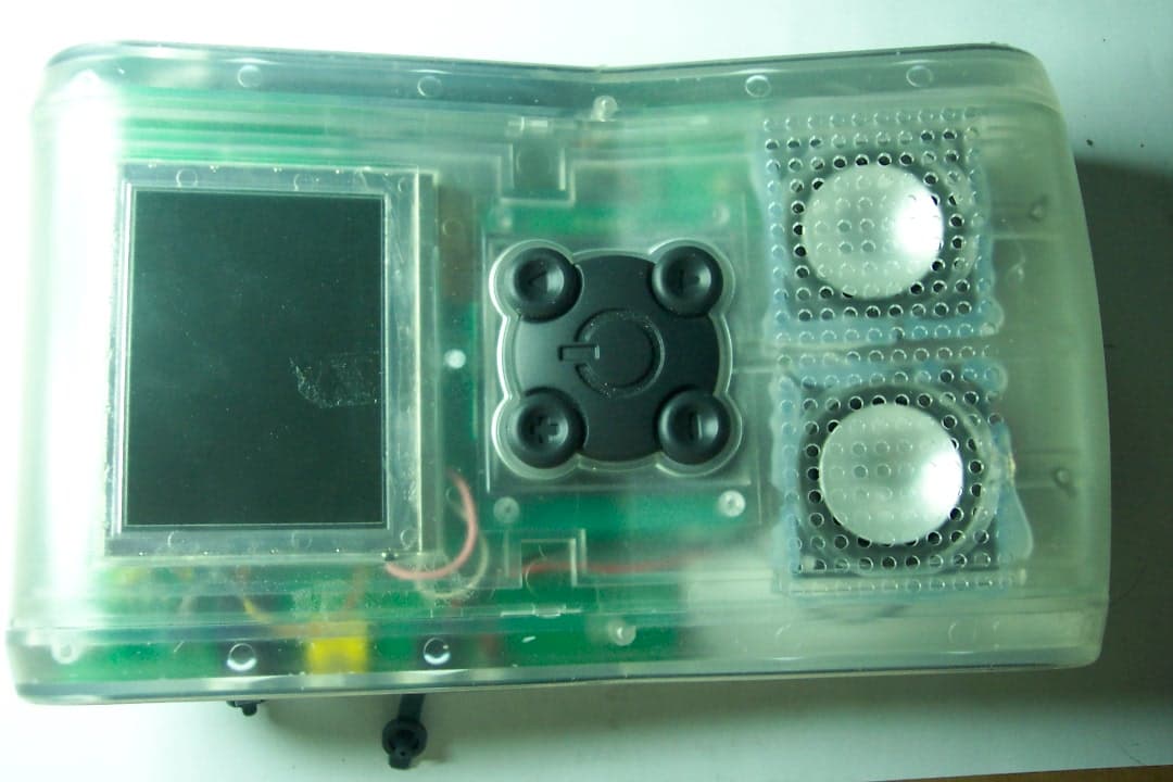
Click to zoom
Application Details
- Equipment Class
- DSC - Part 15 Security/Remote Control Transmitter
- Date of Grant
- Nov 03, 2003
- Application Purpose
- Original Equipment
- Date of Application
- Nov 03, 2003
- Equipment Note
- 433MHz Radio Transmitter
- Frequency Range
- 433.86900000 - 433.86900000
- Company
- STL International Ltd.
- Country
- China
Documents & Files
Document Text
Text extracted from the exhibit documents filed with the FCC. Open a document above to read the original.
Users Manual
User Manual for SI654 TVAnywhere Controls and Indicators – Base Station A. Video/Audio Input 1. RF in 2. Video In 3. Audio R in 4. Audio L in 5. Remote control IR receiver B. Output connector 1. Remote Control IR Transmitter C. Control buttons 1. Power On/Off Switch 2. Learn button D. Indicators 1. Power On LED – red a. Turn on by hardware to indicate Power is ON 2. Operating LED – Green a. OFF – Standby mode b. Always On – Normal TV mode c. Flashing – IR learning mode E. RF modules 1. Video channel : 2.4G Transmitter with three channels 2. Remote Control channel : 433.9Mhz receiver Controls and Indicators - Remote Monitor A. Input 1. Video channel from 2.4G 2. Battery charger contacts B. Output 1. LCD screen 2. Stereo Speakers 3. Video/Audio Out 4 position phone Jack 4. Stereo Headset jack 5. Subwoofer jack 6. Power/Charge LED C. Control buttons 1. POWER 2. CH- 3. CH- 4. VOL + 5. VOL - 6. MODE + 7. MODE - 8. MODE D. RF modules 1. Video channel : 2.4G Receiver with three channels 2. Remote Control channel : 433.9Mhz Transmitter Accessories 1. Stereo earbud type headset 2. RF splitter 3. Video splitter 4. RF 75 ohm coaxial cable – 2 meter 5. Composite video cable – 2 meter 6. Stereo audio cable – 2 meter 7. Video+audio out cable with four position phone plug 8. AC adapter 1. Power ON a. Press the power switch on the Base and the red LED should turn ON b. Press the POWER button on the remote. The green LED on the Base should lit and video should be displayed. 3. Power Off a. Press the POWER button on the Remote while power is on will turn off the power of the Remote and put the Base in standby mode. b. The green LED on th eBase should be off and the red LED should remain ON. c. To switch off power to the Base, press the power switch. The red LED will be Off 4. CH+/CH-: to adjust the TV channel a. Press the CH+ /CH- button to step one up or down one channel b. Display Channel number on upper right corner of screen c. If button is not released within 2 seconds->jump 5 channels for every 0.5 second d. When button is released-> return to normal e. This two buttons only function in TV mode. 5. VOL+/VOL-: to adjust the audio level a. Press VOL+/VOL- button to change audio volume b. Volume level is from 0 to 7 c. Level 0 will mute the speaker completely 6. M+/M-: to adjust brightness of screen a. Press M+/M- to adjust brightness b. Brightness level is in the range from 1 to 16 7. Reset 2.4G channel to default: to set 2.4G channel to CH1 2.4G RF channel is lost Press and hold MODE button for 2 seconds or until Video is received on screen 8. IR Remote control learning Base Station Indications Remote Screen display a. Press “Learn” key and hold for 2 seconds to start learning UP key. Display “Learn Remote Control Keys “ on top of screen b Green LED flashing at 4 Hz Display and flash on line above bottom line “Press and hold Channel Up key of remote control” c Receive IR code from receiver and stored in EEPROM Display on fourth line “Learning Channel Up key” d If no IR code received within 10 seconds, return to normal, otherwise Display on fourth line “No valid key learned” e Green LED flashing at 1 Hz Display on fourth line “Channel Up Key Learned” Display and flash on bottom line “Press Learn button” f Press “Learn” button to start learning Down key Green LED flashing again at 4 Hz Display and flash on one line above bottom “Press and hold Channel Down key of remote control” g Receive IR code from receiver and stored in EEPROM Display on fourth line “Learning Channel Down key” h Green LED flashing at 1 Hz Display on fifth line “Channel Down Key Learned” If no IR code received within 10 seconds, return to normal, otherwise Display on fifth line “No valid key learned i Return to normal mode after 10 seconds or Learn button is pressed Display and flash on bottom line “Press Learn button or Wait ” Mode Button Functions Common Operation a. Press MODE button to active MODE functions b. Press MODE button again to return to normal video viewing c. Press M+/M- buttons to select functions d. Press CH+/CH-, VOL+/VOL- to input parameters Operation of individual functions 1. TV/Video : to select video input from either TV tuner or Video In a. Press MODE button once to activate b. Current input source: “TV” or “VIDEO” will be displayed on top right corner of screen c. Press M+ button to go to Set 2.4G channel d. Press M- button to go to Fine tune e. Press VOL+ button to select TV input f. Press VOL – button to select Video input g. Press MODE again or timeout after 10 seconds turns off OSD and return to normal. 2. Set 2.4G channel : to change the channel of 2.4G transmitter to avoid interference a. Current 2.4G channel displayed on top right corner a. Press M+ button to go to Auto_Program b. Press M-button to go to TV/Video c. Press VOL+/VOL- to change 2.4G channel d. Press MODE button or timeout after 10 seconds, disable OSD and return to normal 3. Auto_Program: to scan all available TV channels from RF tuner and store setting in EEPROM a. Display “Auto Programming” b. Press M+ button to go to Program_Memory c. Press M-button to go to Set2.4G d. Press V+ to select TV/CATV e. Press CH+ button to start programming f. After Auto Programming finished, first scanned channel is displayed 4. Program_Memory: to add or delete a channel in program memory a. Display “Program Memory” b. Press M+ button -> Fine_Tune c. Press M- button -> Auto_Program d. Press MODE button or timeout after 10 seconds, disable OSD and return to normal mode, otherwise, e. Press VOL+ to select Add Channel, f. Press VOL- to select delete Channel, To add a channel g. Display on second line “Add Channel nnn”, nnn=current channel number h. Display on bottom line “Press VOL+ button to confirm” i. Press CH+ or CH- buttons to change channel to add j. Press and hold CH+ or CH- buttons for 1 seconds to skip 10 channels in either direction k. Display new channel number.. l. Press VOL+, button again to confirm the ADD function m. Display on second line “Ch…
Text truncated - open the document above for the full version.
Operational Description
STL SI654 Operation Description A. Base Unit 1. The whole base unit is controlled by the MCU U1. 2. The EEPROM U2 keeps some important data while the unit is powered off. 3. When the LEARN button is pressed, the MCU U1 flashes the LEARN LED to indicate the unit is in learn mode. The MCU detects the IR (Infrared) signal that is generated by other remote control device with the IR RECEIVER and saves the data into EEPORM U2. 4. The MCU outputs the same learned signal to the IR LED V3 when is needed. 5. The MCU U1 receives the commend signal from the Remote Unit by RF receiver IC102 and T8. 6. The MCU U1 generates a signal to the 2.4 Ghz module to select which channel is used. 7. The MCU U1 also selects the input source (from AV input or TV) by the AV selector U3. 8. If the TV is selected, then the MCU will contorl the TV tuner to work under the select TV channel. 9. The MCU U1 also controlls the OSD (On Screen Display) circuit to display some characters on the screen when it is needed. 10. The MCU can detect whether there is a video signal or not from the synchronous separation circuit T7. 11. The MCU will mute the audio signal (by T9,T10) while changing the TV channel to prevent the noise is heard. 12. The whole Base unit is powered by an AC adaptor and the Power Supply circuit. B. Remote Unit 1. The whole Remote unit is controlled by the MCU U101. 2. The EEPROM U104 keeps some important data while the unit is powered off. 3. The reset circuit T101 provides a power on reset to the MCU. 4. When any key is pressed, the MCU will send the command to the Base unit by the RF transmitter T4. 5. The MCU U101 generates a signal to the 2.4 Ghz module to select which channel is used. 6. The MCU U101 controlls the LCD brightness by the Brightness Control R141-R144. 7. The MCU U101 controlls the Volume by the Volume Control circuit T104-T110. 8. The whole Remote unit is powered by a 12V battery. This battery can be charged by a DC Adapter and the charge circuit T210- T214. 9. The Audio power supply is controlled by T207,T208. The LCD power supply is controlled by T203 - T206. The 5V power supply for the MCU and 2.4 Ghz module is submitted by U202, T201,T202. 10. The MCU monitors the voltage of the battery by the Battery Low detector. If the battery is low, then the MCU will transmit an audio beep to the amplifiers to alert the user. If the battery is too low, then the MCU will cut off the power to protect the battery. C. Charger 1. The Charger is used to charge the battery while the battery is removed from the Remote Unit. 2. The charge condition indictor LED (LED301) on the Charger is used to indicator the charge condition : Red - Charger has power Flashing Green - Charging Green - Fully charged 3. When the battery is not fully charged, the charge current will be higher. The current is flow through T302,R306,D302. 4. When the battery is fully charged, the voltage detector will be triggered and turned off T302. Then a small current will be maintained through R301 and D301. 5. For some reason if the voltage detector is not triggered but the battery is charged for more than 12 hours, then the timer will turn off T302 and maintained a small charge current.
Test Report
Report No.: 03.10.1909EF-2 Page: 1 of 18 FCC ID: RF7SI654RX Authorized Signature: Kent Hsu Laboratory Manager SGS-CSTC Co.,Ltd. This report refers to the General Conditions for Inspection and Testing Services, printed overleaf This report details the results of the testing carried out on one sample. The results contained in this test report do not relate to other samples of the same product and does not permit the use of the SGS PRODUCT CERTIFICATION MARK.. The manufacturer should ensure that all products in series production are in conformity with the product sample detailed in this report. This report may only be reproduced and distributed in full. If the product in this report is used in any configuration other than that detailed in the report, the manufacturer must ensure the new system complies with all relevant standards. Any mention of SGS International Electrical Approvals or testing done by SGS International Electrical Approvals in connection with, distribution or use of the product described in this report must be approved by SGS International Electrical Approvals in writing. Member of the SGS Group (Société Générale de Surveillance) SGS-CSTC Standards Technical Services Ltd. 1/F., Building No. 1 Building, Agriculture Machinery Materials Co. Wushan Road, Shipai, Tianhe District,Guangzhou, China Telephone: +86 (0) 20 3848 1001 Fax: +86 (0) 20 3848 1006 [email protected] FEDERAL COMMUNICATIONS COMMISSION Registration number: 282399 FCC TEST REPORT Application No. : 03.10.1909EF-2 Applicant : STL INTERNATIONAL LTD FCC ID : RF7SI654RX Fundamental Frequency : 443.869Hz Equipment under Test (EUT): Name : TV Anywhere Model : SI654 Standards : FCC PART 15, SUBPART C : 2002 Date of Receipt : 10 October 2003 Date of Test : 12 to 15 October 2003 Date of Issue : 25 October 2003 Test Result : PASS * * In the configuration tested, the EUT complied with the standards specified above. FCC ID No.: RF7SI654RX Report No.: 03.10.1909EF-2 Page: 2 of 18 SGS-CSTC Standards Technical Services Ltd. 2 Contents Page 1 COVER PAGE.........................................................................................................................................................1 2 CONTENTS .............................................................................................................................................................. 2 3 GENERAL INFORMATION.................................................................................................................................. 3 3.1 CLIENT INFORMATION....................................................................................................................................... 3 3.2 DETAILS OF E.U.T. ............................................................................................................................................ 3 3.3 DESCRIPTION OF SUPPORT UNITS....................................................................................................................... 3 3.4 TEST LOCATION................................................................................................................................................. 3 3.5 OTHER INFORMATION REQUESTED BY THE CUSTOMER...................................................................................... 3 3.6 TEST FACILITY................................................................................................................................................... 4 4 TEST RESULTS....................................................................................................................................................... 5 4.1 TEST INSTRUMENTS........................................................................................................................................... 5 4.2 E.U.T. OPERATION............................................................................................................................................ 5 4.3 TEST PROCEDURE & MEASUREMENT DATA....................................................................................................... 6 4.3.1 Radiated Emissions ...................................................................................................................................... 6 4.3.2 Conducted Emissions Mains Terminals, 150kHz to 30MHz ........................................................................ 9 4.3.3 Measurement Data ....................................................................................................................................... 9 4.3.4 Occupied Bandwidth .................................................................................................................................. 10 5 PHOTOGRAPHS - RADIATED EMISSION TEST SETUP............................................................................. 13 6 PHOTOGRAPHS – CONUCTED EMISSION TEST SETUP .......................................................................... 14 7 PHOTOGRAPHS - EUT CONSTRUCTIONAL DETAILS .........................................................................15-18 FCC ID No.: RF7SI654RX Report No.: 03.10.1909EF-2 Page: 3 of 18 SGS-CSTC Standards Technical Services Ltd. 3 General Information 3.1 Client Information Applicant: STL INTERNATIONAL LTD Address of Applicant: TUNG KONG INDUSTRIAL ZONE.LIU MEI VILLAGE,YUEN ZHOU,BOLOU,PRC 3.2 Details of E.U.T. Product Name: TV Anywhere Model: SI654 Power Supply: 120Vac / 60Hz (for AC/DC Adapter supplied) AC/DC Adapter: Input: 120Vac/60Hz; Output: 1.5Vdc, 700mA. Power Cord: 2.0 m , 2 wires unshielding DC cable 3.3 Description of Support Units The EUT was tested as an independent unit: a 433MHz radio transmitter and as a receiver for the 2.4G TV transmitter which ID No. is RF7SI654TX in report 03.10.1909EF-1. Only press the function buttons to select the channel, adjust volume or brightness i.e., the transmitter is on once. Other time, the product is in receiving status. 3.4 Test Location All tests were performed …
Text truncated - open the document above for the full version.
Test Setup Photos
Photographs - Radiated Emission Test Setup Photographs – Conducted Emission Test Setup
Contact Information
Applicant
Esa Chiau(Assistant Marketing Manager)
Test Firm
SGS-CSTC Standards Technical Services Co., LtdJerry Chan
Technical Specifications
| # | Rule Parts | Frequency Range | Power Output |
|---|---|---|---|
| 1 | 15.231 | 433.869 MHz - 433.869 MHz | - |
Other Applications from STL International Ltd.

RF7-RX5-TX2
Jul 07, 2013Remote Controller
Equipment Class
DSC - Part 15 Security/Remote Control Transmitter
RF7POM0001
Nov 30, 20102.4GHz Transceiver Module
Equipment Class
DXX - Part 15 Low Power Communication Device Transmitter
RF7SI398
Dec 21, 2004Dog Training Device
Equipment Class
DSC - Part 15 Security/Remote Control Transmitter
RF7SI670TX
Oct 24, 20042.4GHz TV Transmitter
Equipment Class
DXT - Part 15 Low Power Transceiver, Rx Verified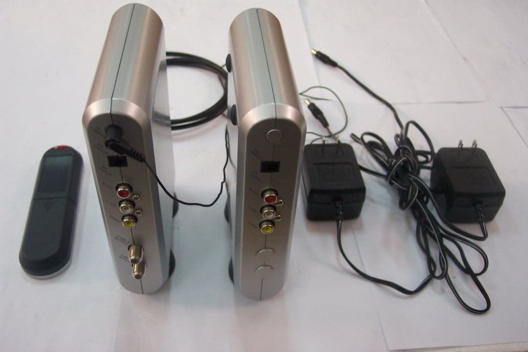
RF7SI670RX
Oct 24, 2004Remote Control
Equipment Class
DSR - Part 15 Remote Control/Security Device Transceiver