RF7SI676433MHz Radio Transmitter
STL International Ltd.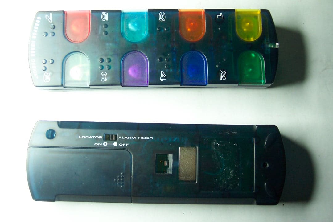
Click to zoom
Application Details
- Equipment Class
- DSC - Part 15 Security/Remote Control Transmitter
- Date of Grant
- Dec 11, 2003
- Application Purpose
- Original Equipment
- Date of Application
- Dec 11, 2003
- Equipment Note
- 433MHz Radio Transmitter
- Frequency Range
- 433.92000000 - 433.92000000
- Company
- STL International Ltd.
- Country
- China
Documents & Files
Document Text
Text extracted from the exhibit documents filed with the FCC. Open a document above to read the original.
Users Manual
“Now You Can Find It!” ® SI676 Instructions Read and save these instructions. Image to come Dear Sharper Image Customer, Thank you for your purchase of a Sharper Image product. We appreciate your business very much. This item was created by Sharper Image Design, our company’s own product development group. Please accept my personal assurance of your complete satisfaction with this product’s quality and performance. We offer generous return privileges and excellent warranties on all our products. For more than 25years, The Sharper Image has shared the fun of discovering innovative products that make life better and more enjoy- able. We’ve been in business a long time because we are an exciting place to shop and — just as importantly — we strive to deliver great customer service that exceeds your expectations. Enjoy your purchase! Respectfully, Richard Thalheimer Founder, Chairman and Chief Executive Officer Call 1-800-344-4444for 24-7ordering and customer service, or go to , our complete online store. Introduction ................................................................................. Batteries ...................................................................................... Mounting Bracket and Locator Discs ........................................... Operation ................................................................................... Statement of FCC/DHHS Compliance ......................................... One Year Warranty ...................................................................... Table of Contents “Now You Can Find It!” ® consists of a Base, a mounting bracket and eight individual Locators. Attach a Locator to an object and the next time you need to find the object, press the matching button on the Base. The Base sig- nals the Locator to beep and the beeps lead you to the Locator (and the object). For both products, replace the batteries if they are weak or if the product does not appear to function properly. Introduction Image to come The “Now You Can Find It!” ® Base runs on two AA alkaline bat- teries. Each of the color-coded Locators run on CR2032 button lithium coin-cell batteries. The first set of batteries for the locators have been factory- installed. Battery life varies according to frequency of use, but batteries for the Locators should be changed at least once a year. For both products, replace the batteries if they are weak or if the product does not function properly. Base Battery Compartment Requires two AA alkaline batteries Locator Battery Compartment Runs on one CR2032 battery. To slide compartment from the locator, remove screw on back. Batteries Image to come The mounting bracket can be attached to any convenient loca- tion using double-sided adhesive, the magnetic strip or by plac- ing a screw in the wall and sliding the keyhole on the back over the screw. When the Base is slid onto the bracket, the base automatically turns off. To personalize the button names, lift off the clear protector, Wrote a name on the card or apply one of the icon stickers next to the button. Attach the Locator using its keyring or double-sided adhesive pad. Mounting Bracket and Locator Discs Image to come 1. The Base must be detached from the bracket. 2. Press the button on the Base that matches the color of the Locator you are trying to find. 3. The Base sends out several “Search” signals. If the signal reaches the Locator, it will signal back with a series of “beeps.” It may be necessary to move around the area and press the button several times before you are able to locate the object. The Locator and Base will communicate within a 30 foot range. To prevent losing the Base, always return it to the bracket when not in use. If it has been left out of the bracket, the BASE “beeps” after two minutes. It will beep again every six minutes until it is returned to the bracket. To turn off, slide the switch located on the back of the Base to the off posi- tion. Button color of Base should match Locator color. Operation Image to come WARNING:Changes or modifications to this unit not expressly approved by the party responsible for compliance could void the user’s authority to operate the equipment. NOTE:This product complies with DHHS Rule 21 subchapter J at date of manufacture. This equipment has been tested and found to comply with the limits for a Class B digital device, pursuant to Part 15 of the FCC Rules. These limits are designed to provide reasonable protection against harmful interference in a residential installation. This equipment generates, uses, and can radiate radio frequency energy and, if not installed and used in accordance with the instructions, may cause harmful interference to radio communi- cations. However, there is no guarantee that interference will not occur in a particular installation. If this equipment does cause harmful interference to radio or tel- evision reception, which can be determined by turning the equipment off and on, the user is encouraged to try to correct the interference by one or more of the following measures: •Reorient or relocate the receiving antenna. •Increase the separation between the equipment and receiver. Statement of FCC/DHHS Compliance •Connect the equipment into an outlet on a circuit different from that to which the receiver is connected. •Consult the dealer or an experienced radio/TV technician for assistance. Statement of FCC/DHHS Compliance What Is Covered This warranty covers any defects in materials or workmanship, with the exceptions stated below. How Long Coverage Lasts This warranty runs for one year from the date of original purchase. What Is Not Covered This warranty does not cover damage caused by misuse or use other than as intended and described in the product instruction manual, or loss or damage to batteries or removable parts. What The Sharper Image Will Do The Sharper Image will repair any defects in materials or workmanship. In the event repair is not possible, The Sharper Image will …
Text truncated - open the document above for the full version.
Block Diagram
55 44 33 22 11 D D C C B B A A Antenna (Q2) SignalOut Analog Signal In RF Receiving SignalConvertion (U1) Buzzer Unit U3 WakeUp signal WakeUp trigger Controller Unit (U2) Data Out Data In 4 Seconds ClockTimer Power Control SoundO/P BLK0478 0 SI676/IU676 - Function Block Diagram for Locator A 12 Wednesday, November 19, 2003 TitleSize Document Number Rev Date: Sheet of Power In Power In D2 LED R4 55 44 33 22 11 D D C C B B A A RF Modulation & Transmittion RF Out Power In Buzzer Unit Data Out Buttons Input ControllerUnit (U1) Power Control Timer Reset Data In 60 secondsClockTimer Timer WakeUp Q4 Q3 Wall On TimerSwitch (SW1) Wall OnTimer Input KeyBoardInput SoundO/P BLK0478 0 SI676 / IU676 - Function Block Diagram for the Transmitter Unit A 11 Wednesday, November 19, 2003 TitleSize Document Number Rev Date: Sheet of SAW1433.9Mhz 1 23 4 Power Indicator LED1
Operational Description
Confidential Principle of Operation of SI676/IU676 Transmitter Cradle Sw LED indicator buzzer Key matrix Standby Mode Under standby condition the controller is in sleep mode and power to the transmitter is switched off. The 60 seconds wake up clock is running all the time and will generate an interrupt signal to the main controller every 60 seconds. Transmit Mode When the user press any button, the main controller will wake up turn on the power for the transmitter. Then it sends an ID code corresponding to the position of the key pressed. The transmission is repeated for 4.5 seconds and then the main controller switch off the power to the transmitter. The LED is turned on to indicate that RF transmission is active. The controller will enter standby mode after transmission is completed to save power. Off Cradle Alert If the transmitter is off the mounting cradle, an interrupt will wake up the controller to start a timer. After the first two minutes and every six minutes afterwards, the controller will generate an audio signal to alert the user that the transmitter is not sitting on the cradle. Main Controller 433Mhz transmitter 60 s Wake up clock Receiver LED buzzer Standby Mode The main controller will be in sleep mode and the receiver power is turned off during standby mode. Every 4 seconds the clock circuit will generate an interrupt signal to wake up the controller. The controller will then turn on the RF receiver and wait of an valid data codes from the transmitter. If there is no valid code detected within 30ms, it will then turn off the receiver and enter sleep mode again. Receiving Mode When the controller recognizes a valid data code from the transmitter, it will generate a two tone audio signal and flash the LED as well to indicate that a valid code is received. The audio and visual signals will last for 3-5 seconds before the controller enter standby mode again. Main Controller 433Mhz receiver 4 s Wake up clock
Test Report
Report No.: 03.11.2126EF-1 Page: 1 of 13 FCC ID: RF7SI676 Authorized Signature: Kent Hsu Laboratory Manager SGS-CSTC Co.,Ltd. This report refers to the General Conditions for Inspection and Testing Services, printed overleaf This report details the results of the testing carried out on one sample. The results contained in this test report do not relate to other samples of the same product and does not permit the use of the SGS PRODUCT CERTIFICATION MARK.. The manufacturer should ensure that all products in series production are in conformity with the product sample detailed in this report. This report may only be reproduced and distributed in full. If the product in this report is used in any configuration other than that detailed in the report, the manufacturer must ensure the new system complies with all relevant standards. Any mention of SGS International Electrical Approvals or testing done by SGS International Electrical Approvals in connection with, distribution or use of the product described in this report must be approved by SGS International Electrical Approvals in writing. Member of the SGS Group (Société Générale de Surveillance) SGS-CSTC Standards Technical Services Ltd. 1/F., Building No. 1 Building, Agriculture Machinery Materials Co. Wushan Road, Shipai, Tianhe District,Guangzhou, China Telephone: +86 (0) 20 3848 1001 Fax: +86 (0) 20 3848 1006 [email protected] FEDERAL COMMUNICATIONS COMMISSION Registration number: 282399 FCC TEST REPORT Application No. : 03.11.2126E Applicant : STL INTERNATIONAL LTD FCC ID : RF7SI676 Fundamental Frequency : 433.920Hz Equipment under Test (EUT): Name : TV Anywhere Model : SI676 Standards : FCC PART 15, SUBPART C : 2002 Date of Receipt : 21 November 2003 Date of Test : 25 November to 05 December 2003 Date of Issue : 10 December 2003 Test Result : PASS * * In the configuration tested, the EUT complied with the standards specified above. FCC ID No.: RF7SI676 Report No.: 03.11.2126EF-1 Page: 2 of 13 SGS-CSTC Standards Technical Services Ltd. 2 Contents Page 1 COVER PAGE.........................................................................................................................................................1 2 CONTENTS .............................................................................................................................................................. 2 3 GENERAL INFORMATION.................................................................................................................................. 3 3.1 CLIENT INFORMATION....................................................................................................................................... 3 3.2 DETAILS OF E.U.T. ............................................................................................................................................ 3 3.3 DESCRIPTION OF SUPPORT UNITS....................................................................................................................... 3 3.4 TEST LOCATION................................................................................................................................................. 3 3.5 OTHER INFORMATION REQUESTED BY THE CUSTOMER...................................................................................... 3 3.6 TEST FACILITY................................................................................................................................................... 4 4 TEST RESULTS....................................................................................................................................................... 5 4.1 TEST INSTRUMENTS........................................................................................................................................... 5 4.2 E.U.T. OPERATION............................................................................................................................................ 5 4.3 TEST PROCEDURE & MEASUREMENT DATA....................................................................................................... 6 4.3.1 Radiated Emissions ...................................................................................................................................... 6 4.3.2 Occupied Bandwidth .................................................................................................................................... 8 5 PHOTOGRAPHS - RADIATED EMISSION TEST SETUP............................................................................. 11 6 PHOTOGRAPHS - EUT CONSTRUCTIONAL DETAILS .........................................................................12-13 FCC ID No.: RF7SI676 Report No.: 03.11.2126EF-1 Page: 3 of 13 SGS-CSTC Standards Technical Services Ltd. 3 General Information 3.1 Client Information Applicant: STL INTERNATIONAL LTD Address of Applicant: TUNG KONG INDUSTRIAL ZONE.LIU MEI VILLAGE,YUEN ZHOU,BOLOU,PRC 3.2 Details of E.U.T. Product Name: Wireless Electronic Locator Model: SI676 Power Supply: 3.0Vdc ( 2 x ‘AAA’ Size Batteries) 3.3 Description of Support Units The EUT was tested as an independent unit: a 433.920MHz radio transmitter. 3.4 Test Location All tests were performed at:- SGS-CSTC Standards Technical Services Ltd., Guangzhou Safety & EMC Laboratory, 1/F, Building No. 1, Agriculture Machinery Materials Company Warehouse Ltd., Wushan Road Shipai, Tianhe District, Guangzhou, China. P.C. 510630. Tel: +86 20 3848 1001 Fax: +86 20 3848 1006 3.5 Other Information Requested by the Customer None. FCC ID No.: RF7SI676 Report No.: 03.11.2126EF-1 Page: 4 of 13 SGS-CSTC Standards Technical Services Ltd. 3.6 Test Facility The test facility is recognized, certified, or accredited by the following organizations: • NVLAP – Lab Code: 200611-0 SGS-CSTC Standards Technical Services Co., Ltd., Guangzhou EMC Laboratory is recognized under the National Voluntary Laboratory Accreditation Program (NVLAP/NIST). NVLAP Code: 2000611-0. Effective through …
Text truncated - open the document above for the full version.
Contact Information
Applicant
Esa Chiau(Assistant Marketing Manager)
Test Firm
SGS-CSTC Standards Technical Services Co., LtdJerry Chan
Technical Specifications
| # | Rule Parts | Frequency Range | Power Output |
|---|---|---|---|
| 1 | 15.231 | 433.92 MHz - 433.92 MHz | - |
Other Applications from STL International Ltd.

RF7-RX5-TX2
Jul 07, 2013Remote Controller
Equipment Class
DSC - Part 15 Security/Remote Control Transmitter
RF7POM0001
Nov 30, 20102.4GHz Transceiver Module
Equipment Class
DXX - Part 15 Low Power Communication Device Transmitter
RF7SI398
Dec 21, 2004Dog Training Device
Equipment Class
DSC - Part 15 Security/Remote Control Transmitter
RF7SI670TX
Oct 24, 20042.4GHz TV Transmitter
Equipment Class
DXT - Part 15 Low Power Transceiver, Rx Verified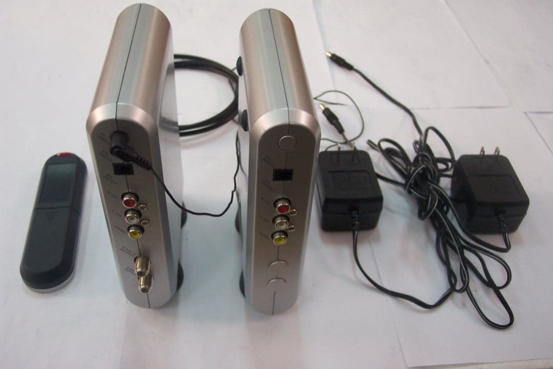
RF7SI670RX
Oct 24, 2004Remote Control
Equipment Class
DSR - Part 15 Remote Control/Security Device Transceiver