RF7WP-2Wireless Pendant
STL International Ltd.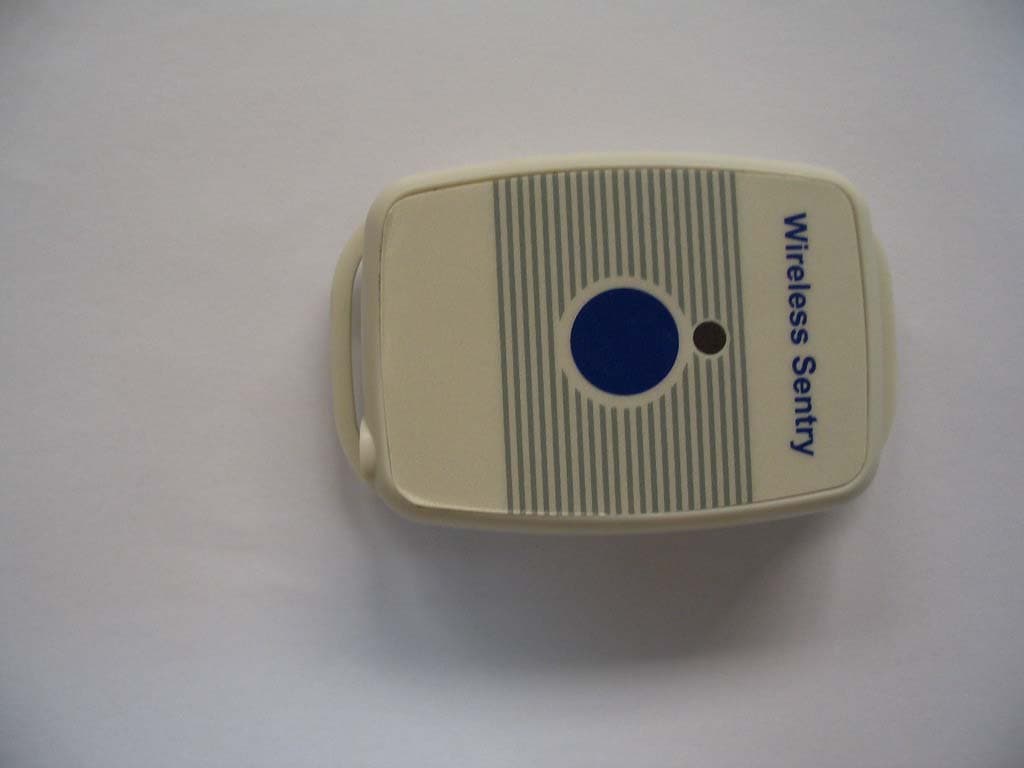
Click to zoom
Application Details
- Equipment Class
- DXX - Part 15 Low Power Communication Device Transmitter
- Date of Grant
- Jun 28, 2004
- Application Purpose
- Original Equipment
- Date of Application
- Jun 28, 2004
- Equipment Note
- Wireless Pendant
- Frequency Range
- 915.00000000 - 915.00000000
- Company
- STL International Ltd.
- Country
- China
Documents & Files
Document Text
Text extracted from the exhibit documents filed with the FCC. Open a document above to read the original.
Users Manual
Wireless Pendant ™ WP-2 Operating Instructions NOTE: The Pendant is water-resistant, that is, it can withstand limited exposure to liquids. However, it is not waterproof, and should not be immersed in any liquid. Universal Medical Products’ Wireless Pendant™ can be used in place of or along with a Transmitter (model WT-2) in the UMP Wireless Sentry™ monitoring system to send an emergency alarm signal to the Receiver (model WR-3 or WR-4). It can be worn either around the neck or on the wrist. It operates on three LR44 1.5V button cell batteries (included). On Standby status, these batteries will last for approximately 3 years. We recommend that you test the Pendant periodically to be sure the batteries are working. If the communication distance or the brightness of the alarm LED is reduced, replace all three batteries with new ones. To replace batteries 1.Remove the two screws on the back of the Pendant and lift off the front of the casing. 2.Pry out the old batteries with a pen or small screwdriver. 3.Place the new batteries into position, being sure to align the polarities correctly. Match the “+” sign on the batteries with the “+” marked in the battery compartment. 4.Before screwing the front of the unit back into place, press the blue circle to be sure the batteries have been installed correctly and are operational. The LED should go on. 5.Reprogram the device if necessary (see below). Programming The Pendant can activate the Receiver after being programmed as described below: 1.Press and hold the PROGRAM button of the Receiver until the green PROGRAM LED lights up. The LED indicating the first empty station location will flash. 2.Press the PROGRAM button to select the desired empty location. The LED of each empty station will light up in turn each time the button is pushed. 1 3.Press and hold the ALARM button (blue circle) on the Pendant until you hear a long beep from the Receiver and the station LED stops flashing. 4.Press the PROGRAM button to program the next empty station, OR Press CONFIRM on the Receiver to return to normal monitor mode. Operation In an emergency, the Receiver can be activated using the Pendant. Pressing the ALARM button once will transmit the alarm signal to the Receiver for approximately 3 minutes. The alarm sound on the Receiver will be activated. The LED on the Pendant will flash to help the caregiver identify the source of the alarm signal. To stop the alarm sound on the Receiver, press the ALARM RESET button on the Receiver. The corresponding location LED will also go off. The Pendant will be disabled for about 6 seconds after sending the alarm signal. After this time, the Pendant will reset itself automatically and can then be used again. For more details on the operation of the Wireless Sentry system, see the Operator’s Manual included with the Receiver. 2 FCC Warning Changes or modifications to this unit not expressly approved by the party responsible for compliance could void the user’s authority to operate the equipment. Radio Frequency Interference This equipment has been tested and found to comply with the limits for a Class B digital device, pursuant to Part 15 of the FCC Rules. These limits are designed to provide reasonable protection against harmful interference in a residential installation. This equipment generates, uses and can radiate radio frequency energy and, if not installed and used in accordance with the instructions, may cause harmful interference to radio communications. However, there is no guarantee that interference will not occur in a particular installation. If this equipment does cause harmful interference to radio or television reception which can be determined by turning the equipment off and on, the user is encouraged to try to correct the interference by one or more of the following measures. •Increase the separation between the equipment and receiver. •Connect the equipment into an outlet on a circuit different from that on which the receiver is needed. Consult the dealer or an experienced radio/TV technician for help. 3 Limited Warranty UNIVERSAL MEDICAL PRODUCTS, INC., guarantees the quality and workmanship of the Wireless Sentry™ Receiver and each Transmitter (including Pendant) and Charger for a period of one (1) year from date of purchase. This warranty is in force provided there is no evidence of misuse or improper installation. Under the conditions of this warranty, UNIVERSAL MEDICAL PRODUCTS, INC., agrees to repair and return any defective or inoperative Wireless Sentry™ units, components, or parts within 30 days without charge. Units, components or parts that are determined not to be covered by this warranty because of time, abuse/misuse, or improper installation, will be repaired or replaced on an established cost repair basis within 30 days. UNIVERSAL MEDICAL PRODUCTS, INC., DOES NOT CLAIM THAT THE WIRELESS SENTRY™ SYSTEM WILL PREVENT BED- AND CHAIR-RELATED FALLS WITHOUT FAIL. IT DOES CLAIM THAT, WITH A COORDINATED EFFORT FROM THE INSTITUTION NURSING STAFF AND AN ACCEPTABLE FALLS PREVENTION PROGRAM, THE WIRELESS SENTRY™ SYSTEM CAN HELP TO REDUCE THE NUMBER OF FALLS THAT OCCUR WITHIN AN INSTITUTION. All questions or inquiries should be directed to: UNIVERSAL MEDICAL PRODUCTS, INC. 1620 N. 20 th Circle Lincoln, NE 68503-1103 Tel.: (888) 716-0077 (Toll Free) or (718) 499-0020 Fax: (732) 583-6923 or (718) 499-6494 4 Printed in China
External Photos
FCC ID No.: RF7WP-2 Report No.: 04.05.0993EF Page: 10 of 11 SGS-CSTC Standards Technical Services Ltd. 6 Photographs - EUT Constructional Details
ID Label/Location Info
Applicant: STL INTERNATIONAL LTD FCC ID: RF7WP-2 Proposed Label Location on EUT EUT Rear View/Proposed FCC Mark Location FCC ID: RF7WP-2
Internal Photos
FCC ID No.: RF7WP-2 Report No.: 04.05.0993EF Page: 11 of 11 SGS-CSTC Standards Technical Services Ltd.
Operational Description
FCC ID: RF7WP-2 WP-2 Wireless Pendant Transmitter Principle of operation The WP-2 Wireless Pendant Transmitter will transmit an alarm signal with an ID to either WR-3 or WR-4 Alarm Receiver to give alert that someone is requesting assistance.. The RF transmitter is a Chip Con CC1050 RF transmit only chip. The chip is programmed to work at 915Mhz ISM band and data rate is approximately 1K baud. DATA is encoded in Manchester format. The logic functions are controlled by a EMP78C138 micro controller unit (MCU) which communicates with the RF chip via IIC bus. The MCU is normally in Sleep mode for power saving purpose. When the button is pressed, a signal will generate an interrupt to wake up the MCU. The MCU will then send out an alarm signal with an unique ID code to the Alarm Receiver. To ensure that the alarm is received, the same signal will be sent five times.
Test Report
Report No.: 04.05.0993EF Page: 1 of 11 FCC ID: RF7WP-2 Authorized Signature: Kent Hsu Laboratory Manager This report refers to the General Conditions for Inspection and Testing Services, printed overleaf This report details the results of the testing carried out on one sample. The results contained in this test report do not relate to other samples of the same product and does not permit the use of the SGS PRODUCT CERTIFICATION MARK.. The manufacturer should ensure that all products in series production are in conformity with the product sample detailed in this report. This report may only be reproduced and distributed in full. If the product in this report is used in any configuration other than that detailed in the report, the manufacturer must ensure the new system complies with all relevant standards. Any mention of SGS International Electrical Approvals or testing done by SGS International Electrical Approvals in connection with, distribution or use of the product described in this report must be approved by SGS International Electrical Approvals in writing. The report must not be used by the client to claim product certification, approval, or endorsement by NVLAP, NIST, or any agency of the federal government. All test results in this report can be traceable to National or International Standards. Member of the SGS Group (Société Générale de Surveillance) SGS-CSTC Standards Technical Services Ltd. 1/F., Building No. 1 Building, Agriculture Machinery Materials Co. Wushan Road, Shipai, Tianhe District,Guangzhou, China Telephone: +86 (0) 20 3848 1001 Fax: +86 (0) 20 3848 1006 [email protected] FEDERAL COMMUNICATIONS COMMISSION Registration number: 282399 FCC TEST REPORT Application No. : 04.05.0993E Applicant : STL INTERNATIONAL LTD FCC ID : RF7WP-2 Fundamental Frequency : 915 MHz Equipment under Test (EUT): Name : WIRELESS PENDANT Model : WP-2 Standards : FCC PART 15, SUBPART C : 2003 (Section 15.249) Date of Receipt : 10 May 2004 Date of Test : 26 to 27 May 2004 Date of Issue : 03 June 2004 Test Result : PASS * * In the configuration tested, the EUT complied with the standards specified above. FCC ID No.: RF7WP-2 Report No.: 04.05.0993EF Page: 2 of 11 SGS-CSTC Standards Technical Services Ltd. 2 Contents Page 1 COVER PAGE.........................................................................................................................................................1 2 CONTENTS .............................................................................................................................................................. 2 3 GENERAL INFORMATION.................................................................................................................................. 3 3.1 CLIENT INFORMATION....................................................................................................................................... 3 3.2 DETAILS OF E.U.T. ............................................................................................................................................ 3 3.3 DESCRIPTION OF SUPPORT UNITS....................................................................................................................... 3 3.4 TEST LOCATION................................................................................................................................................. 3 3.5 OTHER INFORMATION REQUESTED BY THE CUSTOMER...................................................................................... 3 3.6 TEST FACILITY................................................................................................................................................... 4 4 TEST RESULTS....................................................................................................................................................... 5 4.1 TEST INSTRUMENTS........................................................................................................................................... 5 4.2 E.U.T. OPERATION............................................................................................................................................ 5 4.3 TEST PROCEDURE & MEASUREMENT DATA....................................................................................................... 6 4.3.1 Radiated Emissions ...................................................................................................................................... 6 4.3.2 Band Edges................................................................................................................................................... 8 5 PHOTOGRAPHS - RADIATED EMISSION TEST SETUP............................................................................... 9 6 PHOTOGRAPHS - EUT CONSTRUCTIONAL DETAILS .........................................................................10-11 FCC ID No.: RF7WP-2 Report No.: 04.05.0993EF Page: 3 of 11 SGS-CSTC Standards Technical Services Ltd. 3 General Information 3.1 Client Information Applicant: STL INTERNATIONAL LTD Address of Applicant: TUNG KONG INDUSTRIAL ZONE.LIU MEI VILLAGE,YUEN ZHOU,BOLOU,PRC 3.2 Details of E.U.T. Product Name: WIRELESS PENDANT Model: WP-2 Power Supply: 4.5V DC (3 x ‘GPA76’ Button Cells) Power Cord: N/A- 3.3 Description of Support Units The EUT was tested as an independent unit: a 915MHz radio transmitter. 3.4 Test Location All tests were performed at:- SGS-CSTC Standards Technical Services Ltd., Guangzhou Safety & EMC Laboratory, 1/F, Building No. 1, Agriculture Machinery Materials Company Warehouse Ltd., Wushan Road Shipai, Tianhe District, Guangzhou, China. P.C. 510630. Tel: +86 20 3848 1001 Fax: +86 20 3848 1006 3.5 Other Information Requested by the Customer None. FCC ID No.: RF7WP-2 Report No.: 04.05.0993EF Page: 4 of 11 SGS-CSTC Standards Technical Services Ltd. 3.6 Test Facility The test facility is recognized, certified, or accredited by the following organizations: • NVLAP – Lab Co…
Text truncated - open the document above for the full version.
Test Setup Photos
FCC ID No.: RF7WP-2 Report No.: 04.05.0993EF Page: 9 of 11 SGS-CSTC Standards Technical Services Ltd. 5 Photographs - Radiated Emission Test Setup
Contact Information
Applicant
Esa Chiau(Assistant Marketing Manager)
Test Firm
SGS-CSTC Standards Technical Services Co., LtdJerry Chan
Technical Specifications
| # | Rule Parts | Frequency Range | Power Output |
|---|---|---|---|
| 1 | 15C | 915 MHz - 915 MHz | - |
Other Applications from STL International Ltd.

RF7-RX5-TX2
Jul 07, 2013Remote Controller
Equipment Class
DSC - Part 15 Security/Remote Control Transmitter
RF7POM0001
Nov 30, 20102.4GHz Transceiver Module
Equipment Class
DXX - Part 15 Low Power Communication Device Transmitter
RF7SI398
Dec 21, 2004Dog Training Device
Equipment Class
DSC - Part 15 Security/Remote Control Transmitter
RF7SI670TX
Oct 24, 20042.4GHz TV Transmitter
Equipment Class
DXT - Part 15 Low Power Transceiver, Rx Verified
RF7SI670RX
Oct 24, 2004Remote Control
Equipment Class
DSR - Part 15 Remote Control/Security Device Transceiver