RF7WR-3Wireless Receiver
STL International Ltd.
Click to zoom
Application Details
- Equipment Class
- DXT - Part 15 Low Power Transceiver, Rx Verified
- Date of Grant
- Jun 29, 2004
- Application Purpose
- Original Equipment
- Date of Application
- Jun 29, 2004
- Equipment Note
- Wireless Receiver
- Frequency Range
- 915.00000000 - 915.00000000
- Company
- STL International Ltd.
- Country
- China
Documents & Files
Document Text
Text extracted from the exhibit documents filed with the FCC. Open a document above to read the original.
External Photos
FCC ID No.: RF7WR-3 Report No.: 04.05.0994EF Page: 12 of 14 SGS-CSTC Standards Technical Services Ltd. 7 Photographs - EUT Constructional Details
ID Label/Location Info
Applicant: STL INTERNATIONAL LTD FCC ID: RF7WR-3 Proposed Label Location on EUT EUT Rear View/Proposed FCC Mark Location FCC ID: RF7WR-3
Internal Photos
FCC ID No.: RF7WR-3 Report No.: 04.05.0994EF Page: 13 of 14 SGS-CSTC Standards Technical Services Ltd. FCC ID No.: RF7WR-3 Report No.: 04.05.0994EF Page: 14 of 14 SGS-CSTC Standards Technical Services Ltd.
Operational Description
FCC ID: RF7WR-3 WR-3 Wireless Alarm Receiver Principle of operation The WR-3 Alarm Receiver is a wireless receiver to monitor alarm signals generated by WT-2, WP-2 and WFM-1 alarm transmitters. It also provides both audio and visual indications to tell which transmitter in one of the sixteen programmed locations is sending the alarm. The RF circuit is embedded inside a ChipCon CC1000 RF transceiver chip. The chip is programmed to work at 915Mhz ISM band and data rate is approximately 1K baud. DATA is encoded in Manchester format. The logic functions are controlled by a Holtek HT46R23 micro controller unit (MCU) which communicates with the RF chip via IIC bus. Besides receiving emergency alarms, the WR-2 also sends out polling signals to individual transmitter to check that they are within the RF communication range. If an alarm transmitter does not response to polling signal for longer than 1 minute, the WR-3 will generate an audio tone to alert that the transmitter is probably out of the communication range. The LED location representing the ID of the Transmitter will flash to indicate which transmitter is loosing the signal
Test Report
Report No.: 04.05.0994EF Page: 1 of 14 FCC ID: RF7WR-3 Authorized Signature: Kent Hsu Laboratory Manager This report refers to the General Conditions for Inspection and Testing Services, printed overleaf This report details the results of the testing carried out on one sample. The results contained in this test report do not relate to other samples of the same product and does not permit the use of the SGS PRODUCT CERTIFICATION MARK.. The manufacturer should ensure that all products in series production are in conformity with the product sample detailed in this report. This report may only be reproduced and distributed in full. If the product in this report is used in any configuration other than that detailed in the report, the manufacturer must ensure the new system complies with all relevant standards. Any mention of SGS International Electrical Approvals or testing done by SGS International Electrical Approvals in connection with, distribution or use of the product described in this report must be approved by SGS International Electrical Approvals in writing. The report must not be used by the client to claim product certification, approval, or endorsement by NVLAP, NIST, or any agency of the federal government. All test results in this report can be traceable to National or International Standards. Member of the SGS Group (Société Générale de Surveillance) SGS-CSTC Standards Technical Services Ltd. 1/F., Building No. 1 Building, Agriculture Machinery Materials Co. Wushan Road, Shipai, Tianhe District,Guangzhou, China Telephone: +86 (0) 20 3848 1001 Fax: +86 (0) 20 3848 1006 [email protected] FEDERAL COMMUNICATIONS COMMISSION Registration number: 282399 FCC TEST REPORT Application No. : 04.05.0994EF Applicant : STL INTERNATIONAL LTD FCC ID : RF7WR-3 Fundamental Frequency : 915 MHz Equipment under Test (EUT): Name : WIRELESS RECEIVER Model : WR-3 Standards : FCC PART 15, SUBPART C : 2002 Date of Receipt : 10 May 2004 Date of Test : 26 to 27 May 2004 Date of Issue : 03 June 2004 Test Result : PASS * * In the configuration tested, the EUT complied with the standards specified above. FCC ID No.: RF7WR-3 Report No.: 04.05.0994EF Page: 2 of 14 SGS-CSTC Standards Technical Services Ltd. 2 Contents Page 1 COVER PAGE.........................................................................................................................................................1 2 CONTENTS .............................................................................................................................................................. 2 3 GENERAL INFORMATION.................................................................................................................................. 3 3.1 CLIENT INFORMATION....................................................................................................................................... 3 3.2 DETAILS OF E.U.T. ............................................................................................................................................ 3 3.3 DESCRIPTION OF SUPPORT UNITS....................................................................................................................... 3 3.4 TEST LOCATION................................................................................................................................................. 3 3.5 OTHER INFORMATION REQUESTED BY THE CUSTOMER...................................................................................... 3 3.6 TEST FACILITY................................................................................................................................................... 4 4 TEST RESULTS....................................................................................................................................................... 5 4.1 TEST INSTRUMENTS........................................................................................................................................... 5 4.2 E.U.T. OPERATION............................................................................................................................................ 5 4.3 TEST PROCEDURE & MEASUREMENT DATA....................................................................................................... 6 4.3.1 Radiated Emissions ...................................................................................................................................... 6 4.3.2 Conducted Emissions Mains Terminals, 150kHz to 30MHz ........................................................................ 9 4.3.3 Measurement Data ....................................................................................................................................... 9 4.3.4 Band Edges................................................................................................................................................. 10 5 PHOTOGRAPHS - RADIATED EMISSION TEST SETUP............................................................................. 11 6 PHOTOGRAPHS – CONUCTED EMISSION TEST SETUP .......................................................................... 11 7 PHOTOGRAPHS - EUT CONSTRUCTIONAL DETAILS .........................................................................12-14 FCC ID No.: RF7WR-3 Report No.: 04.05.0994EF Page: 3 of 14 SGS-CSTC Standards Technical Services Ltd. 3 General Information 3.1 Client Information Applicant: STL INTERNATIONAL LTD Address of Applicant: TUNG KONG INDUSTRIAL ZONE.LIU MEI VILLAGE,YUEN ZHOU,BOLOU,PRC 3.2 Details of E.U.T. Product Name: WIRELESS RECEIVER Model: WR-3 Power Supply: 120Vac / 60Hz (for AC/DC Adapter supplied) AC/AC Adapter: Input: 120Vac/60Hz; Output: 9Vdc, 200mA. Power Cord: 1.8 m , 2 wires unshielding AC cable 3.3 Description of Support Units The EUT was tested as an independent unit: a 915MHz radio transmitter.It also as a receiver been tested for another product ( model: WT-2). 3.4 Test Location All tests w…
Text truncated - open the document above for the full version.
Test Setup Photos
FCC ID No.: RF7WR-3 Report No.: 04.05.0994EF Page: 11 of 14 SGS-CSTC Standards Technical Services Ltd. 5 Photographs - Radiated Emission Test Setup 6 Photographs – Conucted Emission Test Setup
Contact Information
Applicant
Esa Chiau(Assistant Marketing Manager)
Test Firm
SGS-CSTC Standards Technical Services Co., LtdJerry Chan
Technical Specifications
| # | Rule Parts | Frequency Range | Power Output |
|---|---|---|---|
| 1 | 15C | 915 MHz - 915 MHz | - |
Other Applications from STL International Ltd.

RF7-RX5-TX2
Jul 07, 2013Remote Controller
Equipment Class
DSC - Part 15 Security/Remote Control Transmitter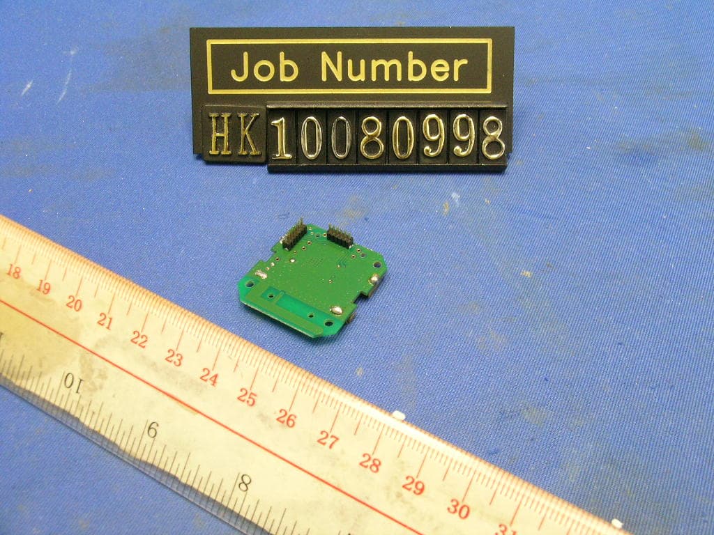
RF7POM0001
Nov 30, 20102.4GHz Transceiver Module
Equipment Class
DXX - Part 15 Low Power Communication Device Transmitter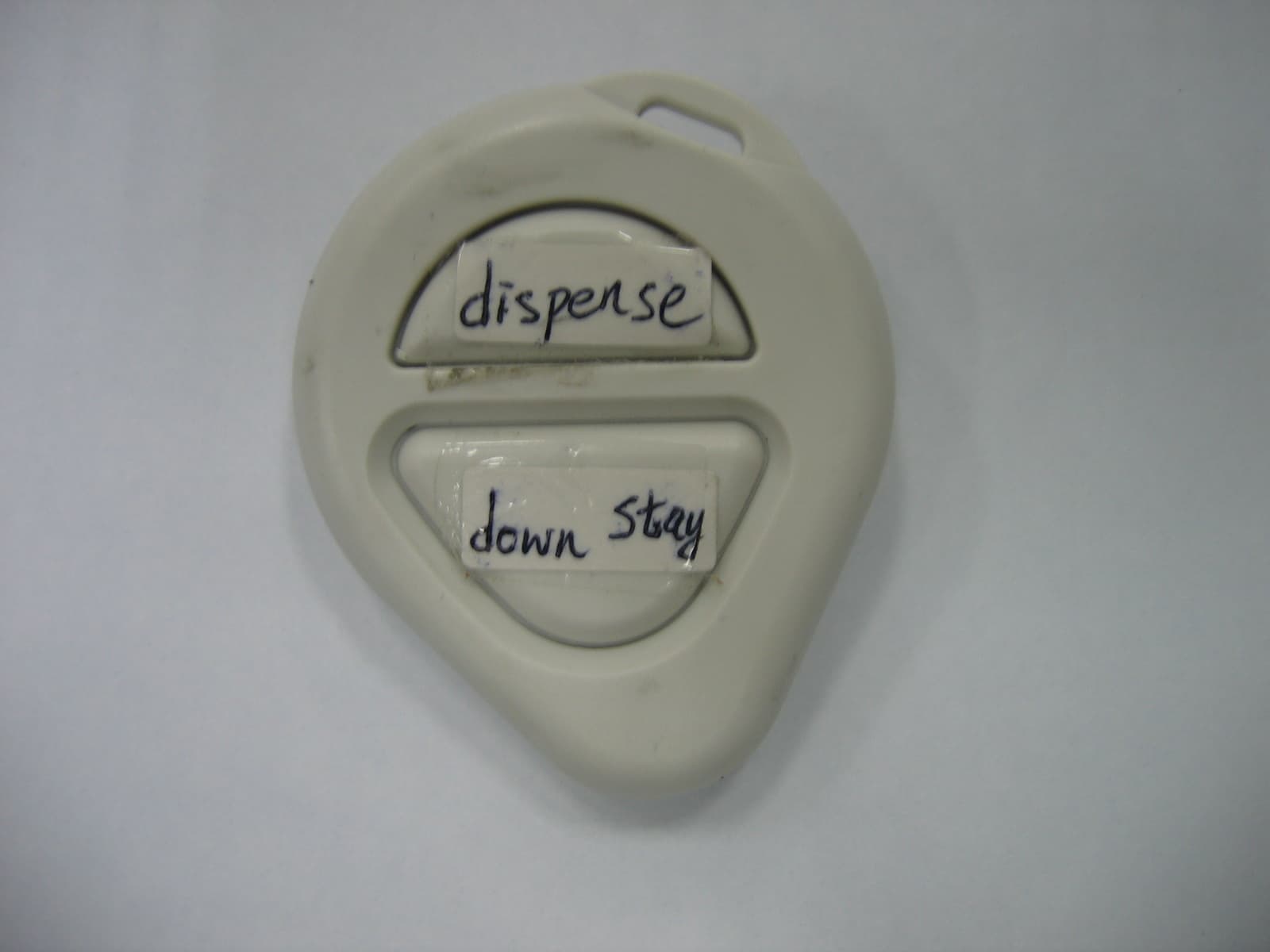
RF7SI398
Dec 21, 2004Dog Training Device
Equipment Class
DSC - Part 15 Security/Remote Control Transmitter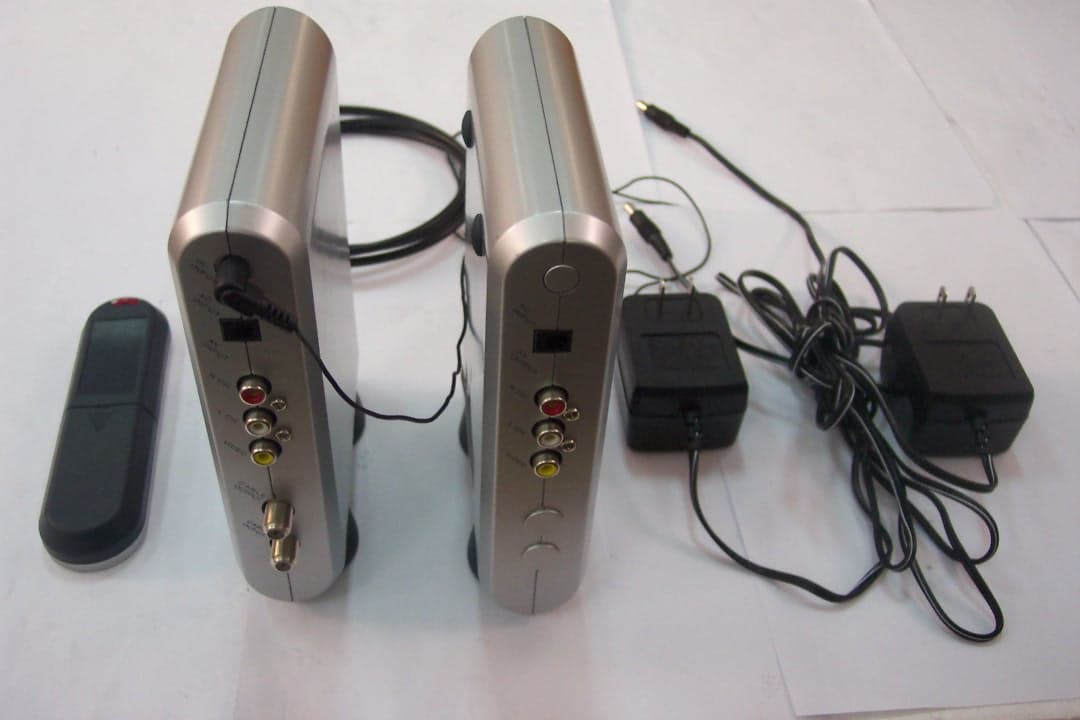
RF7SI670TX
Oct 24, 20042.4GHz TV Transmitter
Equipment Class
DXT - Part 15 Low Power Transceiver, Rx Verified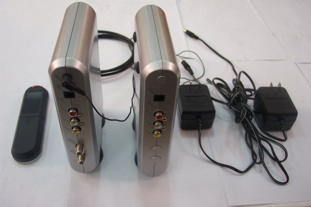
RF7SI670RX
Oct 24, 2004Remote Control
Equipment Class
DSR - Part 15 Remote Control/Security Device Transceiver