RF7WT-2Wireless Transmitter
STL International Ltd.
Click to zoom
Application Details
- Equipment Class
- DXT - Part 15 Low Power Transceiver, Rx Verified
- Date of Grant
- Jun 28, 2004
- Application Purpose
- Original Equipment
- Date of Application
- Jun 28, 2004
- Equipment Note
- Wireless Transmitter
- Frequency Range
- 915.00000000 - 915.00000000
- Company
- STL International Ltd.
- Country
- China
Documents & Files
Document Text
Text extracted from the exhibit documents filed with the FCC. Open a document above to read the original.
Users Manual
Wireless Sentry™ Multiple Bed and Chair Monitoring System Operator’s Manual for Receiver WR-3 Transmitter WT-2 Charger WC-1 Pendant WP-2 Floor Mat WFM-1 Repeater WSR-1 ® UNI VER SAL MED I CAL PROD UCTS, INC. 1620 N. 20 th Circle Lincoln, NE 68503-1103 Tel.: 888 716-0077 (Toll Free) or 718 499-0020 Fax: 732 583-6923 or 718 499-6494 E-Mail: [email protected] WebSite: WWW.U-M-P.COM Table of Contents Introduction·························1 Location of Controls Receiver and Transmitter··············2 Pendant and Repeater················3 Unpacking··························4 Setting Up························5 - 8 Receiver·······················5 Transmitter and Charger·············5 - 6 Pendant·······················6 Wireless Floor Mat··················7 Repeater·····················7 - 8 Programming······················8 - 10 Operation·······················10 - 14 Monitoring by Transmitter·············10 Monitoring by Pendant···············10 Checking for Programmed Locations·······11 Erasing a Programmed Location··········11 Erasing a Repeater Programmed into the Receiver·11 Alarm Signals at the Receiver·········11 - 12 Alarm Signals at the Transmitter··········12 Resetting an Active Alarm Signal·········12 Turning Off Alert Signals··············12 Out-of Range Monitoring··············13 Battery-Low Indication···············13 Charging a Transmitter············13 - 14 Transmitter Logout and Standby Mode······14 Safety Instructions: Transmitter Battery Pack·······15 FCC Warning ·······················16 Radio Frequency Interference···············16 Limited Warranty·····················17 Introduction The Wireless Sentry is a comprehensive multi-patient monitoring system designed to alert care givers at a central location. Using 900 MHz spread-spectrum digital technology, this completely wireless system provides extended range performance for up to sixteen locations. The system utilizes five main components – the 16-Station Receiver unit, the Wireless Transmitter with Charging Cradle (Charger), the Wireless Pendant, the Wireless Repeater and the Wireless Floor Mat. (The last three items are optional.) The Wireless Sentry system can monitor fall-prone residents from a bed or wheelchair and includes an “out-of-range” warning alert that sounds if the resident leaves a predetermined safe area. The Transmitter WT-2 is a resident-monitoring device, powered by rechargeable batteries (included), that can be programmed into the Receiver WR-3, which is located at the nurses’ station. Monitoring pads are available for use with the Transmitter for wheelchair and bed applications. The optional Pendant WP-2 is a small, battery-operated device, about the size of a stopwatch, that can be programmed just like a Transmitter. It can then either hang on a cord around the resident’s neck or be strapped on the wrist. When the resident needs assistance, he or she presses a large button on the Pendant, and a silent signal is sent to the Receiver at the nurses’ station. The optional Floor Mat WFM-1 is equipped with its own programmable transmitter and is placed beside a patient’s bed. When weight is placed on the mat, the transmitter sends an alerting signal to the Receiver. The optional Repeater WSR-1 is a device, shaped like a Receiver, that is placed on a wall or other convenient location between the Transmitter (or Pendant or Floor Mat) and the Receiver. It boosts the signal from the Transmitter, effectively extending its range. 1 Location of Controls 2 3 Wireless Pendant (WP-2) Repeater (WSR-1) Battery Compartment (on back of unit) LED Alarm Button Unpacking In the carton marked Wireless Sentry™ Receiver Model WR-3, you should find the following items: 1 Receiver unit (WR-3) 1 Pedestal 2 wall-mounting screws 1 AC Adapter with cable 1 Index Card 1 Set of Instructions In the carton marked Wireless Sentry™ Transmitter Model WT-2, you should find the following items: 1 Transmitter unit (WT-2) with rechargeable battery installed 1 Charging Cradle (WC-1) 1 AC Adapter with cable 1 Set of Instructions The Wireless Pendant™ Model WP-2 carton should contain the following: 1 Wireless Pendant (WP-2) 1 adjustable Velcro wrist strap 1 looped cord for neck wear 1 Set of Instructions In the carton marked Wireless Floor Mat™ Model WFM-1, you should find: 1 29½” x 17½” plastic mat (WFM-1) 1 transmitter unit with short connecting cable 1 Set of Instructions In the carton marked Wireless Repeater™ Model WSR-1, you should find: 1 Repeater unit (WSR-1) 1 Pedestal 2 wall-mounting screws 1 AC Adapter with cable 1 Set of Instructions If anything is missing or damaged, or if you wish to purchase new or replacement items, contact UMP Customer Service at the following numbers: Tel. : 888 716-0077 (Toll Free) or 718 499-0020 Fax: 732 583-6923 or 718 499-6494 4 Setting Up Receiver Setup 1.Plug the adapter cable into the back of the Receiver, then plug the adapter into the wall outlet. 2.Turn on the unit by pressing the POWER button. The red LED power indicator will go on. 3.. Program the Receiver as described below under Programming. Station Index Card: Use your fingernail or a coin to remove the clear plastic cover from the front of the Receiver. Then, on the Card, write in the room number and/or name of the resident to be assigned to each Transmitter, Pendant or Floor Mat. Replace cover. Locating the Receiver on a Wall or Desk: Once the Receiver has been programmed, it can be placed on the wall by inserting the two keyhole slots on the back onto the studs of a telephone wall plate. Alternately, you can put two screws (included) or nails into a convenient spot on the wall, with one screw located 2¾” above the other. The screws or nails should extend 3/16” from the wall so that the keyhole slots on the back of the Receiver can be slipped over them. The Receiver can also be set up on a desk or counter by attaching the back of the unit to the plastic Pedestal that is included in the packaging of the unit. This sets the unit at a convenie…
Text truncated - open the document above for the full version.
External Photos
FCC ID No.: RF7WT-2 Report No.: 04.05.0995EF Page: 10 of 12 SGS-CSTC Standards Technical Services Ltd. 6 Photographs - EUT Constructional Details
ID Label/Location Info
Applicant: STL INTERNATIONAL LTD FCC ID: RF7WT-2 Proposed Label Location on EUT EUT Rear View/Proposed FCC Mark Location FCC ID: RF7WT-2
Internal Photos
FCC ID No.: RF7WT-2 Report No.: 04.05.0995EF Page: 11 of 12 SGS-CSTC Standards Technical Services Ltd. FCC ID No.: RF7WT-2 Report No.: 04.05.0995EF Page: 12 of 12 SGS-CSTC Standards Technical Services Ltd.
Operational Description
FCC ID: RF7WT-2 WT-2 Wireless Alarm Transmitter Principle of Operation The WT-2 Wireless Alarm Transmitter monitors the state of a connected sentry mat. When the pressure on the mat is released the WT-2 will sound a local alarm and at the same time sends a signal to the WR-3 or WR-4 Receiver. The transmitter will also send a signal in response to the polling signal from the WR-3, or WR-4 Receiver every 60 seconds. This serves to indicate that the transmitter is within communication range from the Receiver. The RF transmitter is a ChipCon CC1000 RF transeiver chip. The chip is programmed to work at 915Mhz ISM band and data rate is approximately 1K baud. Data is encoded in Manchester format. The logic functions are controlled by a Holtek HT46R23 micro controller unit (MCU) which communicates with the RF chip via IIC bus. The MCU is normally in Sleep mode for power saving purpose. When the button is pressed, a signal will generate an interrupt to wake up the MCU. The MCU will then send out an alarm signal with an unique ID code to the Alarm Receiver. For every 60 seconds the MCU will also wake up by action of a watchdog timer and wait for the polling from the Receiver for the out of range polling signal.
Test Report
Report No.: 04.05.0995EF Page: 1 of 12 FCC ID: RF7WT-2 Authorized Signature: Kent Hsu Laboratory Manager This report refers to the General Conditions for Inspection and Testing Services, printed overleaf This report details the results of the testing carried out on one sample. The results contained in this test report do not relate to other samples of the same product and does not permit the use of the SGS PRODUCT CERTIFICATION MARK.. The manufacturer should ensure that all products in series production are in conformity with the product sample detailed in this report. This report may only be reproduced and distributed in full. If the product in this report is used in any configuration other than that detailed in the report, the manufacturer must ensure the new system complies with all relevant standards. Any mention of SGS International Electrical Approvals or testing done by SGS International Electrical Approvals in connection with, distribution or use of the product described in this report must be approved by SGS International Electrical Approvals in writing. The report must not be used by the client to claim product certification, approval, or endorsement by NVLAP, NIST, or any agency of the federal government. All test results in this report can be traceable to National or International Standards. Member of the SGS Group (Société Générale de Surveillance) SGS-CSTC Standards Technical Services Ltd. 1/F., Building No. 1 Building, Agriculture Machinery Materials Co. Wushan Road, Shipai, Tianhe District,Guangzhou, China Telephone: +86 (0) 20 3848 1001 Fax: +86 (0) 20 3848 1006 [email protected] FEDERAL COMMUNICATIONS COMMISSION Registration number: 282399 FCC TEST REPORT Application No. : 04.05.0995E Applicant : STL INTERNATIONAL LTD FCC ID : RF7WT-2 Fundamental Frequency : 915 MHz Equipment under Test (EUT): Name : WIRELESS TRANSMITTER Model : WT-2 Standards : FCC PART 15, SUBPART C : 2003 (Section 15.249) Date of Receipt : 10 May 2004 Date of Test : 26 to 27 May 2004 Date of Issue : 03 June 2004 Test Result : PASS * * In the configuration tested, the EUT complied with the standards specified above. FCC ID No.: RF7WT-2 Report No.: 04.05.0995EF Page: 2 of 12 SGS-CSTC Standards Technical Services Ltd. 2 Contents Page 1 COVER PAGE.........................................................................................................................................................1 2 CONTENTS .............................................................................................................................................................. 2 3 GENERAL INFORMATION.................................................................................................................................. 3 3.1 CLIENT INFORMATION....................................................................................................................................... 3 3.2 DETAILS OF E.U.T. ............................................................................................................................................ 3 3.3 DESCRIPTION OF SUPPORT UNITS....................................................................................................................... 3 3.4 TEST LOCATION................................................................................................................................................. 3 3.5 OTHER INFORMATION REQUESTED BY THE CUSTOMER...................................................................................... 3 3.6 TEST FACILITY................................................................................................................................................... 4 4 TEST RESULTS....................................................................................................................................................... 5 4.1 TEST INSTRUMENTS........................................................................................................................................... 5 4.2 E.U.T. OPERATION............................................................................................................................................ 5 4.3 TEST PROCEDURE & MEASUREMENT DATA....................................................................................................... 6 4.3.1 Radiated Emissions ...................................................................................................................................... 6 4.3.2 Band Edges................................................................................................................................................... 8 5 PHOTOGRAPHS - RADIATED EMISSION TEST SETUP............................................................................... 9 6 PHOTOGRAPHS - EUT CONSTRUCTIONAL DETAILS .........................................................................10-12 FCC ID No.: RF7WT-2 Report No.: 04.05.0995EF Page: 3 of 12 SGS-CSTC Standards Technical Services Ltd. 3 General Information 3.1 Client Information Applicant: STL INTERNATIONAL LTD Address of Applicant: TUNG KONG INDUSTRIAL ZONE.LIU MEI VILLAGE,YUEN ZHOU,BOLOU,PRC 3.2 Details of E.U.T. Product Name: WIRELESS TRANSMITTER Model: WT-2 Power Supply: 3.6V DC Ni-Cd Rechargerable Batteries Power Cord: N/A- 3.3 Description of Support Units The EUT was tested as an independent unit: a 915MHz radio transmitter. 3.4 Test Location All tests were performed at:- SGS-CSTC Standards Technical Services Ltd., Guangzhou Safety & EMC Laboratory, 1/F, Building No. 1, Agriculture Machinery Materials Company Warehouse Ltd., Wushan Road Shipai, Tianhe District, Guangzhou, China. P.C. 510630. Tel: +86 20 3848 1001 Fax: +86 20 3848 1006 3.5 Other Information Requested by the Customer None. FCC ID No.: RF7WT-2 Report No.: 04.05.0995EF Page: 4 of 12 SGS-CSTC Standards Technical Services Ltd. 3.6 Test Facility The test facility is recognized, certified, or accredited by the following organizations: • NVL…
Text truncated - open the document above for the full version.
Test Setup Photos
FCC ID No.: RF7WT-2 Report No.: 04.05.0995EF Page: 9 of 12 SGS-CSTC Standards Technical Services Ltd. 5 Photographs - Radiated Emission Test Setup
Contact Information
Applicant
Esa Chiau(Assistant Marketing Manager)
Test Firm
SGS-CSTC Standards Technical Services Co., LtdJerry Chan
Technical Specifications
| # | Rule Parts | Frequency Range | Power Output |
|---|---|---|---|
| 1 | 15C | 915 MHz - 915 MHz | - |
Other Applications from STL International Ltd.

RF7-RX5-TX2
Jul 07, 2013Remote Controller
Equipment Class
DSC - Part 15 Security/Remote Control Transmitter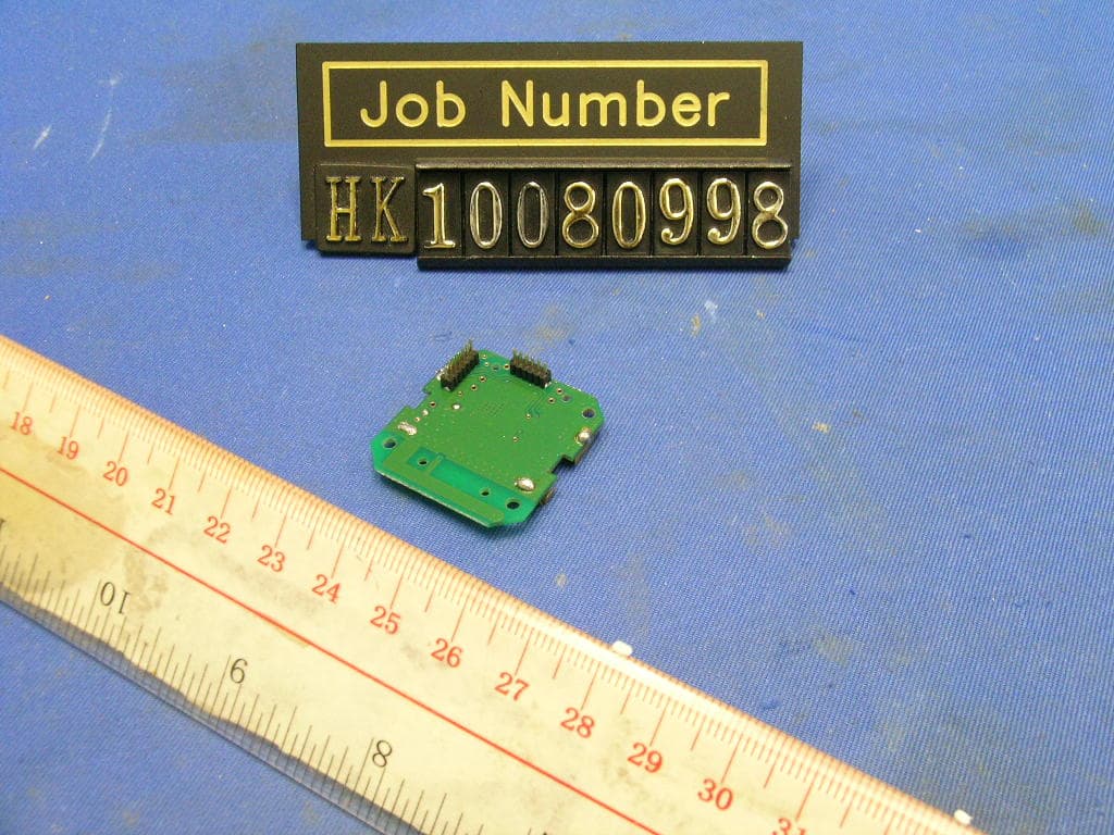
RF7POM0001
Nov 30, 20102.4GHz Transceiver Module
Equipment Class
DXX - Part 15 Low Power Communication Device Transmitter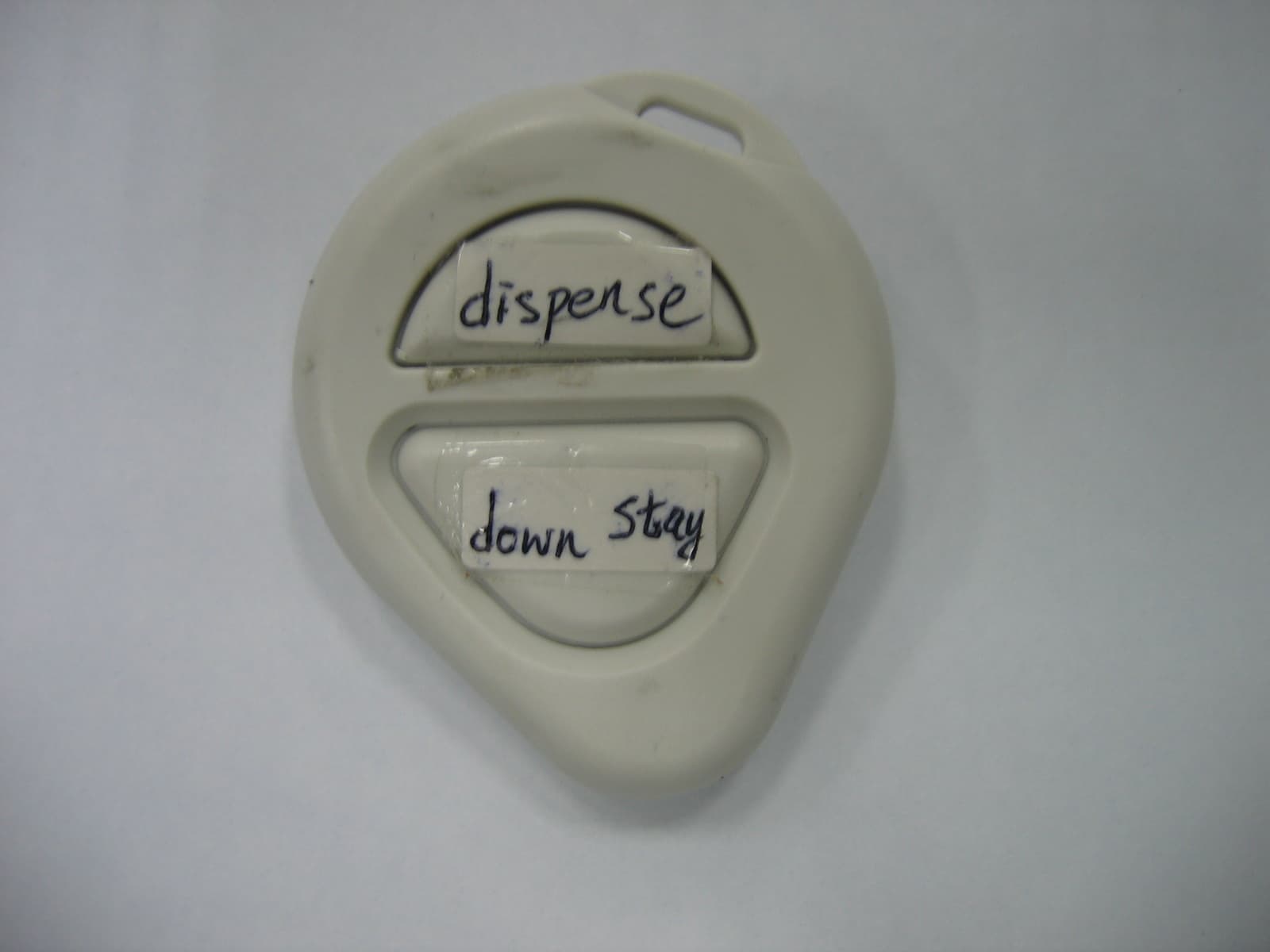
RF7SI398
Dec 21, 2004Dog Training Device
Equipment Class
DSC - Part 15 Security/Remote Control Transmitter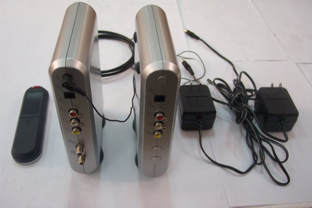
RF7SI670TX
Oct 24, 20042.4GHz TV Transmitter
Equipment Class
DXT - Part 15 Low Power Transceiver, Rx Verified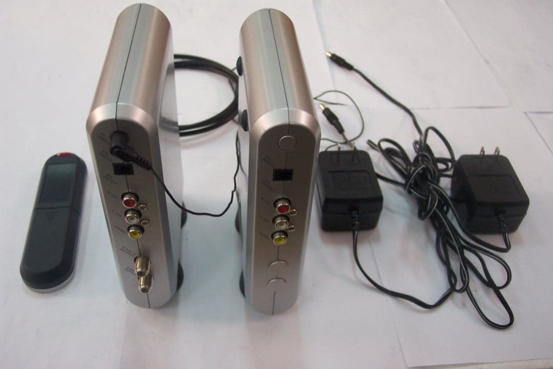
RF7SI670RX
Oct 24, 2004Remote Control
Equipment Class
DSR - Part 15 Remote Control/Security Device Transceiver