RFK-CHA819Multichannel Power amplifier
Intelligent Wireless Products Inc.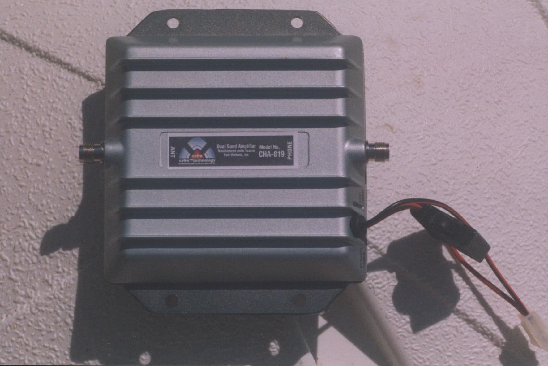
Click to zoom
Application Details
- Equipment Class
- PCB - PCS Licensed Transmitter
- Date of Grant
- Jun 14, 2006
- Application Purpose
- Original Equipment
- Date of Application
- Jun 14, 2006
- Equipment Note
- Multichannel Power amplifier
- Frequency Range
- 869.00000000 - 894.00000000
- Country
- United States
Documents & Files
Document Text
Text extracted from the exhibit documents filed with the FCC. Open a document above to read the original.
Users Manual
Dual Band CHA-819 Amplifier Installation Manual Page 1 of 2 All brands and trademarks are the property of their respective owners. Copyright 2003, Janizary Holdings, Inc. All rights reserved. Rev G D00000515 Designed and manufactured in North America Manufactured under license from Motorola Inc. Note: Before installing the Cyfre™ Amplifier, please read the entire contents of this manual. Section # 1 Parts List Item Qty Description 1 1 Cyfre TM Signal Amplifier 2 1 2 Meter (78”) DC Power Cable Section # 2 Tools and Other Materials Required Item Description 1 Electric drill (as required for signal amplifier mounting holes) 2 Screw driver 3 Qty 4 screws (length and type as required for signal amplifier mounting) 4 Wire cutters / strippers 5 Qty 2 wire connection insulators or insulating material (as required for DC power cable connection to 12V DC system) Section # 3 WARNINGS! ∇ Directly wired vehicle antennas, mounted a minimum distance of 20 cm (7.87 inches) away from the body of any user or nearby persons is recommended. ∇ Mounting an amplifier in the engine cavity or on the underside of the vehicle will void the manufacturer’s warranty. ∇ Subjecting the amplifier to voltages greater than 30 Volts DC will damage the amplifier and void the manufacturer’s warranty. ∇ Any vehicle with an electrical system of greater than 30 Volts DC should use a step-down voltage regulator to bring the voltage within the DC operating power range of the amplifier (10 to 30V dc). ∇ Under no circumstances should the amplifier be powered up without a properly connected 50 ohm 800/1900 MHz dual band cellular/PCS antenna or the amplifier may be damaged, resulting in the manufacturer’s warranty being void. ∇ For optimum performance and compatibility with cellular service provider requirements, it is recommended that an external antenna with a maximum gain of 3dB be installed. ∇ Use of cellular amplifiers with antennas of higher gains than 3 dB gain is in violation of FCC regulations for which the offender will be fully liable, and warranty claims will be voided. It is recommended that only certified automotive installation technicians install this product in a vehicle. Installation by any other person is at the risk of the vehicle owner and operator. Section # 4 Installation: Selecting a Suitable Location To Mount The Signal Amplifier Locate a suitable place to mount and conceal the signal amplifier. Suggested mounting locations include: under the dashboard, under the seat, or in the trunk. For peak performance the signal amplifier should be mounted as close to the phone handset as possible. The amplifier’s location should be easily accessible and mounted away from moving parts, as well as excessive heat and moisture. Dual Band CHA-819 Amplifier Installation Manual Page 2 of 2 All brands and trademarks are the property of their respective owners. Copyright 2003, Janizary Holdings, Inc. All rights reserved. Rev G D00000515 Designed and manufactured in North America Manufactured under license from Motorola Inc. Section # 5 Installation Cautions ∇ Use caution to avoid drilling through or near fuel lines or fuel tanks; brake lines; or electrical wiring. ∇ Do not mount the amplifier or its associated wiring in a location that may interfere with the safe operation of the vehicle. ∇ If the fuse is changed from the 3 amps to a higher rating the warranty is void. Purchaser of the amplifier would be responsible for the repair of the unit. ∇ Caution: Connection to the negative side with the positive lead will cause damage to the amplifier. Section # 6 Installation Of The Signal Amplifier To meet the FCC Exposure Guidelines, the antenna should be installed so there is at least 20 cm of separation between the body of the user or nearby persons and the antenna. Typical Installation For Under The Seat Mounting 1. For safety, disconnect the vehicle’s negative “−“ battery terminal to remove power from the vehicle. 2. Drill holes and mount the signal amplifier (ITEM 1) in the selected location. 3. Connect the red wire of the supplied 2 Meter (78”) power cable (ITEM 2) for the signal amplifier to a positive connection on the vehicle’s electrical system. Choose a 10 to 30 Volt DC circuit that is: fuse protected; and ignition switched. (Often referred to as the “Accessory output”) 4. Attach the solid black wire of the supplied 2 Meter (78”) power cable (ITEM 2) to a vehicle electrical ground point. 5. Attach an external antenna cable (7dbi max) to the amplifier's antenna connector. The “Phone” connector on the amplifier is connected to a cellular phone handset via a RF cradle or an RF cable. You may also connect the optional RF cable for your handset, from the cellular handset to amplifier port labelled “Phone”. 6. Reconnect the vehicle’s negative “−“ Battery terminal. Section # 7 Limited Warranty Cyfre™ warrants that this product is free from any defects in material or workmanship for a period of one year. If a defect in material or workmanship is found, Cyfre™ agrees to repair or replace the product at its own discretion, free of charge to the original purchaser. Please return the product along with proof of purchase to the original authorized dealer. This warranty is null and void if the product has been modified, abused, tampered with, subjected to abnormal conditions, if the fuse is changed to a higher rating than 3 amp, or transferred to someone other than the original purchaser. Use a 3dB antenna for Optimal Performance
Cover Letter(s)
LEON PAUL KASS, LLC CONSULTANT IN WIRELESS COMMUNICATION 9695 135 th Street Seminole, Florida 33776-1434 Phone 727-593-3100 Fax 727-593-7950 E Mail lpk @ fdn.com June 16, 2006 FEDERAL COMMUNICATIONS COMMISSION Office of Engineering and Technology Equipment Authorization Division 7435 Oakland Mills Road Columbia, MD 21046 Re: PERMANENT CONFIDENTIALITY REQUEST FOR FCC ID:RFK-CHA819 Model CHA819 Dear Sir/ Madam: Pursuant to sections 0.457 and 0.459 of CFR 47, the applicant requests permanent confidential treatment of the following information accompanying this application. 1. Block Diagram 2. Parts List 3. Schematic drawing 4. Theory of operation 5. Tune up procedure The above materials contain trade secrets and proprietary information in conjunction with a Manufacturing Agreement between Janizary Holdings, Inc., and Leon Paul Kass LLC that is in conjunction with a License Agreement between Leon Paul Kass, LLC and Motorola, Inc. to use specific patented technology from Motorola, Inc. in the development and production of this unit. The public disclosure of these matters might be harmful to the applicant and provide unjustified benefits to its competitors. Sincerely Leon Paul Kass Authorized Agent for Janizary Holdings, Inc.
Cover Letter(s)
American Telecommunications Certification Body Inc. 6731 Whittier Ave, McLean, VA 22101 May 30, 2006 RE: FCC ID: RFK-CHA819_ATCB003517 Attention: Leon Paul Kass I have a few comments on this Application. Please note that further comments may arise in response to answers provided to the questions below. 1. Please provide internal photos that show both sides of all boards. 2. Please provide a separate tune up procedure. If tune up is not done on this device, please provide a statement to that affect. 3. Please note that the PCS band has F1D, GXW, DXW, F9W emissions designators while the Cell band has F1D, GXW, DXW emissions designator. Please confirm that F9W is not included in the 824MHz band. 4. Please note that the test report RV48085A-004 is dated Feb 2006. It appears to be a revision of a report dated as far back as Jan 2004. Please note that the FCC does not accept data for reports more than one year old. Please state the relevance of any data in the report that is more than one year old. 5. Please note that the test report RV48085A-004 is dated Feb 2006. Please note that the list of calibrated equipment show calibration due date prior to Feb 2006. Please also note that both TIA603 and ANSI C63.4 state that measurements are to be done using equipment with current calibration. This means that all of the equipment used in the Feb 2006 report is out of calibration. Please provide a report using currently calibrated equipment as required by the accepted FCC test methods. 6. Please note that the resolution bandwidth for measuring power of the CDMA signal in the PCS band was set to 10kHz. Please note that the FCC has stated that no measurements of licensed devices for BW or power can be made with a res bandwidth of less than 1% of the emissions bandwidth. Please note that a CDMA emissions bandwidth is typically 1M25 (or 1250kHz). This would mean that the minimum res bandwidth allowed for measurement purposes would be 12.5kHz. Please provide channel power measurements under a condition where the res band width is not less than 1% of the emission bandwidth. Alternately, as these type analyzers are supposed to determine a proper 1% bandwidth, please explain how the analyzer determines the auto res bw function and why the res bandwidth is not 1% or more of the measured emission bandwidth as is supposed to be. 7. Please note that the FCC has stated that for Occupied Bandwidth measurements the resolution bandwidth shall not be less than 1% of the emission bandwidth. Please note that the emission bandwidth for the CDMA signals in the report is stated to be 1.26MHz. This would be a res bw of 12.6kHz or GREATER. Please provide occupied bandwidth measurement data using the acceptable FCC guidelines of 1% or greater res bw. 8. Please note that in the procedure for unwanted emissions the report states that it subtracts the gain on the antenna. Please note that the gain of the antenna is to be added to that of the signal generator output not subtracted. Also please note that the results table does not provide any information for the antenna gain or cable loss. Please explain and please correct as necessary. 9. Please note that part 22 spurious emissions is an ERP limit while part 24 spurious emissions is an EIRP limit. Please note that the test results do not clearly identify if the results are ERP or EIRP. Please correct the report to show the proper units. 10. Please note that spurious emissions for all bands is necessary. This means that both the uplink and downlink bands for both part 22 and part 24 must be provided. The report only appears to show spurious emissions data for the uplink 824MHz band and the uplink 1850MHz band. Please provide the missing downlink bands for part 22 and part 24. z Page 2 May 30, 2006 Dennis Ward mailto:[email protected] The items indicated above must be submitted before processing can continue on the above referenced application. Failure to provide the requested information may result in application termination. Correspondence should be considered part of the permanent submission and may be viewed from the Internet after a Grant of Equipment Authorization is issued. Please do not respond to this correspondence using the email reply button. In order for your response to be processed expeditiously, you must submit your documents through the AmericanTCB.com website. Also, please note that partial responses increase processing time and should not be submitted. Any questions about the content of this correspondence should be directed to the sender.
RF Exposure Info
FCC ID: RFK-CHA819 194 RF Exposure The CHA-819 (800 / 1900 MHz) dual band RF Compensator is operated as a mobile device as defined in 2.1091(b) bases on its design and installation. The compensator is installed into a vehicle such that it is physically secured and is generally located more than 20 cm from the end- user. This information is included in the user manual. It is suggested that the antenna be installed such that there is at least 20 cm of separation between the occupants of the vehicle and the antenna. The CHA-819 (800 / 1900 MHz) dual band RF Compensator has a transmitted conducted power of 0.5 W in both cellular and PCS bands. The mobile antenna supplied with the transceiver has a maximum gain of 3 dB, and minimum cable loss of –1.0 dB, together resulting in a maximum EIRP of 1 W. Since the transmit cellular band (824-849 MHz) is below 1.5 GHz and its EIRP with the supplied antenna is below 1.5 and transmit PCS band (1850-1910 MHz) is above 1.5 GHz and its EIRP with the supplied antenna is below 3W, the 800 / 1900 MHz RF Compensator is categorically excluded from routine environmental evaluation per 2.1091(c). FCC ID: RFK-CHA819 195 RF Exposure – MPE Calculations Input Transmitter Power: 1315 mW Antenna Gain: 3 dB Cable loss: 1 dB @ 824 – 849 MHz 2 dB @ 1850 – 1910 MHz Frequency range: 824-849 MHz and 1850-1910 MHz Assumptions 1. A single ¼ wavelength radiating antenna is assumed. 2. Closest exposure distance is assumed to be 20 cm FCC ID: RFK-CHA819 196 RF Exposure – MPE Calculations Calculations The following results shall be assumed to be accurate for the far-field only. These predictions will over-estimate power density in the near–field. Based on the use of a ¼ wavelength radiator, a distance of 20 cm is considered to be in the far-field for all cases. S = PG/4*PI*R 2 @ 824 – 849 MHz P is 1315 mW G is 2 dB (Antenna gain – loss) or 10 (2/10) or 1.585 R is 20 cm S = 0.415 mW/cm 2 For Occupational/Controlled Exposure From 300 to 1500 MHz, power density limit is f/300 mW/cm 2 @ 824 MHz, power density limit is 2.75 mW/cm 2 for 6 minutes. For General Population/Uncontrolled Exposure From 300 to 1500 MHz, power density limit is f/1500 mW/cm 2 @ 824 MHz, Power density limit is 0.55 mW/cm 2 for 30 minutes. Conclusion: Meets MPE limits @ 1850 – 1910 MHz P is 1315 mW G is 1 dB (Antenna gain – loss) or 10 (1/10) or 1.26 R is 20 cm S = 0.329516 mW/cm 2 For Occupational/Controlled Exposure From 1,500 to 100,000 MHz, power density limit is 5 mW/cm 2 for 6 minutes. For General Population/Uncontrolled Exposure From 1,500 to 100,000 MHz, power density limit is 1 mW/cm 2 for 30 minutes. Conclusion: Meets MPE limits
Test Report
FCC ID: RFK-CHA819 1 Application for Certification For an RF amplifier Janizary Holdings Inc. 5330 Derry Ave, Suite F Agoura Hills, CA 91301 RF amplifier FCC ID: RFK-CHA819 IC ID: IC5252A-CHA819 REPORT # RV48085A-005 This report was prepared in accordance with the requirements of the FCC Rules and Regulations Part 2, Subpart J, 2.1031 through 2.1057, and Parts 22, 24, and 90 and in accordance with Industry Canada Radio Standards Specification RSS-131 for Zone Enhancers and any other applicable sections of the rules as indicated herein. Prepared By: DNB Engineering, Inc. 5969 Robinson Avenue Riverside, Ca 92503-8620 Industry Canada Lab Code: IC 4738 13 Jun 2006 FCC ID: RFK-CHA819 2 TEST LAB PERSONNEL Test Performed by: Date Signature Thomas Elders 12 Feb 2006 APPROVALS Management Approval Date Signature Les Payne Sr. Engineering Manager 12 Feb 2006 APPROVALS Revision Revied Date Signature Les Payne Sr. Engineering Manager 13 Jun 2006 Original report RV48085A-001 Dated 20 Jan 2004 Revised report RV48085A-002 Dated 10 Feb 2004 Revised report RV48085A-003 Dated 06 Dec 2004 (inclusion of IC) Revised report RV48085A-004 Dated 06 Feb 2006 (Re-test) Revised report RV48085A-005 Dated 12 Jun 2006 (Re-test) FCC ID: RFK-CHA819 3 TABLE OF CONTENTS Section Title Sheet # Test Lab Personnel and Approvals 2 Table of Contents 3 Table of Figures 4 1.0 ADMINISTRATIVE DATA 5 1.1 Certifications and Qualifications 5 1.2 Measurements and Repeatability Information 5 1.3 Test Methodology 6 1.4 Test Equipment 6 1.5 Deviations 6 1.6 Test Description 7 Note: Paragraph numbers in this report follow the application section numbers found in the FEDERAL COMMUNICATIONS COMMISSION Rules and Regulations, Part 2, Subpart J for Certification of electronic equipment. 2.1033 (C) (1) Application for Certification 8 2.1033 (C) (2) FCC Identifier 9 2.1033 (C) (3) Installation and Operating Instructions (Service manual) 9 2.1033 (C) (4) Type of Emissions 9 2.1033 (C) (5) Frequency Range 9 2.1033 (C) (6) Operating Power 9 2.1033 (C) (7) Maximum Power Allowed in Applicable part(s) of the Rules 9 2.1033 (C) (8) Final RF amplifier Input Power Characteristics 9 2.1033 (C) (9) Tune Up Procedure 9 2.1033 (C) (10) Schematic Diagram and Circuit Description 10 2.1033 (C) (11) Equipment Identification Plate 10 2.1033 (C) (12) Equipment Photographs (Internal) 10 2.1033 (C) (12) Equipment Photographs (External) 10 2.1033 (C) (13) Digital Modulation Techniques 10 2.1033 (C) (14) Test Data 10 Test Set-Up 11-12 2.1046 (RSS-131 cl4.3) Measurement of RF Power Output 13-25 2.1049 (RSS-131 cl4.4) Measurement of Occupied Bandwidth 26-86 2.1051 (RSS-131 cl4.5) Spurious Emissions at Antenna Terminals 87-100 2.1053 Measurement of Field Strength of Spurious Radiation 101-103 Radiated Emissions 104-105 2.1055 (RSS-131 cl4.5) Measurement of Frequency Stability 106 2.1057 Frequency Spectrum to be Investigated 107 RF Exposure 108-110 Appendix A Photographs 115-115 FCC ID: RFK-CHA819 4 TABLE OF FIGURES Figure 1 : Test Equipment 6 Figure 2 : Test Result Summary 10 Figure 3 : Test Set Up Block Diagram 12 Figure 4 : Block Diagram Radiated Emissions 12 Figure 5 : Output Power Plots 14 Figure 6 : Occupied Bandwidth / Modulation Characteristic Plots 27 Figure 7 : Antenna Conducted Spurious Plots 88 Figure 8 : Radiated Spurious Tabular Data 102 Figure 9 : Unintentional Radiated Emissions 105 Appendix A : Photos 111 FCC ID: RFK-CHA819 5 1.0 ADMINISTRATIVE DATA 1.1 Certifications and Qualifications I certify that DNB Engineering, Inc conducted the tests performed in order to obtain the technical data presented in this application. Also, based on the results of the enclosed data, I have concluded that the equipment tested meets or exceeds the requirements of the Rules and Regulations governing this application. 1.2 Measurement Repeatability Information The test data presented in this report has been acquired using the guidelines set forth in FCC Part 2.1031 through 2.1057, and Parts 22, 24,and 90. Also included in this report is compliancy data for Industry Canada RS-131 for Zone Enhancers. The test results presented in this document are valid only for the equipment identified herein under the test conditions described. Repeatability of these test results will only be achieved with identical measurement conditions. These conditions include: The same test distance, EUT Height, Measurement Site Characteristics, and the same EUT System Components. The system must have the same Interconnecting Cables arranged in identical placement to that in the test set-up, with the system and/or EUT functioning in the identical mode of operation (i.e. software and so on) as on the date of the test. Any deviation from the test conditions and the environment on the date of the test may result in measurement repeatability difficulties. All changes made to the EUT during the course of testing as identified in this test report must be incorporated into the EUT or identical models to ensure compliance with the FCC regulations. C. L. Payne III (Para. 1.1) Sr Engineering Manager DNB Engineering, Inc. Tel. (951) 637-2630 Fax (991) 637-2704 E-mail [email protected] FCC ID: RFK-CHA819 6 1.3 Test Methodology The tests were performed in accordance with FCC Part 2 Subpart J, 2.1031 through 2.1057, 15, and 22, 24, 90, Industry Canada RSS-131 on a sample of the production model. 1.4 Test Equipment FIGURE 1: TEST EQUIPMENT Description Manufacturer M/N S/N Cal Date Test Used On Signal Generator Agilent E4432B GB40051213 09/24/05 RF Power Out put, Emissions Lim, Cond Spur, Rad Spur, CE Signal Generator Marconi 2024 112231/034 02/02/06 RF Power Out put, Emissions Lim, Cond Spur, Rad Spur, CE Spectrum Analyzer Display H/P 85662A 259101-1 01/10/06 RF Power Out put, Emissions Lim, Cond Spur, Rad Spur, CE Spectrum Analyzer H/P 8566B 259101-2 01/10/06 RF Power Out put, Emissions Lim, Cond Spur, Rad Spur, CE Quasi-Peak Adapter H/P 85650A 2043A00184 01/10/06 RE Bicon Antenna AH Systems SAS-200/540 524 12/26/05 RE …
Text truncated - open the document above for the full version.
Test Report
FCC ID: RFK-CHA819 101 FIGURE 6: OCCUPIED BANDWIDTH 5969 Robinson Avenue Riverside, CA 92503 (951) 637-2630 FAX (951) 637-2704 Modulation Characteristics DNB Job Number: 68061 (previous 48085) Date: 7 Feb 2006 Customer: Janizary Holdings Inc Model Number: CHA-819 Serial Number: RF amplifier Description: Downlink GSM 1930.275 MHz - Output Conformance Standards [X] IC RSS-131 [X] FCC Part 22 [X] FCC Part 24 [X] FCC Part 90 FCC ID: RFK-CHA819 102 FIGURE 6: OCCUPIED BANDWIDTH 5969 Robinson Avenue Riverside, CA 92503 (951) 637-2630 FAX (951) 637-2704 Occupied Bandwidth DNB Job Number: 68061 (previous 48085) Date: 7 Feb 2006 Customer: Janizary Holdings Inc Model Number: CHA-819 Serial Number: RF amplifier Description: Downlink GSM 1960 MHz Conformance Standards [X] IC RSS-131 [X] FCC Part 22 [X] FCC Part 24 [X] FCC Part 90 FCC ID: RFK-CHA819 103 FIGURE 6: OCCUPIED BANDWIDTH 5969 Robinson Avenue Riverside, CA 92503 (951) 637-2630 FAX (951) 637-2704 Modulation Characteristics DNB Job Number: 68061 (previous 48085) Date: 7 Feb 2006 Customer: Janizary Holdings Inc Model Number: CHA-819 Serial Number: RF amplifier Description: Downlink GSM 1960 MHz - Input Conformance Standards [X] IC RSS-131 [X] FCC Part 22 [X] FCC Part 24 [X] FCC Part 90 FCC ID: RFK-CHA819 104 FIGURE 6: OCCUPIED BANDWIDTH 5969 Robinson Avenue Riverside, CA 92503 (951) 637-2630 FAX (951) 637-2704 Modulation Characteristics DNB Job Number: 68061 (previous 48085) Date: 7 Feb 2006 Customer: Janizary Holdings Inc Model Number: CHA-819 Serial Number: RF amplifier Description: Downlink GSM 1960 MHz - Output Conformance Standards [X] IC RSS-131 [X] FCC Part 22 [X] FCC Part 24 [X] FCC Part 90 FCC ID: RFK-CHA819 105 FIGURE 6: OCCUPIED BANDWIDTH 5969 Robinson Avenue Riverside, CA 92503 (951) 637-2630 FAX (951) 637-2704 Occupied Bandwidth DNB Job Number: 68061 (previous 48085) Date: 7 Feb 2006 Customer: Janizary Holdings Inc Model Number: CHA-819 Serial Number: RF amplifier Description: Downlink GSM 1989.725 MHz Conformance Standards [X] IC RSS-131 [X] FCC Part 22 [X] FCC Part 24 [X] FCC Part 90 FCC ID: RFK-CHA819 106 FIGURE 6: OCCUPIED BANDWIDTH 5969 Robinson Avenue Riverside, CA 92503 (951) 637-2630 FAX (951) 637-2704 Modulation Characteristics DNB Job Number: 68061 (previous 48085) Date: 7 Feb 2006 Customer: Janizary Holdings Inc Model Number: CHA-819 Serial Number: RF amplifier Description: Downlink GSM 1989.725 MHz - Input Conformance Standards [X] IC RSS-131 [X] FCC Part 22 [X] FCC Part 24 [X] FCC Part 90 FCC ID: RFK-CHA819 107 FIGURE 6: OCCUPIED BANDWIDTH 5969 Robinson Avenue Riverside, CA 92503 (951) 637-2630 FAX (951) 637-2704 Modulation Characteristics DNB Job Number: 68061 (previous 48085) Date: 7 Feb 2006 Customer: Janizary Holdings Inc Model Number: CHA-819 Serial Number: RF amplifier Description: Downlink GSM 1989.725 MHz - Output Conformance Standards [X] IC RSS-131 [X] FCC Part 22 [X] FCC Part 24 [X] FCC Part 90 FCC ID: RFK-CHA819 108 FIGURE 6: OCCUPIED BANDWIDTH 5969 Robinson Avenue Riverside, CA 92503 (951) 637-2630 FAX (951) 637-2704 Occupied Bandwidth DNB Job Number: 68061 (previous 48085) Date: 7 Feb 2006 Customer: Janizary Holdings Inc Model Number: CHA-819 Serial Number: RF amplifier Description: Downlink TDMA 869.040 MHz Conformance Standards [X] IC RSS-131 [X] FCC Part 22 [X] FCC Part 24 [X] FCC Part 90 FCC ID: RFK-CHA819 109 FIGURE 6: OCCUPIED BANDWIDTH 5969 Robinson Avenue Riverside, CA 92503 (951) 637-2630 FAX (951) 637-2704 Modulation Characteristics DNB Job Number: 68061 (previous 48085) Date: 7 Feb 2006 Customer: Janizary Holdings Inc Model Number: CHA-819 Serial Number: RF amplifier Description: Downlink TDMA 869.040 MHz - Input Conformance Standards [X] IC RSS-131 [X] FCC Part 22 [X] FCC Part 24 [X] FCC Part 90 FCC ID: RFK-CHA819 110 FIGURE 6: OCCUPIED BANDWIDTH 5969 Robinson Avenue Riverside, CA 92503 (951) 637-2630 FAX (951) 637-2704 Modulation Characteristics DNB Job Number: 68061 (previous 48085) Date: 7 Feb 2006 Customer: Janizary Holdings Inc Model Number: CHA-819 Serial Number: RF amplifier Description: Downlink TDMA 869.040 MHz - Ouputt Conformance Standards [X] IC RSS-131 [X] FCC Part 22 [X] FCC Part 24 [X] FCC Part 90 FCC ID: RFK-CHA819 111 FIGURE 6: OCCUPIED BANDWIDTH 5969 Robinson Avenue Riverside, CA 92503 (951) 637-2630 FAX (951) 637-2704 Occupied Bandwidth DNB Job Number: 68061 (previous 48085) Date: 7 Feb 2006 Customer: Janizary Holdings Inc Model Number: CHA-819 Serial Number: RF amplifier Description: Downlink TDMA 881.5 MHz Conformance Standards [X] IC RSS-131 [X] FCC Part 22 [X] FCC Part 24 [X] FCC Part 90 FCC ID: RFK-CHA819 112 FIGURE 6: OCCUPIED BANDWIDTH 5969 Robinson Avenue Riverside, CA 92503 (951) 637-2630 FAX (951) 637-2704 Modulation Characteristics DNB Job Number: 68061 (previous 48085) Date: 7 Feb 2006 Customer: Janizary Holdings Inc Model Number: CHA-819 Serial Number: RF amplifier Description: Downlink TDMA 881.5 MHz - Input Conformance Standards [X] IC RSS-131 [X] FCC Part 22 [X] FCC Part 24 [X] FCC Part 90 FCC ID: RFK-CHA819 113 FIGURE 6: OCCUPIED BANDWIDTH 5969 Robinson Avenue Riverside, CA 92503 (951) 637-2630 FAX (951) 637-2704 Modulation Characteristics DNB Job Number: 68061 (previous 48085) Date: 7 Feb 2006 Customer: Janizary Holdings Inc Model Number: CHA-819 Serial Number: RF amplifier Description: Downlink TDMA 881.5 MHz - Output Conformance Standards [X] IC RSS-131 [X] FCC Part 22 [X] FCC Part 24 [X] FCC Part 90 FCC ID: RFK-CHA819 114 FIGURE 6: OCCUPIED BANDWIDTH 5969 Robinson Avenue Riverside, CA 92503 (951) 637-2630 FAX (951) 637-2704 Occupied Bandwidth DNB Job Number: 68061 (previous 48085) Date: 7 Feb 2006 Customer: Janizary Holdings Inc Model Number: CHA-819 Serial Number: RF amplifier Description: Downlink TDMA 893.960 MHz Conformance Standards [X] IC RSS-131 [X] FCC Part 22 [X] FCC Part 24 [X] FCC Part 90 FCC ID: RFK-CHA819 115 FIGURE 6: OCCUPIED BANDWIDTH 5969 Robinson Avenue Riverside, CA 92503 (951) 637-2630 FAX (951) 637-2704 Modulation Characteristics DNB…
Text truncated - open the document above for the full version.
Contact Information
Applicant
Leon Paul Kass(Consulting Engineer)
Technical Specifications
| # | Rule Parts | Frequency Range | Power Output | Emission | Tolerance |
|---|---|---|---|---|---|
| 14 | 22H | 869 MHz - 894 MHz | 3.10 mW | DXW | Amp |
Other Applications from Intelligent Wireless Products Inc.

RFK-IVWA819
Apr 15, 2007Cellular & PCS Band Full Duplex Booster
Equipment Class
PCB - PCS Licensed Transmitter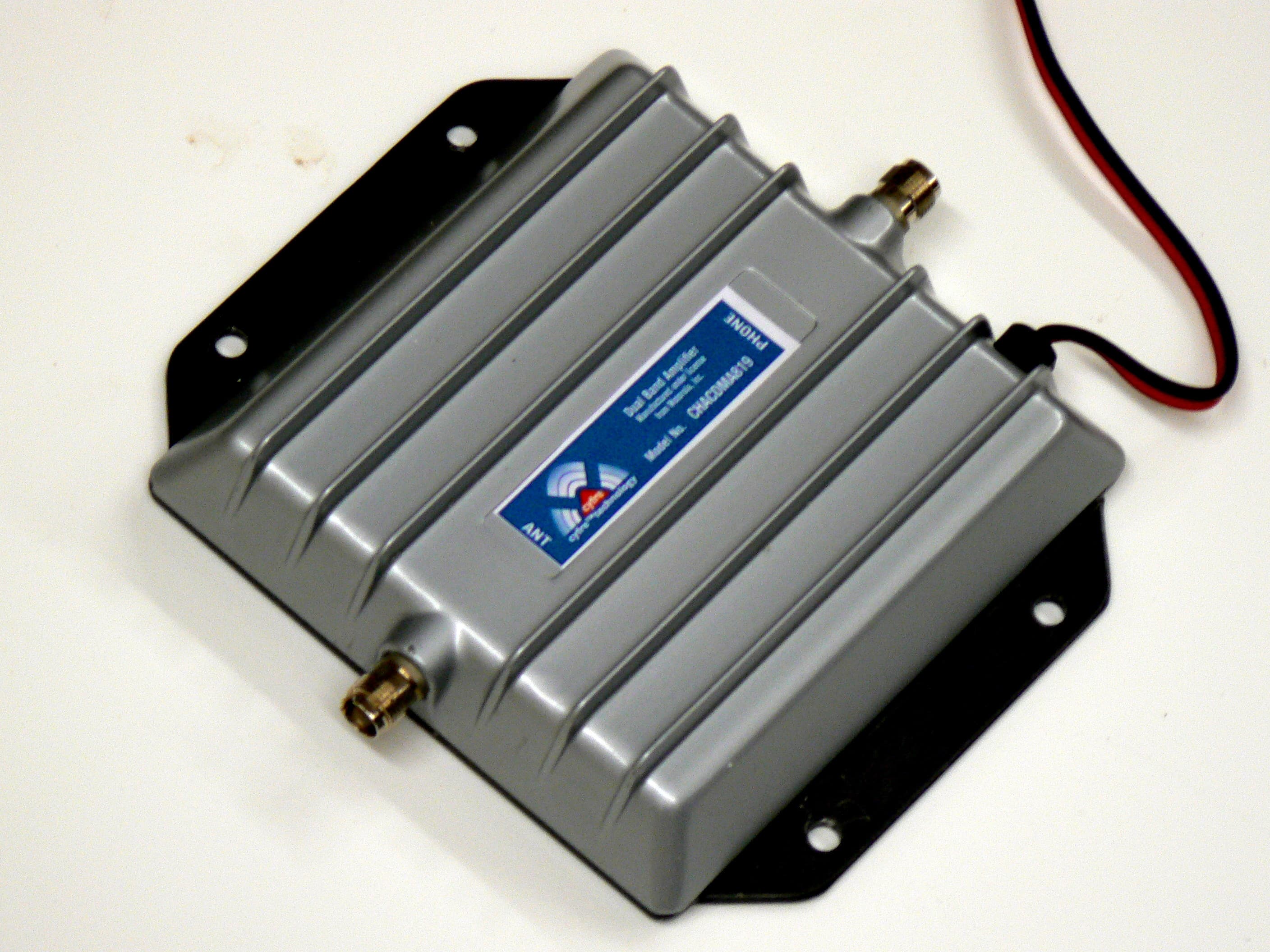
RFKCHACDMA819
Dec 27, 2006Booster / Dual-Band Bi-Directional Amplifier
Equipment Class
AMP - Amplifier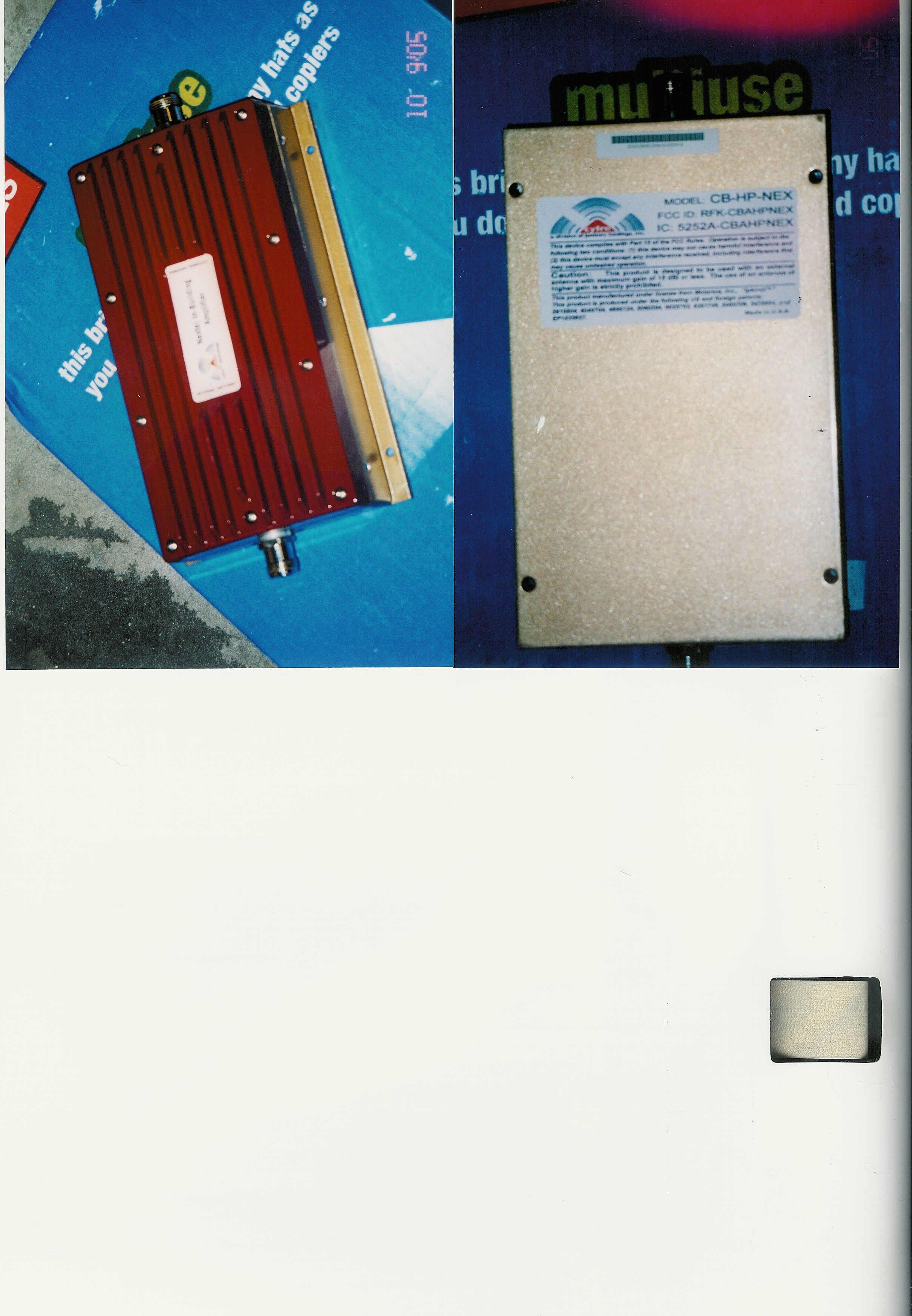
RFK-CBAHPNEX
May 02, 2006Multi Channel Power Amplifier
Equipment Class
TNB - Licensed Non-Broadcast Station Transmitter
RFK-CBAHP800
Jan 08, 2006Single Channel Power Amplifier
Equipment Class
TNB - Licensed Non-Broadcast Station Transmitter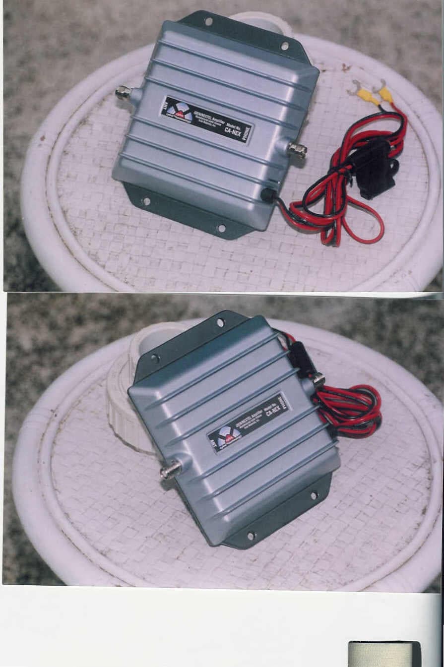
RFK-LMSWDJHNEX
Oct 05, 2004Single Channel Amplifier
Equipment Class
AMP - Amplifier