RFKCHACDMA819Booster / Dual-Band Bi-Directional Amplifier
Intelligent Wireless Products Inc.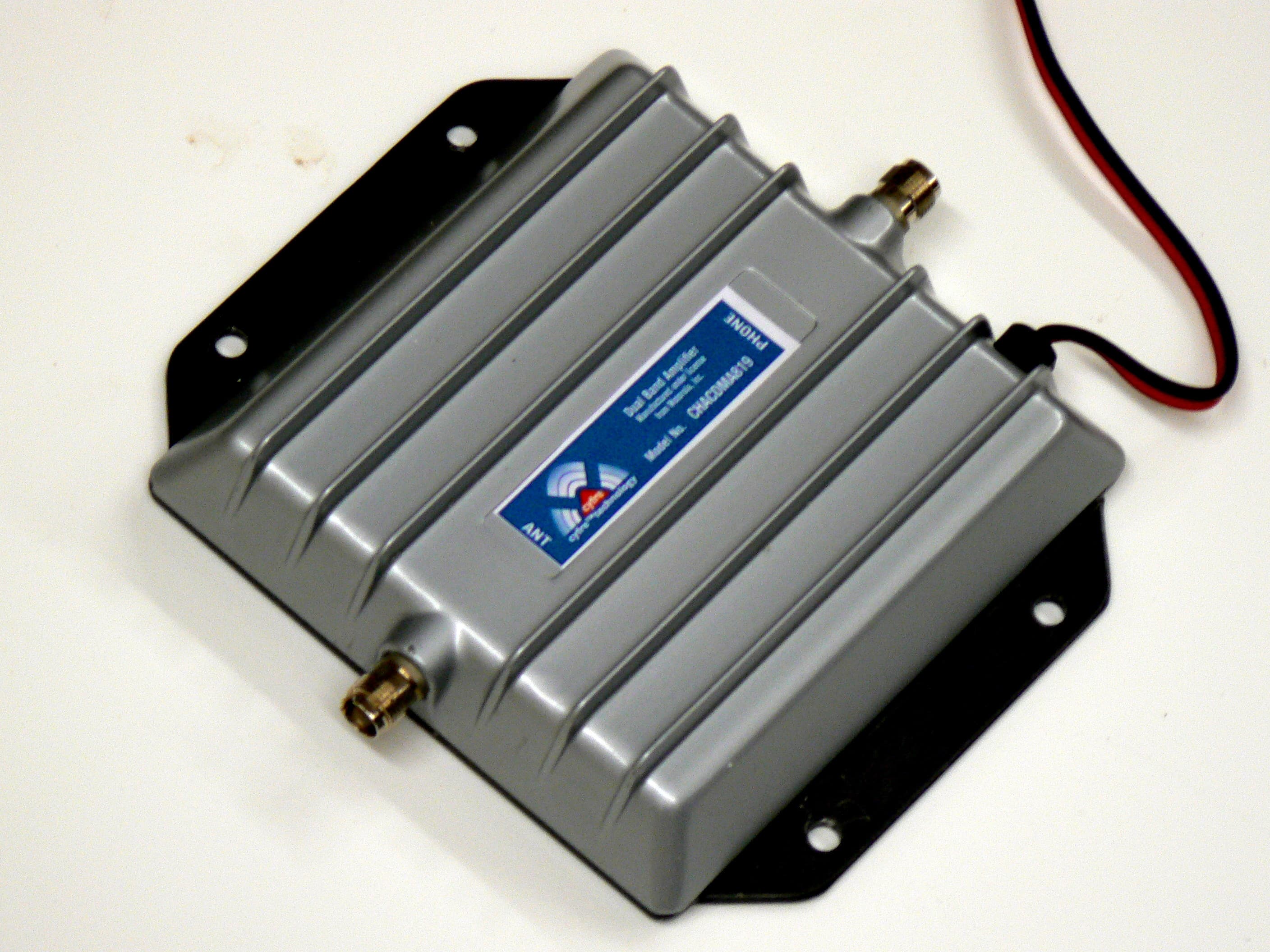
Click to zoom
Application Details
- Equipment Class
- AMP - Amplifier
- Date of Grant
- Dec 27, 2006
- Application Purpose
- Original Equipment
- Date of Application
- Dec 25, 2006
- Equipment Note
- Booster / Dual-Band Bi-Directional Amplifier
- Frequency Range
- 1930.70000000 - 1989.30000000
- Country
- United States
Documents & Files
Document Text
Text extracted from the exhibit documents filed with the FCC. Open a document above to read the original.
Users Manual
Dual Band CHACDMA-819 Amplifier Installation Manual Page 1 of 3 All brands and trademarks are the property of their respective owners. Copyright 2003, Janizary Holdings, Inc. All rights reserved. Rev h D00000515 Designed and manufactured in North America Manufactured under license from Motorola Inc. Note: Before installing the Cyfre™ Amplifier, please read the entire contents of this manual. Section # 1 Parts List Item Qty Description 1 1 Cyfre TM Signal Amplifier 2 1 2 Meter (78”) DC Power Cable Section # 2 Tools and Other Materials Required Item Description 1 Electric drill (as required for signal amplifier mounting holes) 2 Screw driver 3 Qty 4 screws (length and type as required for signal amplifier mounting) 4 Wire cutters / strippers 5 Qty 2 wire connection insulators or insulating material (as required for DC power cable connection to 12V DC system) Section # 3 WARNINGS! ∇ Directly wired vehicle antennas, mounted a minimum distance of 20 cm (7.87 inches) away from the body of any user or nearby persons is recommended. ∇ Mounting an amplifier in the engine cavity or on the underside of the vehicle will void the manufacturer’s warranty. ∇ Subjecting the amplifier to voltages greater than 30 Volts DC will damage the amplifier and void the manufacturer’s warranty. ∇ Any vehicle with an electrical system of greater than 30 Volts DC should use a step-down voltage regulator to bring the voltage within the DC operating power range of the amplifier (10 to 30V dc). ∇ Under no circumstances should the amplifier be powered up without a properly connected 50 ohm 800/1900 MHz dual band cellular/PCS antenna or the amplifier may be damaged, resulting in the manufacturer’s warranty being void. ∇ For optimum performance and compatibility with cellular service provider requirements, it is recommended that an external antenna with a maximum gain of 3dB be installed. ∇ Use of cellular amplifiers with antennas of higher gains than 3 dB gain is in violation of FCC regulations for which the offender will be fully liable, and warranty claims will be voided. It is recommended that only certified automotive installation technicians install this product in a vehicle. Installation by any other person is at the risk of the vehicle owner and operator. Section # 4 Installation: Selecting a Suitable Location To Mount The Signal Amplifier Dual Band CHACDMA-819 Amplifier Installation Manual Page 2 of 3 All brands and trademarks are the property of their respective owners. Copyright 2003, Janizary Holdings, Inc. All rights reserved. Rev h D00000515 Designed and manufactured in North America Manufactured under license from Motorola Inc. Locate a suitable place to mount and conceal the signal amplifier. Suggested mounting locations include: under the dashboard, under the seat, or in the trunk. For peak performance the signal amplifier should be mounted as close to the phone handset as possible. The amplifier’s location should be easily accessible and mounted away from moving parts, as well as excessive heat and moisture. Section # 5 Installation Cautions ∇ Use caution to avoid drilling through or near fuel lines or fuel tanks; brake lines; or electrical wiring. ∇ Do not mount the amplifier or its associated wiring in a location that may interfere with the safe operation of the vehicle. ∇ If the fuse is changed from the 3 amps to a higher rating the warranty is void. Purchaser of the amplifier would be responsible for the repair of the unit. ∇ Caution: Connection to the negative side with the positive lead will cause damage to the amplifier. Section # 6 Installation Of The Signal Amplifier To meet the FCC Exposure Guidelines, the antenna should be installed so there is at least 20 cm of separation between the body of the user or nearby persons and the antenna. Typical Installation For Under The Seat Mounting 1. For safety, disconnect the vehicle’s negative “−“ battery terminal to remove power from the vehicle. 2. Drill holes and mount the signal amplifier (ITEM 1) in the selected location. 3. Connect the red wire of the supplied 2 Meter (78”) power cable (ITEM 2) for the signal amplifier to a positive connection on the vehicle’s electrical system. Choose a 10 to 30 Volt DC circuit that is: fuse protected; and ignition switched. (Often referred to as the “Accessory output”) 4. Attach the solid black wire of the supplied 2 Meter (78”) power cable (ITEM 2) to a vehicle electrical ground point. 5. Attach an external antenna cable (7dbi max) to the amplifier's antenna connector. The “Phone” connector on the amplifier is connected to a cellular phone handset via a RF cradle or an RF cable. You may also connect the optional RF cable for your handset, from the cellular handset to amplifier port labelled “Phone”. 6. Reconnect the vehicle’s negative “−“ Battery terminal. Section # 7 Limited Warranty Cyfre™ warrants that this product is free from any defects in material or workmanship for a period of one year. If a defect in material or workmanship is found, Cyfre™ agrees to repair or replace the product at its own discretion, free of charge to the Use a 3dB antenna for Optimal Performance Dual Band CHACDMA-819 Amplifier Installation Manual Page 3 of 3 All brands and trademarks are the property of their respective owners. Copyright 2003, Janizary Holdings, Inc. All rights reserved. Rev h D00000515 Designed and manufactured in North America Manufactured under license from Motorola Inc. original purchaser. Please return the product along with proof of purchase to the original authorized dealer. This warranty is null and void if the product has been modified, abused, tampered with, subjected to abnormal conditions, if the fuse is changed to a higher rating than 3 amp, or transferred to someone other than the original purchaser.
Cover Letter(s)
LEON PAUL KASS, LLC CONSULTANT IN WIRELESS COMMUNICATION 9695 135 th Street Seminole, Florida 33776-1434 Phone 727-593-3100 Fax 727-593-7950 E Mail lpk @ fdn.com December 26, 2006 FEDERAL COMMUNICATIONS COMMISSION Office of Engineering and Technology Equipment Authorization Division 7435 Oakland Mills Road Columbia, MD 21046 Re: PERMANENT CONFIDENTIALITY REQUEST FOR FCC ID:RFK-CHACDMA819 Model CHACDMA819 Dear Sir/ Madam: Pursuant to sections 0.457 and 0.459 of CFR 47, the applicant requests permanent confidential treatment of the following information accompanying this application. 1. Block Diagram 2. Parts List 3. Schematic drawing 4. Theory of operation 5. Tune up procedure The above materials contain trade secrets and proprietary information in conjunction with a Manufacturing Agreement between Janizary Holdings, Inc., and Leon Paul Kass LLC that is in conjunction with a License Agreement between Leon Paul Kass, LLC and Motorola, Inc. to use specific patented technology from Motorola, Inc. in the development and production of this unit, and its use with specific Motorola cellular handsets. The public disclosure of these matters might be harmful to the applicant and provide unjustified benefits to its competitors. Sincerely Leon Paul Kass Authorized Agent for Janizary Holdings, Inc.
Cover Letter(s)
American Telecommunications Certification Body Inc. 6731 Whittier Ave, McLean, VA 22101 October 9, 2006 RE: Janizary Holdings, Inc. FCC ID: RFKCHCDMA819 I have a few comments on this Application. Depending on your responses, kindly understand there may be additional comments. 1.) There are no Internal Photographs included in this filing. Please provide Internal Photographs. 2.) I accept the fact that there are no tune-up controls available within this device after manufacturing is complete. However, I have greater difficulty understanding how there are no controls available during manufacturing to assure that RF power and frequency is maintained. Please tell me how this is done. 3.) FYI: If possible, a graph or gain chart of input vs. output RF power would be appreciated for each of the four bands for which Certification is desired. This would greatly aid in my understanding of this device. 4.) I note that your Form 731 does not include an emission designator for either of the Part 22 or Part 24 base station frequency bands. Does this indicate that this device can carry/amplify any base station signal found within 869-894 or 1930-1990 MHz? 5.) Your Test Report appears to indicate that this device may be capable of analog AMPS. Is this true? If so, then appropriate AMPS test data should also be provided. William H. Graff President and Director of Engineering mailto: [email protected] The items indicated above must be submitted before processing can continue on the above referenced application. Failure to provide the requested information may result in application termination. Correspondence should be considered part of the permanent submission and may be viewed from the Internet after a Grant of Equipment Authorization is issued. Please do not respond to this correspondence using the email reply button. In order for your response to be processed expeditiously, you must submit your documents through the AmericanTCB.com website. Also, please note that partial responses increase processing time and should not be submitted. Any questions about the content of this correspondence should be directed to the sender.
Cover Letter(s)
American Telecommunications Certification Body Inc. 6731 Whittier Ave, McLean, VA 22101 October 18, 2006 RE: Janizary Holdings, Inc. FCC ID: RFKCHCDMA819 I have a few comments on this Application. Depending on your responses, kindly understand there may be additional comments. 1.) I believe we may have had a mis-communication about the gain chart. I was hoping to understand the gain of the device as it was varied in input power to output power. My reasoning has to do with understanding the rated power of this amplifier device across all bands of operation. Ideally, I would want a mid-channel within each of the 824-849, and 1850- 1910 MHz bands to be varied in 2 or 3dB steps from the lowest power setting to the highest power level before compression takes place. It is not an FCC requirement in the strictest sense, but it does aid in my understanding of how this device functions. 2.) Your revised Tune Up description indicates there are “pass-fail” power output criteria for accepting a device from production. What I am looking for is what are those target levels? At what power is a device acceptable for each of the Part 22 and Part 24 bands? How does the manufacturer insure that the maximum power for 824-848 MHz band will be 1.429W, and for 1850-1910 MHz 1.510 watts? William H. Graff President and Director of Engineering mailto: [email protected] The items indicated above must be submitted before processing can continue on the above referenced application. Failure to provide the requested information may result in application termination. Correspondence should be considered part of the permanent submission and may be viewed from the Internet after a Grant of Equipment Authorization is issued. Please do not respond to this correspondence using the email reply button. In order for your response to be processed expeditiously, you must submit your documents through the AmericanTCB.com website. Also, please note that partial responses increase processing time and should not be submitted. Any questions about the content of this correspondence should be directed to the sender.
Cover Letter(s)
American Telecommunications Certification Body Inc. 6731 Whittier Ave, McLean, VA 22101 December 4, 2006 RE: Janizary Holdings, Inc. FCC ID: RFKCHCDMA819 I have a few comments on this Application. Depending on your responses, kindly understand there may be additional comments. 1.) Your form 731 requests the entire Part 22 uplink band of 824-849 MHz and the entire Part 24 uplink band of 1850-1910 MHz band. It is typical for band edge compliance to follow the standard CDMA channelization frequencies of 824.73 – 848.19 MHz for Part 22 and 1851.25- 1908.75 MHz for Part 24. The band edge compliance data shown in the Test Report is for a narrower subset of each of these bands. Compliance is shown for only 826-847 MHz, and for 1852-1908 MHz. We recommend that band edge compliance be shown for both 824.73 and 848.19 MHz /1851.25 and 1908.75 MHz at the highest rated power requested on Form 731. Either that or demonstrate how this device will not transmit on the lowest and highest CDMA channels used for each band. 2.) Your Canada application form requests 300KGXW. Why are you asking for GSM in Canada? Your application also lists AMPS, but no analog test information is presented. Is this a misprint? 3.) Page 93 of the Test Report claims a maximum conducted RF power of 0.5W is this correct? William H. Graff President and Director of Engineering mailto: [email protected] The items indicated above must be submitted before processing can continue on the above referenced application. Failure to provide the requested information may result in application termination. Correspondence should be considered part of the permanent submission and may be viewed from the Internet after a Grant of Equipment Authorization is issued. Please do not respond to this correspondence using the email reply button. In order for your response to be processed expeditiously, you must submit your documents through the AmericanTCB.com website. Also, please note that partial responses increase processing time and should not be submitted. Any questions about the content of this correspondence should be directed to the sender.
Cover Letter(s)
1 William Graff From: Leon Paul Kass [[email protected]] Sent: Wednesday, November 29, 2006 11:05 PM To: William Graff; [email protected] Cc: [email protected]; [email protected]; [email protected]; [email protected]; [email protected]; Stan; [email protected] Subject: Re: www.AmericanTCB.com ATCB004115 | RFKCHACDMA819 | 5252A - CHACDMA | | RFKCHACDMA819_ATCB004115 Follow Up Flag: Follow up Flag Status: Red 11/29/06 Bill: Less from DNB Engineering, the laboratory that has been doing all of the testing has responded as follows to your request. "I have reviewed Bill's request and have the following comments. Item 1 - This data is already included in the test report. Please reference pages 27,33,36,42,45,51,54,and 60 which is the maximum input at the center frequency and indicates band edges compliance. Item 2 - After reviewing the clause that Bill referenced I have the following comments. This is specific to the output control associated with a programmable CDMA source. As your device is not a CDMA source and is not programmable (no output control function) I am not sure this paragraph is valid. This device should be qualified under RSS-131 Signal boosters with the applicable references to the base standards for the type of signal used, if required. Your device is an amplifier, no controls signal in , signal out, and DC power in. Please verify with Bill what is required. Thanks Les Please let me know what other information you may need so we can wrap up this application. Thank you Leon ----- Original Message ----- From: "William Graff" <[email protected]> To: <[email protected]>; <[email protected]> Cc: <[email protected]>; <[email protected]>; <[email protected]>; <[email protected]> Sent: Wednesday, November 22, 2006 10:15 PM Subject: www.AmericanTCB.com ATCB004115 | RFKCHACDMA819 | 5252A - CHACDMA | | RFKCHACDMA819_ATCB004115 > Regarding www.AmericanTCB.com application: > ATCB ID: ATCB004115 > FCC ID: RFKCHACDMA819 > IC: 5252A - CHACDMA > TCF: > Account name: leonpaulkass > > Please provide band edge data for both the Part 22 and Part 24 bands at the > highest expected input power level for this amplifier. Be sure to justify > this power setting. > > For Canada, please provide evidence that this device will maintain the 2 > minimum controllable power level stated in RSS-129 when the cellphone input > signal drops to -51dBm. > > Best Regards, > > Bill > >
Cover Letter(s)
William Graff From: Generic Office of Engineering Technology [[email protected]] Sent: Friday, December 22, 2006 1:47 AM To: [email protected] Subject: Response to Inquiry to FCC (Tracking Number 750117) 12/27/2006 Inquiry: Gentlemen - I have an application for a Part 22/24 dual-band bi-directionsl subscriber CDMA amplifier for use in automotive applications. The device has a conducted RF uplink Pout of about 1.5W conducted and a downlink RF Pout of about 3mW. Can the Applicant apply for a subset of the Part 22 and part 24 bands instead of the entire band? In other words, can the Applicant sucessfully get a Grant for only 826-847 MHz in Part 22, and 1851.84-1909.16 in Part 24 for the uplink portion of the band? (these frequencies represent the center channels of 1M25F9W emissions) The guidance document provided to TCBs specifies low, mid, and high channels should be tested, but does not say who can define these channels. Your guidance would be greatly appreciated. Bill. Response: If a device doesn't operate across an entire allocated band than a grant listing only the operational frequencies is acceptable. Do not reply to this message. Please select the Reply to an Inquiry Response link from the OET Inquiry System to add any additional information pertaining to this inquiry.
Test Setup Photos
FCC ID: RFK-CHACDMA819 97 PHOTOS: RADIATED EMISSIONS: BICON Notes: FCC ID: RFK-CHACDMA819 98 PHOTOS: RADIATED EMISSIONS: LOG Notes: FCC ID: RFK-CHACDMA819 99 PHOTOS: RADIATED FIELD STRENGTH OF SPURIOUS EMISSIONS Notes: FCC ID: RFK-CHACDMA819 100 PHOTO: RF POWER OUTPUT, EMISSIONS LIMITATIONS CDMA, OCCUPIED BANDWIDTH CDMA, CONDUCTED SPURIOUS EMISSIONS AT ANTENNA TERMINALS Notes:
Contact Information
Applicant
Leon Paul Kass(Consulting Engineer)
Technical Contact
Leon Paul Kass LLCLeon Paul Kass
[email protected]727 593 3100
9695 135th Street · Seminole · United States
Test Firm
DNB Engineering, Inc.Bryan Broaddus
Technical Specifications
| # | Rule Parts | Frequency Range | Power Output | Emission | Tolerance |
|---|---|---|---|---|---|
| 4 | 24E | 1.93 GHz - 1.99 GHz | 1.50 mW | F9W | Amp |
Other Applications from Intelligent Wireless Products Inc.

RFK-IVWA819
Apr 15, 2007Cellular & PCS Band Full Duplex Booster
Equipment Class
PCB - PCS Licensed Transmitter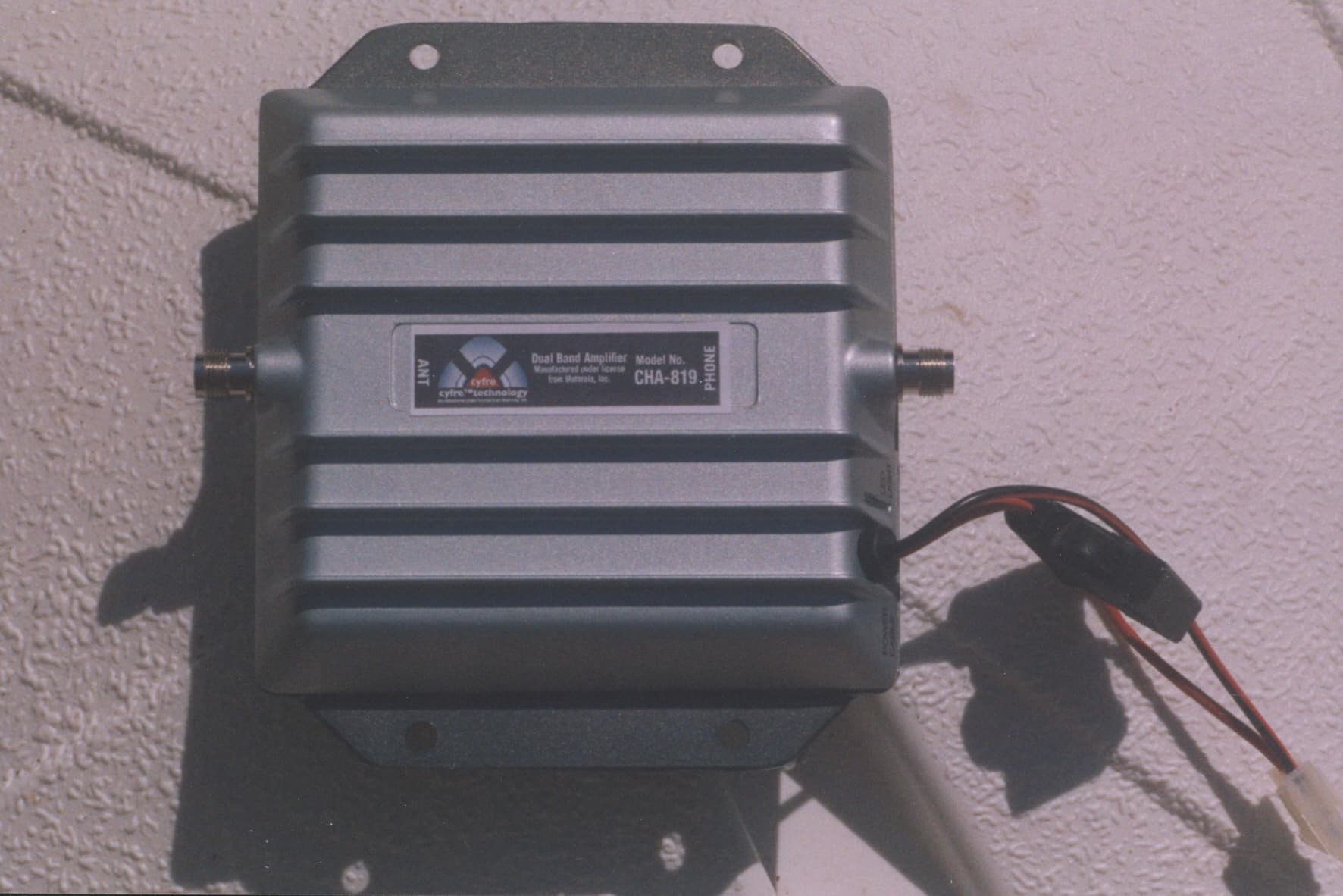
RFK-CHA819
Jun 14, 2006Multichannel Power amplifier
Equipment Class
PCB - PCS Licensed Transmitter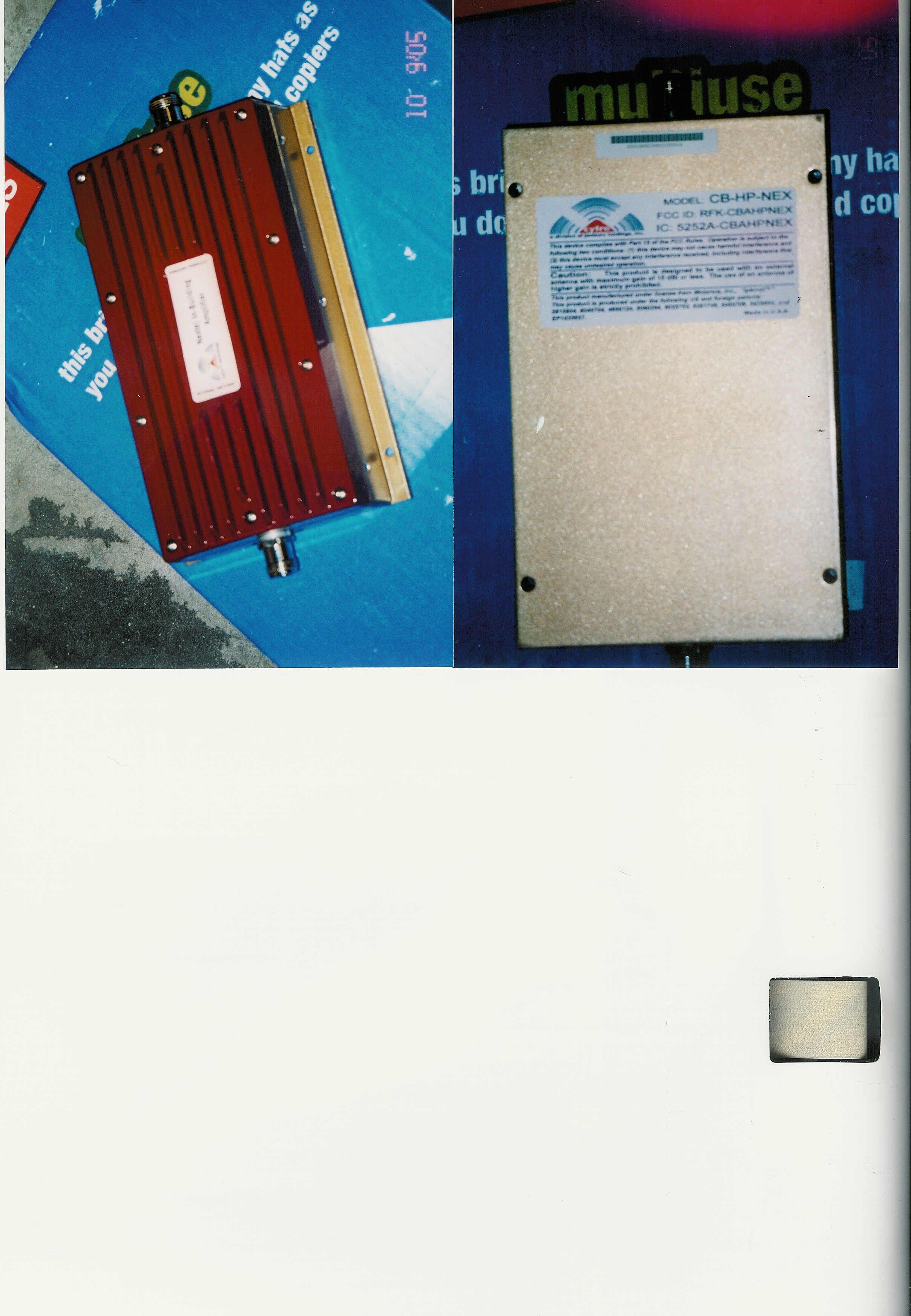
RFK-CBAHPNEX
May 02, 2006Multi Channel Power Amplifier
Equipment Class
TNB - Licensed Non-Broadcast Station Transmitter
RFK-CBAHP800
Jan 08, 2006Single Channel Power Amplifier
Equipment Class
TNB - Licensed Non-Broadcast Station Transmitter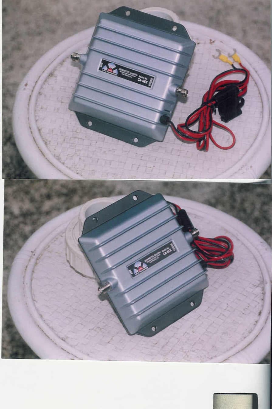
RFK-LMSWDJHNEX
Oct 05, 2004Single Channel Amplifier
Equipment Class
AMP - Amplifier