RGE-CMGSBOF9C1CMG-SBO-H
Comigo Ltd.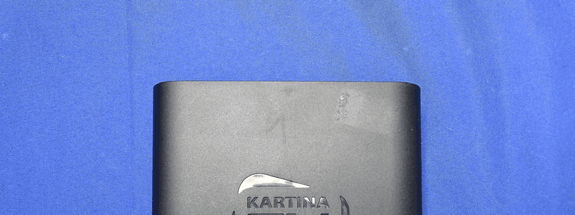
Click to zoom
Application Details
- Equipment Class
- DTS - Digital Transmission System
- Date of Grant
- Apr 15, 2015
- Application Purpose
- Original Equipment
- Date of Application
- Apr 15, 2015
- Equipment Note
- CMG-SBO-H
- Frequency Range
- 2412.00000000 - 2462.00000000
- Company
- Comigo Ltd.
- Country
- Israel
Documents & Files
Document Text
Text extracted from the exhibit documents filed with the FCC. Open a document above to read the original.
Users Manual
Chitram Galaxy HD Quick User Guide What’s in the box? Remote Control (including batteries and a plastic tab) HDMI cable Ethernet cable Power adapter 23 Chitram Galaxy HD Setting up your system HDMI cable: Connect the HDMI cable to Chitram Galaxy HD and to your TV Ethernet cable: If you use a wired network, connect the cable to the Chitram Galaxy HD and to your router. If you use a wireless network you will be able to set it up during the welcome process (see page 8). Power adapter: Connect the power adapter to your Chitram Galaxy HD and to the wall outlet ! Important: the power adapter is the last one to be connected (it should be plugged-in only after the HDMI and the Ethernet cables are plugged-in) Usin g a 3.0mm flat head screw driv er, in sert it in to the ba ery lid slo t St ep : 1 Prepare the remote control: Remove the plastic tab to enable battery contact before 45 Chitram Galaxy HD Remote control navigation buttons content information dashboard of your favorite activities user login socialize with your friends mouse change the channel aspect ratio system menu system information letters / other characters toggles main menu Control SideKeyboard Side Chitram Galaxy HD STBY last TV channel 67 Completing the setup: 1. Turn on your TV, make sure it’s tuned to the same HDMI input your Chitram Galaxy HD is connected to 2. You will either see a “Welcome” screen, or a Comigo logo screen (if so, please wait about one minute for a “Welcome” screen to appear) 3. Continue following the on-screen instructions and you will be able to: • Set up your internet connection • Adjust screen size to your TV * Note: During the initial setup the Chitram Galaxy HD will reset itself. 4. Enter your Chitram TV user information Having trouble completing the guided setup? Check out pages 12-13 Congratulations – you are now connected! Pressing the Up/Down arrows on the 4-way navigation keys of the Remote Control will allow you to view the list of available channels 89 5. Chitram TV setup: • Choose your server • Choose your picture quality (bitrate) • Set necessary time shift • Change code for restricted channels Learn more about Chitram Galaxy HD • Access Multimedia network or on a hard drive connected to your Chitram Galaxy HD: whether it’s music, photos or personal content • Browse the web and enjoy the wide variety of internet based content • Access the VOD library • Access Online Videos to watch videos which were shared by your friends in Facebook • Explore and search for friends or content and other items, • Control and more • Enjoy some Android Apps Please note: Chitram Galaxy HD features are constantly being enhanced and enriched. Therefore, you will always be able to enjoy our new various features and capabilities as will be released from time to time. All you have to do is just keep your Chitram Galaxy HD plugged in and connected to the internet so that it can download the latest software updates automatically. 1011 Troubleshooting on the “Network connection” screen 5. If your network has security-enabled then make sure you input the correct password (case- sensitive) • Changing the remote control batteries: When the batteries are low, replace it with another CR2032 batteries • Cannot connect to your wireless home network during the setup? 1. For Wi-Fi operation you need to ensure that you have at least the minimum required signal strength. If you are not getting 2 or more signal-strength bars in the“wireless network” setup screen, then adjust the location of your Chitram Galaxy HD and/ or the location of your wireless router 2. Make sure there are no obstructions, like cement walls, between your Chitram Galaxy HD and your wireless router 3. Make sure you select “Wireless” and not “Ethernet” on the “Network connection” screen 4. Make sure you select the correct wireless router name • Black screen? Your TV does not display a Comigo screen? Make sure your TV input source matches the physical connection used to connect your Chitram Galaxy HD. Press the Input selection button (also called Source) on your TV or TV Remote to cycle through the various video inputs until you see a Comigo screen. • You cannot see a picture on your TV? 1. Make sure your TV is turned on 2. Make sure all connectors are pushed in properly 3. Make sure that the Chitram Galaxy HD is connected to the power and turned on (front panel LED should be green) Usin g a 3.0mm flat head screw driv er, in sert it in to the ba ery lid slo t St ep : 1 Push toward the remote to open the Ba ery Lid St ep : 2 Usin g a 3.0mm flat head screw driv er, in sert it in to the ba ery lid slo t St ep : 1 Push toward the remote to open the Ba ery Lid St ep : 2 1213 Push toward the remote to St ep : 2 1415 FCC part 15.19: This device complies with Part 15 of the FCC rules. Operation is subject to the following two conditions: (1) this device may not cause harmful interference, and (2) this device must accept any interference received, including interference that may cause undesired operation. FCC ID: RGE-CMGSBOF9C1 FCC part 15.105: NOTE: This equipment has been tested and found to comply with the limits for a Class B digital device, pursuant to Part 15 of the FCC Rules. These limits are designed to provide reasonable protection against harmful interference in a residential installation. This equipment generates, uses, and can radiate radio frequency energy and, if not installed and used in accordance with the instructions, may cause harmful interference to radio communications. However, there is no guarantee that interference will not occur in a particular installation. If this equipment does cause harmful interference to radio or television reception, which can be determined by turning the equipment off and on, the user is encouraged to try to correct the interference by one or more of the following measures: • Reorient or relocate the receiving antenna • Increase the separation between the equipment and receiver • Connect the equipment into an outlet on a cir…
Text truncated - open the document above for the full version.
External Photos
Report No.: 1510452R-RFUSP01V00 Page : 1 of 3 Attachment 2 : EUT Detailed Photographs (1) EUT Photo (2) EUT Photo Report No.: 1510452R-RFUSP01V00 Page : 2 of 3 (3) EUT Photo (4) EUT Photo Report No.: 1510452R-RFUSP01V00 Page : 3 of 3 (5) EUT Photo
ID Label/Location Info
Comigo Ltd. FCC ID.: RGE-CMGSBOF9C1 15 HaPardes St., Yarkona 45915 Israel Tel : +972-9-771-5090 FCC ID Label
ID Label/Location Info
Comigo Ltd. FCC ID.: RGE-CMGSBOF9C1 15 HaPardes St., Yarkona 45915 Israel Tel : +972-9-771-5090 The FCC ID Label will be placed on the equipment as shown in the photograph below.
Internal Photos
Report No.: 1510452R-RFUSP01V00 Page : 1 of 13 Attachment 2 : EUT Detailed Photographs (6) EUT Photo (7) EUT Photo-Antenna Report No.: 1510452R-RFUSP01V00 Page : 2 of 13 (8) EUT Photo (9) EUT Photo Report No.: 1510452R-RFUSP01V00 Page : 3 of 13 (10) EUT Photo (11) EUT Photo WLAN Module Report No.: 1510452R-RFUSP01V00 Page : 4 of 13 (12) EUT Photo (13) EUT Photo Report No.: 1510452R-RFUSP01V00 Page : 5 of 13 (14) EUT Photo (15) EUT Photo Report No.: 1510452R-RFUSP01V00 Page : 6 of 13 (16) EUT Photo (17) EUT Photo Report No.: 1510452R-RFUSP01V00 Page : 7 of 13 (18) EUT Photo (19) EUT Photo Report No.: 1510452R-RFUSP01V00 Page : 8 of 13 (20) EUT Photo (21) EUT Photo Report No.: 1510452R-RFUSP01V00 Page : 9 of 13 (22) EUT Photo (23) EUT Photo Report No.: 1510452R-RFUSP01V00 Page : 10 of 13 (24) EUT Photo (25) EUT Photo Report No.: 1510452R-RFUSP01V00 Page : 11 of 13 (26) EUT Photo (27) EUT Photo Report No.: 1510452R-RFUSP01V00 Page : 12 of 13 (28) EUT Photo (29) EUT Photo Report No.: 1510452R-RFUSP01V00 Page : 13 of 13 (30) EUT Photo
RF Exposure Info
Report No.: 1510452R-RFUSP26V00 Page: 1 of 3 RF Exposure Evaluation declaration Product Name CMG-SBO-H Model No. CMG-SBOF9C FCC ID RGE-CMGSBOF9C1 Applicant Comigo Ltd. Address 15 HaPardes St., Yarkona, Israel, 45915 Date of Receipt Jan. 21, 2015 Date of Declaration Mar. 12, 2015 Report No. 1510452R-RFUSP26V00 The test results relate only to the samples tested. The test results shown in the test report are traceable to the national/international standard through the calibration report of the equipment and evaluated measurement uncertainty herein. This report must not be used to claim product endorsement by TAF or any agency of the government. The test report shall not be reproduced without the written approval of QuieTek Corporation. Report No.: 1510452R-RFUSP26V00 Page: 2 of 3 1. RF Exposure Evaluation 1.1. Limits According to FCC 1.1310: The criteria listed in the following table shall be used to evaluate the environment impact of human exposure to radio frequency (RF) radiation as specified in 1.1307(b) LIMITS FOR MAXIMUM PERMISSIBLE EXPOSURE (MPE) Frequency Range (MHz) Electric Field Strength (V/m) Magnetic Field Strength (A/m) Power Density (mW/cm 2 ) Average Time (Minutes) (A) Limits for Occupational/ Control Exposures 300-1500 -- -- F/300 6 1500-100,000 -- -- 5 6 (B) Limits for General Population/ Uncontrolled Exposures 300-1500 -- -- F/1500 6 1500-100,000 -- -- 1 30 F= Frequency in MHz Friis Formula Friis transmission formula: Pd = (Pout*G)/(4*pi*r 2 ) Where Pd = power density in mW/cm 2 Pout = output power to antenna in mW G = gain of antenna in linear scale Pi = 3.1416 R = distance between observation point and center of the radiator in cm Pd id the limit of MPE, 1 mW/cm 2 . If we know the maximum gain of the antenna and the total power input to the antenna, through the calculation, we will know the distance r where the MPE limit is reached. 1.2. Test Procedure Software provided by client enabled the EUT to transmit and receive data at lowest, middle and highest channel individually. The temperature and related humidity: 18°Cand 78% RH. Report No.: 1510452R-RFUSP26V00 Page: 3 of 3 1.3. Test Result of RF Exposure Evaluation Product : CMG-SBO-H Test Item : RF Exposure Evaluation Test Site : No.3 OATS Operation Frequency 2412-2462MHz Maximum Conducted output power 24.43dBm Antenna gain -0.12dBi Output Power Into Antenna & RF Exposure Evaluation Distance: Output Power to Antenna (mW) Power Density at R = 20 cm (mW/cm2) 277.3320 0.053670 Power density is lower than the limit (1 mW/cm2).
Test Report
Report No. 1510452R-RFUSP26V00 Page : 1 of 91 FCC Test Report Product Name CMG-SBO-H Model No CMG-SBOF9C FCC ID. RGE-CMGSBOF9C1 Applicant Comigo Ltd. Address 15 HaPardes St., Yarkona 45915 Israel Date of Receipt Jan. 21, 2015 Issue Date Mar. 12, 2015 Report No. 1510452R-RFUSP26V00 Report Version V1.0 The test results relate only to the samples tested. The test results shown in the test report are traceable to the national/international standard through the calibration report of the equipment and evaluated measurement uncertainty herein. This report must not be used to claim product endorsement by TAF or any agency of the government. The test report shall not be reproduced without the written approval of QuieTek Corporation. Report No. 1510452R-RFUSP26V00 Page : 2 of 91 Test Report Issue Date: Mar. 12, 2015 Report No.: 1510452R-RFUSP26V00 Product Name CMG-SBO-H Applicant Comigo Ltd. Address 15 HaPardes St., Yarkona 45915 Israel Manufacturer GIGA-BYTE TECHNOLOGY CO., LTD Model No. CMG-SBOF9C FCC ID. RGE-CMGSBOF9C1 EUT Rated Voltage AC 100-240V, 50-60Hz EUT Test Voltage AC 120V/60Hz Trade Name COMIGO Applicable Standard FCC CFR Title 47 Part 15 Subpart C: 2014 ANSI C63.4: 2014, ANSI C63.10: 2013 KDB 558074 D01 DTS Meas Guidance v03r02 Test Result Complied Documented By : ( Senior Adm. Specialist / Joanne Lin ) Tested By : ( Engineer / Benjamin Pan ) Approved By : ( Director / Vincent Lin ) Report No. 1510452R-RFUSP26V00 Page : 3 of 91 TABLE OF CONTENTS Description Page 1. GENERAL INFORMATION .....................................................................................................5 1.1. EUT Description............................................................................................................................5 1.2. Operational Description ................................................................................................................7 1.3. Tested System Details....................................................................................................................8 1.4. Configuration of Tested System ....................................................................................................8 1.5. EUT Exercise Software .................................................................................................................8 1.6. Test Facility .................................................................................................................................10 2. Conducted Emission.................................................................................................................. 11 2.1. Test Equipment............................................................................................................................11 2.2. Test Setup ....................................................................................................................................11 2.3. Limits ..........................................................................................................................................12 2.4. Test Procedure .............................................................................................................................12 2.5. Uncertainty ..................................................................................................................................12 2.6. Test Result of Conducted Emission.............................................................................................13 3. Peak Power Output ...................................................................................................................15 3.1. Test Equipment............................................................................................................................15 3.2. Test Setup ....................................................................................................................................15 3.3. Limits ..........................................................................................................................................15 3.4. Test Procedure .............................................................................................................................15 3.5. Uncertainty ..................................................................................................................................15 3.6. Test Result of Peak Power Output...............................................................................................16 4. Radiated Emission .....................................................................................................................18 4.1. Test Equipment............................................................................................................................19 4.2. Test Setup ....................................................................................................................................20 4.3. Limits ..........................................................................................................................................21 4.4. Test Procedure .............................................................................................................................22 4.5. Uncertainty ..................................................................................................................................22 4.6. Test Result of Radiated Emission................................................................................................23 5. RF antenna conducted test........................................................................................................34 5.1. Test Equipment............................................................................................................................35 5.2. Test Setup ....................................................................................................................................35 5.3. Limits .......…
Text truncated - open the document above for the full version.
Test Setup Photos
Report No.: 1510452R-RFUSP26V00 Page : 1 of 3 Attachment 1: EUT Test Setup Photographs Front View of Conducted Test Back View of Conducted Test Report No.: 1510452R-RFUSP26V00 Page : 2 of 3 Front View of Radiated Test Back View of Radiated Test Report No.: 1510452R-RFUSP26V00 Page : 3 of 3 Front View of Radiated Test (Horn) Back View of Radiated Test (Horn)
Contact Information
Applicant
Motty Lentzitzky
Technical Contact
QuieTek CorporationMaggie Chen
[email protected]886-2-8601-3788
No.5-22, Rueishu Keng, Linkou Dist., · Taiwan
Non-Technical Contact
QuieTek CorporationMaggie Chen
[email protected]886-2-8601-3788
Test Firm
DEKRA TESTING AND CERTIFICATION CO., LTD. LinKouMirenda Liao
Technical Specifications
| # | Rule Parts | Frequency Range | Power Output |
|---|---|---|---|
| 1 | 15C | 2.41 GHz - 2.46 GHz | 280.00 mW |
Other Applications from Comigo Ltd.
RGE-COMIGODUOOTT
Oct 27, 2013IP Set Top Box
Equipment Class
DTS - Digital Transmission System
RGE-COMIGOBOX1
Jan 03, 2013IP Set Top Box
Equipment Class
DTS - Digital Transmission System