RGR40PXIBT502Amplified Controller for BlueTooth Devices
Stillwater Designs and Audio Inc.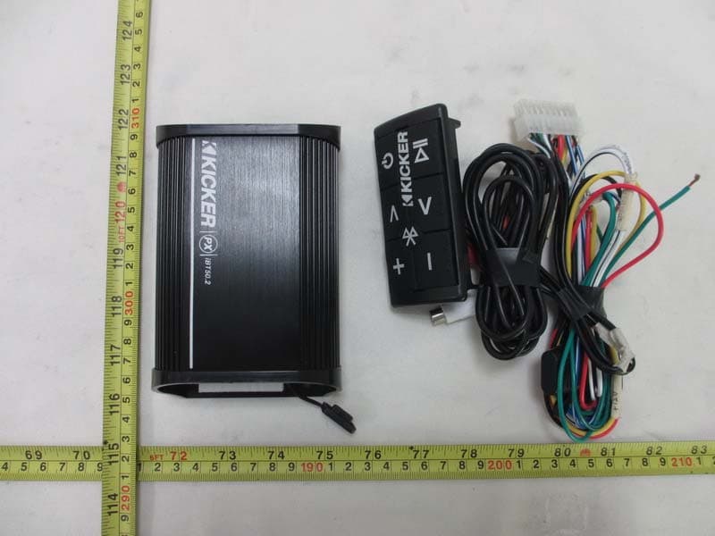
Click to zoom
Application Details
- Equipment Class
- DTS - Digital Transmission System
- Date of Grant
- Apr 02, 2013
- Application Purpose
- Original Equipment
- Date of Application
- Apr 02, 2013
- Equipment Note
- Amplified Controller for BlueTooth Devices
- Frequency Range
- 2402.00000000 - 2480.00000000
- Country
- United States
Documents & Files
Document Text
Text extracted from the exhibit documents filed with the FCC. Open a document above to read the original.
Users Manual
PXiBT50.2 Amplified Controller for BlueTooth ® Devices PXiBT50.2 Mounting: Mount the PXiBT50.2 behind the fairing, underneath the seat, or in another secure location isolated from weather.PXiBT50.2. Montaje: Instale el PXiBT50.2 detrás del fuselaje, debajo del asiento o en otra posición segura aislada del clima. Montage des PXiBT50.2: Installieren Sie den PXiBT50.2 hinter der Verkleidung, unter dem Sitz oder an einem anderen sicheren, wetterfesten Bereich.Installation du PXiBT50.2 : Installez le PXiBT50.2 derrière le capot, sous le siège ou dans un autre emplacement sécurisé, protégé des intempéries. Remote Flush-mounting: Requires custom installation Montaje del mando a distancia al ras: requiere instalación a medidaEinbaumontage der Fernbedienung: (maßgeschneiderte Montage erforderlichInstallation encastrée de la commande à distance : nécessite une installation spécifi que Remote may also be mounted with adhesive.Be careful not to drill into wiring or vehicle mechanisms. You are solely responsible for securely mounting the amplifi er and remote.El mando a distancia también puede ser instalado con un adhesivo.Tenga cuidado de no taladrar el cableado o los mecanismos del vehículo. Usted es el único responsable por la instalación segura del amplifi cador y del mando a distancia. Die Fernbedienung kann auch mit Klebstoff angeklebt werden.Geben Sie acht, dass Sie nicht die Kabel oder Fahrzeugmechanik anbohren. Sie allein sind für die sichere Anbringung des Verstär kers und der Fernbedienung verantwortlich. Le dispositif de commande à distance peut également être installé avec du ruban adhésif.Veillez à ne pas percer le câblage ou les mécanismes du véhicule. Vous êtes entièrement responsable de l’installation sécurisée de l’amplifi cateur et du dispositif de commande à distance. Remote Bar-mounting: The bar mounting clamp may be installed to either the left or right side on the back of the remote.Montaje en barra del control remoto: La abrazadera para montaje en barra puede instalarse en el lado izquierdo o derecho en la parte posterior del control remoto.Montage der Fernbedienungsleiste: Die Montageklemme kann entweder an der linken oder rechten Rückseite der Fernbedienung befestigt werden.Installation de la commande à distance sur un guidon : La bride de fi xation pour le guidon peut être installée sur le côté gauche ou le côté droit à l’arrière de la télécommande. Mounting depth - 18mmProfundidad de montaje - 18mm Montagetiefe - 18mm Profondeur de montage - 18mm Remote Cutout DimensionsRemoto Dimensiones de caladoFern Ausschnitt AbmessungenDimensions de la découpe à distance 86mm 41mm P.O. Box 459 • Stillwater, Oklahoma 74076 • USA • (405) 624–8510 12PXiBT50.2-B-20130320 stillwater designs KICKER products are warranted against defects. Duration and terms of warranty depend on the laws in the country in which it was purchased. For details see your local KICKER Dealer or www.kicker.com/warranty.Our goods come with guarantees that cannot be excluded under the Australian Consumer Law . You are entitled to a replacement or refund for a major failure and for compensation for any other reasonably foreseeable loss or damage. You are als o entitled to have the goods repaired or replaced if the goods fail to be of acceptable quality and the failure does not amount t o a major failure.WARNING: KICKER products are capable of producing sound levels that can permanently damage your hearing! Please use common sense when controlling volume.FCC StatementThis equipment has been tested and found to comply with the limits for a Class B digital device, pursuant to part 15 of the FCC Rules. These limits are designed to provide reasonable protection against harmful interference in a residential installatio n. This equipment generates uses and can radiate radio frequency energy and, if not installed and used in accordance with the instructions, may cause harmful interference to radio communications. However, there is no guarantee that interference will not occur in a particular installation. If this equipment does cause harmful interference to radio or television reception, which c an be determined by turning the equipment off and on, the user is encouraged to try to correct the interference by one or more of the following measures: —Reorient or relocate the receiving antenna.—Increase the separation between the equipment and receiver. —Connect the equipment into an outlet on a circuit different from that to which the receiver is connected. —Consult the dealer or an experienced radio/TV technician for help. FCC StatementThis device complies with FCC radiation exposure limits set forth for an uncontrolled environment.This device complies with Part 15 of the FCC Rules. Operation is subject to the following two conditions: (1) this device may not cause harmful interference, and (2) this device must accept any interference received, including interference that may caus e undesired operation.Caution! Any changes or modifi cations not expressly approved by the party responsible for compliance could void the user’s authority to operate the equipment.Los productos KICKER están garantizados contra defectos. La duración y los términos de la garantía dependen de las leyes del país en donde se realizó la compra. Para más detalles consulte a su distribuidor local de KICKER o visite www.kicker.com/warranty.KICKER-Produkte haben eine Garantie gegen Material- und Verarbeitungsfehler. Dauer und Bedingungen der Garantie hängen von den Gesetzen des Landes ab, in dem sie erworben wurden. Bzgl. Einzelheiten wenden Sie sich bitte an Ihren örtlichen KICKER-Händler oder besuchen Sie www.kicker.com/warranty.Les produits KICKER sont garantis contre les défauts. La durée et les modalités de la garantie dépendent des lois du pays dans lequel le produit a été acheté. Pour plus d’information veuillez vérifi er auprès de votre distributeur local KICKER ou visiter le site : www.kicker.com/warranty.Note: All specifi cations and performance fi g…
Text truncated - open the document above for the full version.
External Photos
Neutron Engineering Inc. Project No.: 1302C061 Page 2 of 8 Neutron Engineering Inc. Project No.: 1302C061 Page 3 of 8 Neutron Engineering Inc. Project No.: 1302C061 Page 4 of 8
ID Label/Location Info
PXiBT50.2
Internal Photos
Neutron Engineering Inc. Project No.: 1302C061 Page 5 of 8 Neutron Engineering Inc. Project No.: 1302C061 Page 6 of 8 Neutron Engineering Inc. Project No.: 1302C061 Page 7 of 8 Neutron Engineering Inc. Project No.: 1302C061 Page 8 of 8
Test Report
Neutron Engineering Inc. Report No.: NEI-FCCP-2-1302C061 Page 1 of 58 FCC Radio Test Report FCC ID: RGR40PXIBT502 This report concerns (check one): Original Grant Class II Change Issued Date : Mar. 15, 2013 Project No. : 1302C061 Equipment : Amplified Controller for BlueTooth Devices Model Name : PXiBT50.2 Applicant : Stillwater Designs and Audio Inc. Address : 3100 N Husband Street, Stillwater, OK, 74075, USA. Manufacturer : Hangzhou Newsources Electronics Co., Ltd Address : No.7 Houyang Rd, Anxi Industrial Zone, Liangzhu, Hangzhou Tested by: Neutron Engineering Inc. EMC Laboratory Date of Receipt: Feb. 21, 2013 Date of Test: Feb. 21, 2013 ~ Mar. 14, 2013 Testing Engineer : (David Mao) Technical Manager : (Leo Hung) Authorized Signatory : (Steven Lu) Neutron Engineering Inc. No.3,Jinshagang 1st Road, ShiXia, Dalang Town, Dong Guan, China. TEL : (0769) 8318-3000 FAX : (0769) 8319-6000 Neutron Engineering Inc. Report No.: NEI-FCCP-2-1302C061 Page 2 of 58 Declaration Neutron represents to the client that testing is done in accordance with standard procedures as applicable and that test instruments used has been calibrated with the standards traceable to National Measurement Laboratory (NML) of R.O.C, or National Institute of Standards and Technology (NIST) of U.S.A. Neutron's reports apply only to the specific samples tested under conditions. It is manufacture’s responsibility to ensure that additional production units of this model are manufactured with the identical electrical and mechanical components. Neutron shall have no liability for any declarations, inferences o r generalizations drawn by the client or others from Neutron issued reports. Neutron’s reports must not be used by the client to claim product endorsement by the authorities or any agency of the Government. This report is the confidential property of the client. As a mutual protection to the clients, the public and Neutron-self, extracts from the test report shall not be reproduced except in full with Neutron’s authorized written approval. Neutron’s laboratory quality assurance procedures are in compliance with the ISO Guide 17025 requirements, and accredited by the conformity assessment authorities listed in this test report. Limitation For the use of the authority's logo is limited unless the Test Standard(s)/Scope(s)/Item(s) mentioned in this test report is (are) included in the conformity assessment authorities acceptance respective. Neutron Engineering Inc. Report No.: NEI-FCCP-2-1302C061 Page 3 of 58 Table of Contents Page 1 . CERTIFICATION 5 2 . SUMMARY OF TEST RESULTS 6 2.1 TEST FACILITY 7 2.2 MEASUREMENT UNCERTAINTY 7 3 . GENERAL INFORMATION 8 3.1 GENERAL DESCRIPTION OF EUT 8 3.2 DESCRIPTION OF TEST MODES 10 3.3 TABLE OF PARAMETERS OF TEXT SOFTWARE SETTING 11 3.4 BLOCK DIAGRAM SHOWING THE CONFIGURATION OF SYSTEM TESTED 12 3.5 DESCRIPTION OF SUPPORT UNITS 13 4 . EMC EMISSION TEST 14 4.1 CONDUCTED EMISSION MEASUREMENT 14 4.1.1 POWER LINE CONDUCTED EMISSION LIMITS 14 4.1.2 MEASUREMENT INSTRUMENTS LIST AND SETTING 14 4.1.3 TEST PROCEDURE 15 4.1.4 DEVIATION FROM TEST STANDARD 15 4.1.5 TEST SETUP 15 4.1.6 EUT OPERATING CONDITIONS 15 4.1.7 TEST RESULTS 16 4.2 RADIATED EMISSION MEASUREMENT 17 4.2.1 RADIATED EMISSION LIMITS 17 4.2.2 MEASUREMENT INSTRUMENTS LIST ANS SETTING 18 4.2.3 TEST PROCEDURE 19 4.2.4 DEVIATION FROM TEST STANDARD 19 4.2.5 TEST SETUP 20 4.2.6 EUT OPERATING CONDITIONS 21 4.2.8 TEST RESULTS-BETWEEN 30MHZ AND 1000MHZ 23 4.2.7 TEST RESULTS (ABOVE 1000 MHZ) 30 5 . BANDWIDTH TEST 42 5.1 APPLIED PROCEDURES / LIMIT 42 5.1.1 MEASUREMENT INSTRUMENTS LIST 42 5.1.2 TEST PROCEDURE 42 5.1.3 DEVIATION FROM STANDARD 42 5.1.4 TEST SETUP 42 5.1.5 EUT OPERATION CONDITIONS 42 5.1.6 TEST RESULTS 43 6 . MAXIMUM OUTPUT POWER TEST 45 Neutron Engineering Inc. Report No.: NEI-FCCP-2-1302C061 Page 4 of 58 Table of Contents Page 6.1 APPLIED PROCEDURES / LIMIT 45 6.1.1 MEASUREMENT INSTRUMENTS LIST 45 6.1.2 TEST PROCEDURE 45 6.1.3 DEVIATION FROM STANDARD 45 6.1.4 TEST SETUP 45 6.1.5 EUT OPERATION CONDITIONS 45 6.1.6 TEST RESULTS 46 7 . ANTENNA CONDUCTED SPURIOUS EMISSION 47 7.1 APPLIED PROCEDURES / LIMIT 47 7.1.1 MEASUREMENT INSTRUMENTS LIST 47 7.1.2 TEST PROCEDURE 47 7.1.3 DEVIATION FROM STANDARD 47 7.1.4 TEST SETUP 47 7.1.5 EUT OPERATION CONDITIONS 47 7.1.6 TEST RESULTS 48 8 . POWER SPECTRAL DENSITY TEST 53 8.1 APPLIED PROCEDURES / LIMIT 53 8.1.1 MEASUREMENT INSTRUMENTS LIST 53 8.1.2 TEST PROCEDURE 53 8.1.3 DEVIATION FROM STANDARD 53 8.1.4 TEST SETUP 53 8.1.5 EUT OPERATION CONDITIONS 53 8.1.6 TEST RESULTS 54 9 . EUT TEST PHOTO 56 Neutron Engineering Inc. Report No.: NEI-FCCP-2-1302C061 Page 5 of 58 1. CERTIFICATION Equipment : Amplified Controller for BlueTooth Devices Brand Name : N/A Model Name : PXiBT50.2 Applicant : Stillwater Designs and Audio Inc. Factory : Hangzhou Newsources Electronics Co., Ltd Address : No.7 Houyang Rd, Anxi Industrial Zone, Liangzhu, Hangzhou Date of Test : Feb. 21, 2013 ~ Mar. 14, 2013 Test Item : ENGINEERING SAMPLE Standards : FCC Part15, Subpart C(15.247) / ANSI C63.4-2009 The above equipment has been tested and found compliance with the requirement of the relative standards by Neutron Engineering Inc. EMC Laboratory. The test data, data evaluation, and equipment configuration contained in our test report (Ref No. NEI-FCCP-2-1302C061) were obtained utilizing the test procedures, test instruments, test sites that has been accredited by the Authority of NVLAP and TAF according to the ISO-17025 quality assessment standard and technical standard(s). Neutron Engineering Inc. Report No.: NEI-FCCP-2-1302C061 Page 6 of 58 2. SUMMARY OF TEST RESULTS Test procedures according to the technical standards: FCC Part15 (15.247) , Subpart C Standard Section Test Item Judgment Remark 15.207 Conducted Emission - N/A 15.247(d) Antenna conducted Spurious EmissionPASS 15.247(a)(2) 6dB Bandwidth PASS 15.247(b)(3) Peak Output Power PASS 15.209/15.205 Radiated Spurious Emission PASS 15.247(e) Power Spectral Density PASS 15.…
Text truncated - open the document above for the full version.
Test Setup Photos
Neutron Engineering Inc. Report No.: NEI-FCCP-1-1302C061 Page 98 of 100 11. EUT TEST PHOTO Radiated Measurement Photos 9K~30MHz Neutron Engineering Inc. Report No.: NEI-FCCP-1-1302C061 Page 99 of 100 Radiated Measurement Photos 30M~1000MHz Neutron Engineering Inc. Report No.: NEI-FCCP-1-1302C061 Page 100 of 100 Radiated Measurement Photos Above 1000MHz
Contact Information
Applicant
Joe Hobart(R&D Electronics Manager)
Test Firm
BTL Inc.Daisy Dai
Technical Specifications
| # | Rule Parts | Frequency Range | Power Output |
|---|---|---|---|
| 1 | 15C | 2.40 GHz - 2.48 GHz | 2.40 mW |
Other Applications from Stillwater Designs and Audio Inc.

RGR-48BTCAN65
Aug 23, 2023Powered BT Cans
Equipment Class
DSS - Part 15 Spread Spectrum Transmitter
RGR-KPBRC
Jul 18, 2021Powerbar Remote
Equipment Class
DXX - Part 15 Low Power Communication Device Transmitter
RGR-47KPB
Jun 30, 2021Powerbar
Equipment Class
DSS - Part 15 Spread Spectrum Transmitter
RGR-46KMC2
Mar 26, 2020Marine Audio
Equipment Class
DSS - Part 15 Spread Spectrum Transmitter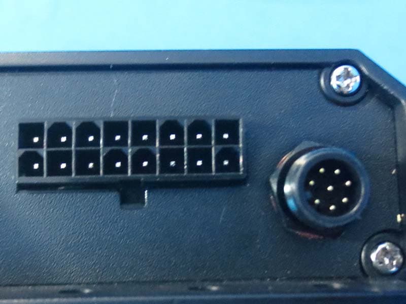
RGRPXIBT1002
Dec 13, 2015AMPLIFIED CONTROLLER FOR BLUETOOTH DEVICES
Equipment Class
DSS - Part 15 Spread Spectrum Transmitter