RGRPXIBT1002AMPLIFIED CONTROLLER FOR BLUETOOTH DEVICES
Stillwater Designs and Audio Inc.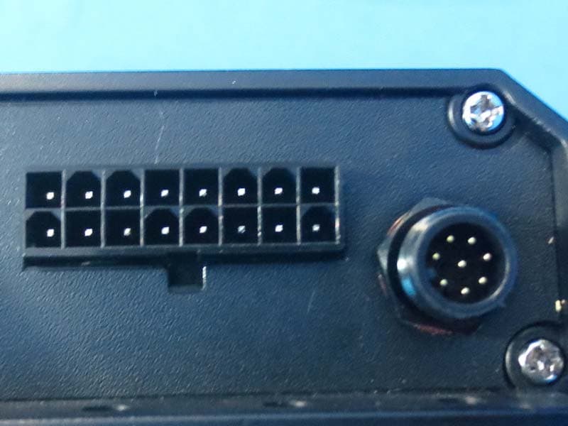
Click to zoom
Application Details
- Equipment Class
- DSS - Part 15 Spread Spectrum Transmitter
- Date of Grant
- Dec 13, 2015
- Application Purpose
- Original Equipment
- Date of Application
- Dec 13, 2015
- Equipment Note
- AMPLIFIED CONTROLLER FOR BLUETOOTH DEVICES
- Frequency Range
- 2402.00000000 - 2480.00000000
- Country
- United States
Documents & Files
Document Text
Text extracted from the exhibit documents filed with the FCC. Open a document above to read the original.
Users Manual
PXIBT100.2 AMPLIFIED CONTROLLER FOR BLUETOOTH ® DEVICES Owner’s Manual | English Manual del Propietario | Español AMPLIFICADOR DEL PXIBT Benutzerhandbuch | Deutsch VERSTÄRKER DER PXIBT Manuel d’utilisation | Française AMPLIFICATEUR DE PXIBT PXIBT STEREO INTEGRATED AMPLIFIER 2016 PXiBT100.2 Rev F.indd 12016 PXiBT100.2 Rev F.indd 110/15/2015 9:37:20 AM10/15/2015 9:37:20 AM 2 PXIBT100.2 OWNER’S MANUAL INSTALLATION Mounting: Choose a structurally sound location to mount your KICKER PXIBT100.2. Make sure there are no items behind the area where the screws will be driven. Choose a location that allows at least 4” (10cm) of open ventilation for the amplifi er. Drill four holes using a 7/64” (3mm) bit and use the supplied #8 screws to mount the amplifi er. Mount the unit behind the fairing, underneath the seat, or in another secure location isolated from weather. PERFORMANCE Authorized KICKER Dealer: Purchase Date: Serial Number: Model:PXIBT100.2 RMS output @ 4-ohms25 Watts x 2 RMS output @ 2-ohms50 Watts x 2 Selectable 12dB high-pass crossoverOFF, 60Hz, 80Hz, 120Hz Frequency response20Hz – 20kHz (+/- 1dB) RCA pre-out voltage2.5V RMS S/N ratio95dB Aux input sensitivity500mv – 1.75V USB audio input / charging5V/1A Length [in, cm]7, 17.8 Height [in, cm]1-5/8, 4 Width [in, cm]3-7/16, 8.7 Pro Tip: To get the best performance from your new KICKER Amplifi er and extend the warranty by 1 year, use genuine KICKER accessories and wiring. IMPORTANT SAFETY WARNING – PROLONGED CONTINUOUS OPERATION OF AN AMPLIFIER IN A DISTORTED OR CLIPPED MANNER CAN CAUSE YOUR AUDIO SYSTEM TO OVERHEAT, POSSIBLY CATCHING FIRE AND RESULTING IN SERIOUS DAMAGE TO YOUR COMPONENTS AND/OR VEHICLE. KICKER PRODUCTS ARE CAPABLE OF PRODUCING SOUND LEVELS THAT CAN PERMANENTLY DAMAGE YOUR HEARING! TURNING UP A SYSTEM TO A LEVEL THAT HAS AUDIBLE DISTORTION IS MORE DAMAGING TO YOUR EARS THAN LISTENING TO AN UNDISTORTED SYSTEM AT THE SAME VOLUME LEVEL. THE THRESHOLD OF PAIN IS ALWAYS AN INDICATOR THAT THE SOUND LEVEL IS TOO LOUD AND MAY PERMANENTLY DAMAGE YOUR HEARING. PLEASE USE COMMON SENSE WHEN CONTROLLING VOLUME. Mount the PXIBT100.2 using the included screws. 2016 PXiBT100.2 Rev F.indd 22016 PXiBT100.2 Rev F.indd 210/15/2015 9:37:30 AM10/15/2015 9:37:30 AM 3 The remote bar mounting clamp may be installed to either the left or right side on the back of the remote. Use the included remote mounting plate to perform a custom, fl ush installation of the remote. Be careful not to drill into wiring or vehicle mechanisms. You are solely responsible for safely and securely mounting the unit and remote. Use the cut-out template below to assist in the installation. Use the included remote extension cable if necessary Width: 86mm Height: 41mm Depth: 18mm 2016 PXiBT100.2 Rev F.indd 32016 PXiBT100.2 Rev F.indd 310/15/2015 9:37:30 AM10/15/2015 9:37:30 AM 4 Wiring: Disconnect the vehicle’s battery to avoid an electrical short. Connect the PXIBT harness to the amplifi er. A good ground connection is important. If this PXIBT100.2 is mounted in the front fairing of a motorcycle, it will be best to extend the ground wire all the way to the battery. Install a 15A fuse at the yellow +12V constant wire. Fuse installation should be within 18” (45cm) of the battery and in-line with the harness’ power cable, which is connected to your PXIBT100.2 unit. If you ever need to remove the amplifi er from the vehicle after it has been installed, the ground wire should be the last wire disconnected from the amplifi er--just the opposite as when you installed it. PXIBT100.2 unit USB Input and ChargingCrossover Switches Remote control input +12V Constant +12V Ignition Remote turn-on out Ground 3.5mm aux input To 2Ω or 4Ω speakers L - RCA Out L + R+ R- OPERATION 2016 PXiBT100.2 Rev F.indd 42016 PXiBT100.2 Rev F.indd 410/15/2015 9:37:30 AM10/15/2015 9:37:30 AM 5 Input Status LEDs: B/T - Slow Flash - Paired; no connection B/T - Rapid Flash - Pairing mode B/T - Solid - Bluetooth Connected Crossover Switches: Use the HI-PASS switches behind the protective rubber covering of the unit to set the internal crossover. Choose a cutoff of 60Hz, 80Hz, 120Hz, or OFF depending on the confi guration of switches 1 and 2. Never change the switches with the audio system on! Playing Music: The PXIBT100.2 is designed to receive audio via Bluetooth transfer protocol, 3.5mm auxiliary input, and USB input. The USB input supports MP3 and WMA fi le formats. The unit will power up in Bluetooth pairing mode when used for the fi rst time. To re-enter pairing mode at any time, press and hold the PLAY-PAUSE button until the Bluetooth LED fl ashes blue rapidly. To pair with an audio device, enter pairing mode on the unit, then enter ‘disovery mode’ on your audio device. Select ‘KICKER PXIBT’ on your audio device. The Bluetooth icon will be solid blue when connected and ready to play. If the Bluetooth icon fl ashes blue slowly, the unit is paired with a device, but not connected. Check your audio device if this occurs. Use short presses on the POWER button to cycle between Bluetooth, AUX, and USB input modes. The unit will remember the last input mode used when powered ON/OFF. You may press and hold the POWER button to turn the unit ON/OFF, however it is recommended that you install a switch in-line with the RED (+12V Ignition) power wire to mimic an accessory key switch. This will turn the unit ON/OFF with the vehicle. Changing Brightness: Press and hold the Track button for 5 seconds. After the remote blinks three times, the volume buttons will now control the remote LED brightness, from off (0) to full intensity (10). After the desired brightness is set and no key presses are detected for 5 seconds, the remote will blink three times and exit brightness mode. The volume buttons will now go back to controlling the volume level. POWER OFF/ON - Use if there is no switched ignition source in your vehicle. SELECT SOURCE - Bluetooth/AUX/USB Volume Brightness down Volume Brightness up Track Track B…
Text truncated - open the document above for the full version.
Cover Letter(s)
Stillwater Designs and Audio Inc. Declaration of Authorization We Name: Stillwater Designs and Audio Inc. Address: 3100 N Husband, Stillwater, Oklahoma, 74075, USA. Declare that: Name Representative of agent: Cathy Wang Agent Company name: BTL Inc. Address: No.3 Jinshagang 1 st Road, Shixia, Dalang Town City: Dong Guan Country: China is authorized to apply for Certification of the following product(s) and signing all the related documents including 731 forms: Product description: AMPLIFIED CONTROLLER FOR BLUETOOTH DEVICES Type designation: PXIBT100.2 Trademark: KICKER FCC ID: RGRPXIBT1002 on our behalf. Date: 2015-9-21 City: Stillwater Name: William Doering Function: Electronics Project Manager Signature:
Cover Letter(s)
Stillwater Designs and Audio Inc. Date: 2015-9-21 Federal Communications Commission Authorization and Evaluation Division Confidentiality Request regarding application for certification of FCC ID: RGRPXIBT1002 Pursuant to Sections 0.457 and 0.459 of the Commission’s Rules, we hereby request confidential treatment of information accompanying this application as outlined below: Block Diagram Schematics Operational Description The above materials contain trade secrets and proprietary information not customarily released to the public. The public disclosure of these materials may be harmful to the applicant and provide unjustified benefits to its competitors. The applicant understands that pursuant to Section 0.457 of the Rules, disclosure of this application and all accompanying documentation will not be made before the date of the Grant for this application. Sincerely, ----------------------------------- Grantee Contact’s Signature William Doering Printed name
Cover Letter(s)
To Whom it may Concern Please note that Mr. William Doering is authorized to represent Stillwater Designs and Audio Inc. and as such his signature should be acknowledged and accepted on documents pertaining to product testing and certifications. Thank you for your help and cooperation. Sincerely Joe Hobart R&D Electronics Manager Stillwater Designs and Audio Inc. [STILLWATER DESIGNS | Kicker] [3100 N Husband Stillwater, OK 74075 | P.O. Box 459 Stillwater, OK 74076 USA] [Ph: 405.624.8510 |
External Photos
Project No.: 1506C209 Page 2 of 10 Project No.: 1506C209 Page 3 of 10
ID Label/Location Info
Label location
Internal Photos
Project No.: 1506C209 Page 4 of 10 Project No.: 1506C209 Page 5 of 10 Project No.: 1506C209 Page 6 of 10 Project No.: 1506C209 Page 7 of 10 Project No.: 1506C209 Page 8 of 10 Project No.: 1506C209 Page 9 of 10 Project No.: 1506C209 Page 10 of 10
RF Exposure Info
FCC RF EXPOSURE REPORT FCC ID: RGRPXIBT1002 Project No. : 1506C209 Equipment : AMPLIFIED CONTROLLER FOR BLUETOOTH DEVICES Model : PXIBT100.2 Applicant : Stillwater Designs and Audio Inc Address : 3100 N Husband, Stillwater, OK, 74075, USA. According: : FCC Guidelines for Human Exposure IEEE C95.1 BTL INC. No.3, Jinshagang 1st Road, Shixia, Dalang Town, Dongguan, China. TEL: +86-769-8318-3000 FAX: +86-769-8319-6000 Table for Filed Antenna Ant. Brand Model NameAntenna TypeConnector Gain(dBi) 1 AMOTECH AMAN301512S T01 Chip N/A 3.29 GENERAL CONCULUSION: Maximum measured transmitter power: OutputPower (dBm) Output Power (mW) Limit (mW) 1.77 1.5 10 According to FCC KDB447498 V05, Appendix A, SAR Test Exclusion Thresholds for 100 MHz – 6 GHz and ≤ 50 mm The maximum measured output peak power of this EUT is 1.5mW, less than 10mW at 5mm distance. Conclusion: No SAR evaluation required since transmitter power is below FCC threshold
Test Report
Report No.: BTL-FICP-1-1506C209 Page 1 of 109 FCC&IC Radio Test Report FCC ID: RGRPXIBT1002 IC: 11078A-PXIBT1002 This report concerns (check one): Original Grant Class I Change Class II Change Project No. : 1506C209 Equipment : AMPLIFIED CONTROLLER FOR BLUETOOTH DEVICES Model Name : PXIBT100.2 Applicant : Stillwater Designs and Audio Inc Address : 3100 N Husband, Stillwater, OK, 74075, USA. Date of Receipt : Jun. 23, 2015 Date of Test : Jun. 23, 2015 ~ Aug. 27, 2015 Issued Date : Aug. 31, 2015 Tested by : BTL Inc. Testing Engineer : (Shawn Xiao) Technical Manager : (David Mao) Authorized Signatory : (Steven Lu) BTL INC. No.3, Jinshagang 1st Road, Shixia, Dalang Town, Dongguan, Guangdong, China. TEL: +86-769-8318-3000 FAX: +86-769-8319-6000 Report No.: BTL-FICP-1-1506C209 Page 2 of 109 Declaration BTL represents to the client that testing is done in accordance with standard procedures as applicable and that test instruments used has been calibrated with the standards traceable to National Measurement Laboratory (NML) of CHINA, or National Institute of Standards and Technology (NIST) of U.S.A. BTL's reports apply only to the specific samples tested under conditions. It is manufacture’s responsibility to ensure that additional production units of this model are manufactured with the identical electrical and mechanical components. BTL shall have no liability for any declarations, inferences or generalizations drawn by the client or others from BTL issued reports. BTL’s report must not be used by the client to claim product certification, approval, or endorsement b y NVLAP, NIST, or any agency of the Federal Government. This report is the confidential property of the client. As a mutual protection to the clients, the public and BTL-self, extracts from the test report shall not be reproduced except in full with BTL’s authorized written approval. BTL’s laboratory quality assurance procedures are in compliance with the ISO Guide 17025 requirements, and accredited by the conformity assessment authorities listed in this test report. Limitation For the use of the authority's logo is limited unless the Test Standard(s)/Scope(s)/Item(s) mentioned in this test report is (are) included in the conformity assessment authorities acceptance respective. Report No.: BTL-FICP-1-1506C209 Page 3 of 109 Table of Contents Page 1 . CERTIFICATION 7 2 . SUMMARY OF TEST RESULTS 8 2.1 TEST FACILITY 9 2.2 MEASUREMENT UNCERTAINTY 9 3 . GENERAL INFORMATION 10 3.1 GENERAL DESCRIPTION OF EUT 10 3.2 DESCRIPTION OF TEST MODES 12 3.3 TABLE OF PARAMETERS OF TEXT SOFTWARE SETTING 12 3.4 BLOCK DIAGRAM SHOWING THE CONFIGURATION OF SYSTEM TESTED 13 3.5 DESCRIPTION OF SUPPORT UNITS 13 4 . EMC EMISSION TEST 14 4.1 CONDUCTED EMISSION MEASUREMENT 14 4.1.1 POWER LINE CONDUCTED EMISSION LIMITS 14 4.1.2 TEST PROCEDURE 14 4.1.3 DEVIATION FROM TEST STANDARD 14 4.1.4 TEST SETUP 15 4.1.5 EUT OPERATING CONDITIONS 15 4.1.6 EUT TEST CONDITIONS 15 4.1.7 TEST RESULTS 15 4.2 RADIATED EMISSION MEASUREMENT 16 4.2.1 RADIATED EMISSION LIMITS 16 4.2.2 TEST PROCEDURE 20 4.2.3 DEVIATION FROM TEST STANDARD 20 4.2.4 TEST SETUP 21 4.2.5 EUT OPERATING CONDITIONS 22 4.2.6 EUT TEST CONDITIONS 22 4.2.7 TEST RESULTS (9KHZ TO 30MHZ) 22 4.2.8 TEST RESULTS (30MHZ TO 1000 MHZ) 23 4.2.9 TEST RESULTS (ABOVE 1000 MHZ) 23 5 . NUMBER OF HOPPING CHANNEL 24 5.1 APPLIED PROCEDURES 24 5.1.1 TEST PROCEDURE 24 5.1.2 DEVIATION FROM STANDARD 24 5.1.3 TEST SETUP 24 5.1.4 EUT OPERATION CONDITIONS 24 5.1.5 EUT TEST CONDITIONS 24 5.1.6 TEST RESULTS 24 6 . AVERAGE TIME OF OCCUPANCY 25 Report No.: BTL-FICP-1-1506C209 Page 4 of 109 Table of Contents Page 6.1 APPLIED PROCEDURES / LIMIT 25 6.1.1 TEST PROCEDURE 25 6.1.2 DEVIATION FROM STANDARD 25 6.1.3 TEST SETUP 25 6.1.4 EUT OPERATION CONDITIONS 26 6.1.5 EUT TEST CONDITIONS 26 6.1.6 TEST RESULTS 26 7 . HOPPING CHANNEL SEPARATION MEASUREMENT 27 7.1 APPLIED PROCEDURES / LIMIT 27 7.1.1 TEST PROCEDURE 27 7.1.2 DEVIATION FROM STANDARD 27 7.1.3 TEST SETUP 27 7.1.4 EUT TEST CONDITIONS 27 7.1.5 TEST RESULTS 27 8 . BANDWIDTH TEST 28 8.1 APPLIED PROCEDURES 28 8.1.1 TEST PROCEDURE 28 8.1.2 DEVIATION FROM STANDARD 28 8.1.3 TEST SETUP 28 8.1.4 EUT OPERATION CONDITIONS 28 8.1.5 EUT TEST CONDITIONS 28 8.1.6 TEST RESULTS 28 9 . PEAK OUTPUT POWER TEST 29 9.1 APPLIED PROCEDURES / LIMIT 29 9.1.1 TEST PROCEDURE 29 9.1.2 DEVIATION FROM STANDARD 29 9.1.3 TEST SETUP 29 9.1.4 EUT OPERATION CONDITIONS 29 9.1.5 EUT TEST CONDITIONS 29 9.1.6 TEST RESULTS 29 10 . ANTENNA CONDUCTED SPURIOUS EMISSION 30 10.1 APPLIED PROCEDURES / LIMIT 30 10.1.1 TEST PROCEDURE 30 10.1.2 DEVIATION FROM STANDARD 30 10.1.3 TEST SETUP 30 10.1.4 EUT OPERATION CONDITIONS 30 10.1.5 EUT TEST CONDITIONS 30 10.1.6 TEST RESULTS 30 11 . MEASUREMENT INSTRUMENTS LIST 31 12 . EUT TEST PHOTO 33 ATTACHMENT A - CONDUCTED EMISSION 36 Report No.: BTL-FICP-1-1506C209 Page 5 of 109 Table of Contents Page ATTACHMENT B - RADIATED EMISSION (9KHZ-30MHZ) 37 ATTACHMENT C - RADIATED EMISSION (30MHZ TO 1000MHZ) 39 ATTACHMENT D - RADIATED EMISSION (ABOVE 1000MHZ) 46 ATTACHMENT E - NUMBER OF HOPPING CHANNEL 71 ATTACHMENT F - AVERAGE TIME OF OCCUPANCY 73 ATTACHMENT G - HOPPING CHANNEL SEPARATION MEASUREMENT 86 ATTACHMENT H - BANDWIDTH 91 ATTACHMENT I - PEAK OUTPUT POWER 96 ATTACHMENT J - ANTENNA CONDUCTED SPURIOUS EMISSION 101 Report No.: BTL-FICP-1-1506C209 Page 6 of 109 REPORT ISSUED HISTORY Issued No. Description Issued Date BTL-FICP-1-1506C209 Original Issue. Aug. 31, 2015 Report No.: BTL-FICP-1-1506C209 Page 7 of 109 1. CERTIFICATION Equipment : AMPLIFIED CONTROLLER FOR BLUETOOTH DEVICES Brand Name : KICKER Model Name : PXIBT100.2 Applicant : Stillwater Designs and Audio Inc Manufacturer : Hangzhou Newsources Electronics Co., Ltd Address : No.7 Houyang Rd, Anxi Industrial Zone, Liangzhu, Hangzhou Factory : Hangzhou Newsources Electronics Co., Ltd Address : No.7 Houyang Rd, Anxi Industrial Zone, Liangzhu, Hangzhou Date of Test : Jun. 23, 2015 ~ Aug. 27, 2015 Test Sample : Engineering Sample Standard(s) : FCC Part1…
Text truncated - open the document above for the full version.
Test Setup Photos
Report No.: BTL-FICP-1-1506C209 Page 33 of 109 12. EUT TEST PHOTO Radiated Measurement Photos 9KHz to 30MHz Report No.: BTL-FICP-1-1506C209 Page 34 of 109 Radiated Measurement Photos 30MHz to 1000MHz Report No.: BTL-FICP-1-1506C209 Page 35 of 109 Radiated Measurement Photos Above 1000MHz
Contact Information
Applicant
Joe Hobart(R&D Electronics Manager)
Test Firm
BTL Inc.Daisy Dai
Technical Specifications
| # | Rule Parts | Frequency Range | Power Output |
|---|---|---|---|
| 1 | 15C | 2.40 GHz - 2.48 GHz | 1.50 mW |
Other Applications from Stillwater Designs and Audio Inc.

RGR-48BTCAN65
Aug 23, 2023Powered BT Cans
Equipment Class
DSS - Part 15 Spread Spectrum Transmitter
RGR-KPBRC
Jul 18, 2021Powerbar Remote
Equipment Class
DXX - Part 15 Low Power Communication Device Transmitter
RGR-47KPB
Jun 30, 2021Powerbar
Equipment Class
DSS - Part 15 Spread Spectrum Transmitter
RGR-46KMC2
Mar 26, 2020Marine Audio
Equipment Class
DSS - Part 15 Spread Spectrum Transmitter
RGR-HP401402BT
Jul 06, 2014Bluetooth headphone
Equipment Class
DXT - Part 15 Low Power Transceiver, Rx Verified