RIW-ZWX-B290802.11b USB WLAN Pen Adapter
Zinwell Corporation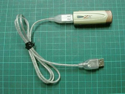
Click to zoom
Application Details
- Equipment Class
- DTS - Digital Transmission System
- Date of Grant
- Nov 19, 2003
- Application Purpose
- Original Equipment
- Date of Application
- Nov 19, 2003
- Equipment Note
- 802.11b USB WLAN Pen Adapter
- Frequency Range
- 2412.00000000 - 2462.00000000
- Company
- Zinwell Corporation
- Country
- Taiwan
Documents & Files
Document Text
Text extracted from the exhibit documents filed with the FCC. Open a document above to read the original.
Users Manual
Wireless LAN Device Series WLAN USB Pen-Type Adapter ZPlus-B290 User’s Manual Version. 1.02 (10.07.2003) 1 Notice “ This device complies with Part 15 of the FCC Rules. Operation is subject to the following two conditions: (1) this device may not cause harmful interference, and (2) this device must accept any interference received, including interference that may cause undesired operation. Warning: Changes or modifications to this unit not expressly approved by the party responsible for compliance could void the user authority to operate the equipment. This device complies with Part 15 of the FCC Rules. Operation is subject to the following two conditions: (1) this device may not cause harmful interference, and (2) this device must accept any interference received, including interference that may cause undesired operation. The users manual or instruction manual for an intentional or unintentional radiator shall caution the user that changes or modifications not expressly approved by the party responsible for compliance could void the user’s authority to operate the equipment. NOTE: This equipment has been tested and found to comply with the limits for a Class B digital device, pursuant to Part 15 of the FCC Rules. These limits are designed to provide reasonable protection against harmful interference in a residential installation. This equipment generates, uses and can radiate radio frequency energy and, if not installed and used in accordance with the instructions, may cause harmful interference to radio communications. However, there is no guarantee that interference will not occur in a particular installation. If this equipment does cause harmful interference to radio or television reception, which can be determined by turning the equipment off and on, the user is encouraged to try to correct the interference by one or more of the following measures: Reorient or relocate the receiving antenna. Increase the separation between the equipment and receiver. Connect the equipment into an outlet on a circuit different from that to which the receiver is needed. Consult the dealer or an experienced radio/TV technician for help. The Product name has been tested to the FCC exposure requirements (Specific Absorption Rate). CAUTION: 1. The equipment complies with FCC RF radiation exposure limits set forth for an uncontrolled environment, under 47 CFR 2.1093 paragraph (d)(2). 2. This Transmitter must not be co-located or operating in conjunction with any other antenna or transmitter. 2 Contents 1 Introduction....................................................................................... 3 1.1 Package Contents ........................................................................................................ 3 1.2 System Requirements.................................................................................................. 3 2 Quick Installation.............................................................................. 4 3 Installation Procedures Under MS Windows.................................. 5 3.1 Installing the Application and Drivers under Windows 98SE/Me /2000/XP......... 5 3.2 Uninstall the Driver/Application.............................................................................. 12 4 Configuration & Monitor Utility ..................................................... 15 4.1 Quick step-by-step start to connect site................................................................... 15 4.2 System tray................................................................................................................. 18 4.3 Main dialog box of Utility ......................................................................................... 18 4.4 More Setting.............................................................................................................. 19 4.5 General connection setting ....................................................................................... 20 4.6 Encryption.................................................................................................................. 21 4.7 Language .................................................................................................................... 22 4.8 Profile .........................................................................................................................22 4.9 Other...........................................................................................................................23 3 1 1 I I n n t t r r o o d d u u c c t t i i o o n n This USB device is a Wireless LAN Adapter with a rate of 1, 2, 5.5, and 11 Mbps operating in the ISM band using Direct Sequence Spread Spectrum (DSSS) transmission, conforming the IEEE 802.11b standard. For these card currently provides Device Drivers for Microsoft Windows ® 98SE/Me/2000/XP. 1.1 Package Contents Before you do anything, open your package and verify it includes: z ZPlus-B290 Adapter z USB Cable z Setup Utility CD containing User’s Manual z Quick Start Guide 1.2 System Requirements z Operating System: MS Windows 98SE/Me/2000/XP. z Desktop/notebook PC with CD-ROM drive and USB interface. 4 2 2 Q Q u u i i c c k k I I n n s s t t a a l l l l a a t t i i o o n n This section provides a quick step by step guide on how to install your Wireless LAN USB Adapter. Please follow the steps described below and refer to the appropriate sections for further details: z Power on the computer. z Please make sure that you don’t insert your WLAN USB adapter yet. z Install the drivers and application: 1. Insert the given Installation CD into your CD-ROM drive. 2. Click “Install/Uninstall software” button to install. 3. Follow the installation instructions from the InstallShield Wizard by pressing the “Next” button. 4. Choose the appropriate of installation, according to your needs (Application, Drivers) 5. If you want to set the path of your choice, select “Browse” and then “Next”. 6. Then setup wizard w…
Text truncated - open the document above for the full version.
External Photos
Photo 1: Exterior photo XPlus-B290 Photo 2: Exterior photo XPlus-B290 Photo 3: Exterior photo XPlus-B290
ID Label/Location Info
FCC ID Label Location
RF Exposure Info
0597 ILAC MRA Specific Absorption Rate (SAR) Test Report for ZINWELL CORPORATION on the PALM Size Model Number: ZPlus-B290 Test Report: EME-031213 Date of Report: Nov. 10, 2003 Date of test: Oct. 29, 2003 Total No of Pages Contained in this Report: 68 Accredited for testing to FCC Part 15 Tested by: Clay Chen Reviewed by: Elton Chen Review Date: Nov. 10, 2003 All services undertaken are subject to the following general policy: Reports are submitted for exclusive use of the client to whom they are addressed. Their significance is subject to the adequacy and representative character of the samples and to the comprehensiveness of the tests, examinations or surveys made. This report shall not be reproduced except in full, without written consent of Intertek Testing Services, Taiwan Ltd. FCC ID. : RIW-ZWX-B290 Report No.: EME-031213 Page 2 of 68 Table of Contents 1.0 Job Description...........................................................................................................4 1.1 Client Information...................................................................................................4 1.2 Equipment under test (EUT)...................................................................................4 1.3 Test plan reference..................................................................................................5 1.4 System test configuration........................................................................................5 1.4.1 System block diagram & Support equipment......................................................5 1.4.2 Test Position.........................................................................................................6 1.4.3 Test Condition......................................................................................................6 1.5 Modifications required for compliance...................................................................7 1.6 Additions, deviations and exclusions from standards.............................................7 2.0 SAR Evaluation..........................................................................................................8 2.1 SAR Limits.............................................................................................................8 2.2 Configuration Photographs.....................................................................................9 2.3 SAR measurement system....................................................................................13 2.4 SAR measurement system validation...................................................................14 2.5 Test Result.............................................................................................................15 3.0 Test Equipment.........................................................................................................17 3.1 Equipment List......................................................................................................17 3.2 Body Tissue Simulating Liquid for evaluation test...............................................18 3.3 Head Tissue Simulating Liquid for System performance Check test...................18 3.4 E-Field Probe and 2450 Balanced Dipole Antenna Calibration...........................18 3.5 Measurement Uncertainty.....................................................................................19 3.6 Measurement Traceability.....................................................................................22 4.0 WARNING LABEL INFORMATION - USA..........................................................23 5.0 REFERENCES.........................................................................................................24 6.0 DOCUMENT HISTORY..........................................................................................25 APPENDIX A - SAR Evaluation Data...........................................................................26 APPENDIX B – 2450MHz body liquid Calibration Data..............................................35 Photographs.....................................................................................................................37 APPENDIX C - E-Field Probe and 2450MHz Balanced Dipole Antenna.....................42 Calibration Data..............................................................................................................42 FCC ID. : RIW-ZWX-B290 Report No.: EME-031213 Page 3 of 68 STATEMENT OF COMPLIANCE The ZINWELL sample device, model # ZPlus-B290 was evaluated in accordance with the requirements for compliance testing defined in FCC OET Bulletin 65, Supplement C (Edition 01-01). Testing was performed at the Intertek Testing Services facility in Hsinchu, Taiwan. For the evaluation, the dosimetric assessment system INDEXSAR SARA2 was used. The phantom employed was the box phantom of 2mm thick in one wall. The total uncertainty for the evaluation of the spatial peak SAR values averaged over a cube of 1g tissue mass had been assessed for this system to be ±29.7%. The device was tested at their maximum output power declared by the ZINWELL. In summary, the maximum spatial peak SAR value for the sample device averaged over 1g was found to be: Phantom Position SAR 1g , mW/g 2mm thick box phantom wall EUT bottom to the phantom 0.025 mW/g. In conclusion, the tested Sample device was found to be in compliance with the requirements defined in OET Bulletin 65, Supplement C (Edition 01-01) for body configurations. FCC ID. : RIW-ZWX-B290 Report No.: EME-031213 Page 4 of 68 1.0 Job Description 1.1 Client Information The ZPlus-B290 has been tested at the request of: Company: ZINWELL CORPORATION No. 2 Wen-Hua Road, Hsinchu Industrial Park, Hsinchu Hsien 303, Taiwan 1.2 Equipment under test (EUT) Product Descriptions: Equipment PALM Size Trade Name ZINWELL Model No: ZPlus-B290 FCC ID RIW-ZWX-B290 S/N No. Not Labeled Category Portable RF Exposure Uncontrolled Environment Frequency Band 2412 – 2462 MHz S…
Text truncated - open the document above for the full version.
Test Report
FCC ID. : RIW-ZWX-B290 Report No.: EME-031043 Page 1 of 34 EMC TEST REPORT Report No. : EME-031043 Model No. : ZPlus-B290 Issued Date : Oct. 2, 2003 Applicant : ZINWELL CORPORATION No. 2 Wen-Hua Road, Hsinchu Industrial Park, Hsinchu Hsien 303, Taiwan Test By : Intertek Testing Services Taiwan Ltd. No. 11, Lane 275, Ko-Nan 1 Street, Chia-Tung Li, Shiang-Shan District, Hsinchu City, Taiwan This test report consists of 34 pages in total. It may be duplicated completely for legal use with the allowance of the applicant. It shall not be reproduced except in full, without the written approval of Intertek Laboratory. The test result in this report only applies to the tested sample. Jerry Liu Project Engineer Reviewed By Elton Chen FCC ID. : RIW-ZWX-B290 Report No.: EME-031043 Page 2 of 34 Table of Contents Summary of Tests..........................................................................................................3 1. General information..................................................................................................4 1.1 Identification of the EUT....................................................................................4 1.2 Additional information about the EUT................................................................4 1.3 Antenna description............................................................................................5 1.4 Peripherals equipment.........................................................................................5 2. Test specifications.....................................................................................................6 2.1 Test standard.......................................................................................................6 2.2 Operation mode..................................................................................................6 2.3 Test equipment....................................................................................................7 3. Minimum 6dB Bandwidth test...................................................................................8 3.1 Operating environment.......................................................................................8 3.2 Test setup & procedure........................................................................................8 3.3 Measured data of Minimum 6dB Bandwidth test results......................................8 4. Maximum Output Power test...................................................................................12 4.1 Operating environment.....................................................................................12 4.2 Test setup & procedure......................................................................................12 4.3 Measured data of Maximum Output Power test results......................................12 5. Radiated Emission test............................................................................................13 5.1 Operating environment.....................................................................................13 5.2 Test setup & procedure......................................................................................13 5.3 Emission limits.................................................................................................14 5.4 Radiated spurious emission test data.................................................................15 5.4.1 Measurement results: frequencies equal to or less than 1 GHz........................15 5.4.2 Measurement results: frequency above 1GHz.................................................16 6. Power Spectrum Density test...................................................................................19 6.1 Operating environment.....................................................................................19 6.2 Test setup & procedure......................................................................................19 6.3 Measured data of Power Spectrum Density test results......................................19 7. Emission on the band edge §FCC 15.247(C)...........................................................23 7.1 Band-edge (Conducted method)........................................................................24 7.2 Band-edge (Radiated method)...........................................................................26 8. Power Line Conducted Emission test §FCC 15.207.................................................30 8.1 Operating environment.....................................................................................30 8.2 Test setup & procedure......................................................................................30 8.3 Power Line Conducted Emission test data.........................................................32 FCC ID. : RIW-ZWX-B290 Report No.: EME-031043 Page 3 of 34 Summary of Tests Wireless USB Pen-Type Adapter-Model: ZPlus-B290 FCC ID: RIW-ZWX-B290 Test Reference Results Minimum 6dB Bandwidth test 15.247(a)(2) Complies Maximum Output Power test 15.247(b) Complies Radiated Spurious Emission test 15.205, 15.209 Complies Power Spectrum Density test 15.247(d) Complies Power Line Conducted Emission test 15.207 Complies FCC ID. : RIW-ZWX-B290 Report No.: EME-031043 Page 4 of 34 1. General information 1.1 Identification of the EUT Applicant : ZINWELL CORPORATION Product : Wireless USB Pen-Type Adapter Model No. : ZPlus-B290 FCC ID. : RIW-ZWX-B290 Frequency Range : 2412MHz to 2462MHz Channel Number : 11 Frequency of Each Channel : 2412MHz, 2417MHz, 2422MHz, 2427MHz, 2432MHz, 2437MHz, 2442MHz, 2447MHz, 2452MHz, 2457MHz, 2462MHz Type of Modulation : CCK (11Mps, 5.5Mbps), DQPSK (2Mbps), DBPSK (1Mbps) Rated Power : 5Vdc Power Cord : N/A Sample Received : Sep. 9, 2003 Test Date(s) : Sep. 9, 2003 to Sep. 16, 2003 A FCC DoC report has been generated for the client. 1.2 Additional information about the EUT This USB device is a Wireless LAN Adapter with a rate of 1, …
Text truncated - open the document above for the full version.
Test Setup Photos
Photo 1: Conducted Test set-up Photo 2: Conducted Test set-up Photo 3: Conducted Test set-up
Test Setup Photos
Photo 1: Spurious Test set-up photo Photo 2: Spurious Test set-up photo
Contact Information
Applicant
Jeff Huang(Engineer)
Technical Contact
Intertek Testing Services Taiwan, Ltd.Elton Chen
[email protected]+886 3 519 1411
No. 11, Lane 275, Ko-Nam 1St. Chia-Tung Li · Hsinchu City · Taiwan
Test Firm
Intertek Testing Services Taiwan Ltd.Alpha Liu
Technical Specifications
| # | Rule Parts | Frequency Range | Power Output |
|---|---|---|---|
| 1 | 15C | 2.41 GHz - 2.46 GHz | 37.00 mW |
Other Applications from Zinwell Corporation
RIWZAT600B
Sep 19, 2023ATSC 3.0 STB
Equipment Class
NII - Unlicensed National Information Infrastructure TX
RIWZAT6000
Sep 17, 2023ATSC 3.0 STB
Equipment Class
NII - Unlicensed National Information Infrastructure TX
RIW-ZWA-G220
Aug 05, 2007ZINWELL 802.11b/g Wireless AP
Equipment Class
DTS - Digital Transmission System
RIW-ZW-2200
Dec 20, 2006802.11 a/g WLAN Outdoor AP
Equipment Class
DTS - Digital Transmission System
RIW-ZW-2000-22
Sep 06, 20062.4G OutDoor Device
Equipment Class
DTS - Digital Transmission System