RKVAB450KLow Power FM Transceiver
Aerielle, Inc
Click to zoom
Application Details
- Equipment Class
- DXX - Part 15 Low Power Communication Device Transmitter
- Date of Grant
- Feb 01, 2006
- Application Purpose
- Original Equipment
- Date of Application
- Feb 01, 2006
- Equipment Note
- Low Power FM Transceiver
- Frequency Range
- 88.10000000 - 107.90000000
- Company
- Aerielle, Inc
- Country
- United States
Documents & Files
Document Text
Text extracted from the exhibit documents filed with the FCC. Open a document above to read the original.
Users Manual
Congratulations! Your new Kensington Digital FM Radio & Transmitter for iPod (Kensington FM/TR) offers you the freedom to listen to music the way that you want. With the Kensington FM/TR plugged into your iPod, you may transmit music from your iPod to any FM stereo (car, home, etc.) or listen to any local FM radio broadcasts. Please read this short manual to learn valuable information about the proper use and installation of your new Kensington FM/TR. Register your Kensington FM/TR online athttp://www.kensington.com/register. Some Important Things to Remember •To ensure compatibility, please be sure that your iPod device software is up to date (note: this is not your iTunes software, butApple’s iPod Updater). You can download the latest iPod Updater software from Apple’s website at: www.apple.com/ipod/download. •If you wish to listen to your iPod, plug your headphones directly into the iPod headphone jack. •To turn off the Kensington FM/TR, press and hold the Mode button (C) until the display shows OFF. •Pressing the Mode button (C) will allow you to cycle between FM Transmitter and FM Receiver modes. To Play Your iPod Tunes Through an FM Radio 1. Plug in the Kensington FM/TR to your iPod. (Be sure your iPod is properly charged since this device draws power directly from your iPod.) 2. If your iPod is not yet powered on, press play to turn it on. 3. For maximum performance, find a clearstation (with pure static) on your car or home stereo. Pure orclearmeans no music, no talking, just static. 4. Next, adjust the Kensington FM/TR to match the station frequency as indicated on your stereo. (Holding onto the tune (D or E) button will result in faster tuning.) 5. Select a desired song. 6. Press play on your iPod to begin transmitting music through your stereo. (To adjust volume, you will need to adjust the volume setting of your stereo.) Note: Your Kensington Digital FM/TR LCD screen will blink as it tries to lock into the FM frequency for the highest quality audio. During this time, you may not hear your music. Tips Transmitter Pre-sets: To program a station into the presets (H), tune to the desired station, press and hold any 1 of the 4 station presets for approximately 2 seconds. Clear Station Seek: 1. Plug in a set of headphones into the Kensington FM/TR (I). (This step is necessary because the headphones act as an antenna to find the next clear station.) 2. Press and hold either the volume up (F) or volume down (G) button for at least a second to begin the clear station seek. The LCD will display the next clear station. (Pressing volume up or down will result in the clear station seek to scan up or down respectively. The backlight will begin to flash indicating that the clear station is now set to transmit.) 3. Tune your FM stereo to match the same station as displayed on the Kensington FM/TR. To Listen to FM Radio 1. Plug in the Kensington FM/TR to your iPod. (Be sure your iPod is properly charged since this device draws power directly from your iPod.) 2. Plug in a set of headphones into the Kensington FM/TR (I). 3. Press the “Mode” button (C) to switch to ‘r E C’ mode to activate the FM receiver mode. 4. Using the tuning buttons (D or E), tune to any FM station. 5. To adjust the volume, use the volume control buttons (F or G). (Using the iPod volume control will not work.) Note: While you are listening to the FM Radio, you may notice your iPod screen volume adjusting periodically in order to maintain the flow of power to the FM Radio. This does not affect the volume of the radio. If you have the Screen Backlight option turned on, this will result in your backlight turning on periodically and is normal. If desired, you can turn off the backlight option to prevent this. Tips Radio Pre-sets: To program a station into the presets (H), tune to the desired station, press and hold any 1 of the 4 station presets for approximately 2 seconds. Technical Support Technical support is available to all registered users of Kensington products. There is no charge for technical support except the cost of the phone call, and long distance charges where applicable. Technical Support Contact information can be found on the last page of this manual. Technical Support Tips •You may find the answer to your problem in the Frequently Asked Questions (FAQ) section of the Support area on the Kensington Website: www.kensington.com. •Call from a phone where you have access to your your notebook, or other digital device •Be prepared to provide the following information: -Name, address, and telephone number -The name of the Kensington product -Make and model of your your notebook, or other digital device -Your system software and version (where applicable) -Symptoms of the problem and what led to them 1-Year Limited Warranty KENSINGTON TECHNOLOGY GROUP ("KENSINGTON") warrants the PRODUCT against defects in material and workmanship under normal use and service for one year from the original date of purchase. KENSINGTON, atits option, shall repair or replace the defective unit covered by this warranty. Please retain the dated sales receipt as evidence of the date of purchase. You will need it for any warranty service. In order to keep this warranty in effect, the product must have been handled and used as prescribed in the instructions accompa- nying this warranty. This warranty does not cover any damage due to accident, misuse, abuse, or negligence. DISCLAIMER OF WARRANTY The limited warranty described herein is your sole remedy. To the extent permitted by law, Kensington disclaims all other implied or express warranties including all warranties of merchantability and/or fitness for a particular purpose. LIMITATION OF LIABILITY Except to the extent of repairing or replacing the power inverter as expressly stated in the limited warranty described herein, Kensington shall not be liable for any damages, whether direct, indirect, incidental, special, consequential, exemplary, or otherwise, including lost revenues, lost pr…
Text truncated - open the document above for the full version.
Cover Letter(s)
Aerielle, Inc. 625 Ellis Street, Suite 206 Mountain View, CA 94043 www.aerielle.com Tel: 650.967.4047 Fax: 413.581.6020 Federal Communications Commission Authorization and Evaluation Division 7435 Oakland Mills Rd. Columbia, MD 21046 Fax: (310) 344-2050 Reference FCC ID: RKVAB450K Organization: Aerielle Inc. Request under 47 CFR 0.457 and 0.459 that materials submitted to the commission be withheld from public inspection. Aerielle, Inc. hereby requests that the materials attached here to be withheld from public inspection in accordance with 47 CFR 47 0.457 and 0.459. Specifically, Aerielle Inc. requests that the following materials be withheld from public inspection under 47 CFR 0.457 and 0.459 because the schematics and designs are considered confidential trade secrets and technical data which customarily would be guarded from competitors: (1) Detailed circuit schematics are found in the FCC electronic attachments. (2) Detailed component lists (bill of materials) are found in the FCC electronic attachments. (3) Block Diagram found in the FCC electronic attachments (4) Operational Description (Theory of Operation) found in the FCC electronic attachments. (5) Product specification found in the FCC electronic attachments. Therefore, in accordance with CFR 47 0.457 and 0.459, Aerielle, Inc. requests that the above listed materials, copies of which are here, to be withheld from public inspection. Authorized Signature: Date: January 16, 2006 Alan D. Czeszynski Director, Product & Operations Management Aerielle Inc. 625 Ellis St. Ste 206 Mountain View, CA 94043 650-967-4047
External Photos
Aerielle, Inc. FCC ID: RKVAB450K EXHIBIT C - EUT PHOTOGRAPHS EUT – Front View EUT – Back View
ID Label/Location Info
EXHIBIT A - FCC ID LABEL INFORMATION Proposed FCC ID Label Proposed Label Location on EUT Bottom View of EUT/FCC ID Label FCC ID: RKVAB450K This device complies with Part 15 of the FCC Rules. Operation is subject to the following two conditions: (1) this device may not cause harmful interference, and (2) this device must accept any interference received, including interference that may cause undesired operation.
Internal Photos
Aerielle, Inc. FCC ID: RKVAB450K EUT – Cover off View EUT – Main Board View (1) Aerielle, Inc. FCC ID: RKVAB450K EUT – Main Board View (2)
Test Report
Note: The test report is specially limited to the above company and this particular sample only. It may not be duplicated without prior written consent of Bay Area Compliance Laboratory Corporation. This report must not be used by the client to claim product certification, approval, or endorsement by NVLAP, NIST or any agency of the US Government. FCC PART 15.239 EMI MEASUREMENT AND TEST REPORT For Aerielle, Inc. 625 Ellis Street, Suite 206 Mountain View, CA 94043 FCC ID: RKVAB450K This Report Concerns: Original Report Equipment Type: Low Power FM Transceiver Test Engineer: Snell Leong Report No.: R0512202 Report Date: 2006-1-19 Reviewed By: James Ma Prepared By: Bay Area Compliance Laboratory Corporation (BACL) 230 Commercial Street Sunnyvale, CA 94085 Tel: (408) 732-9162 Fax: (408) 732 9164 Aerielle, Inc. FCC ID: RKVAB450K Report # R0512202Rpt.doc Page 2 of 17 FCC Part 15.239 Test Report TABLE OF CONTENTS GENERAL INFORMATION.......................................................................................................................................3 PRODUCT DESCRIPTION FOR EQUIPMENT UNDER TEST (EUT) ....................................................................................3 OBJECTIVE...................................................................................................................................................................3 RELATED SUBMITTAL(S)/GRANT(S).............................................................................................................................3 TEST METHODOLOGY..................................................................................................................................................3 TEST FACILITY.............................................................................................................................................................3 SYSTEM TEST CONFIGURATION ..........................................................................................................................4 JUSTIFICATION.............................................................................................................................................................4 EUT EXERCISE SOFTWARE..........................................................................................................................................4 SPECIAL ACCESSORIES.................................................................................................................................................4 SCHEMATICS / BLOCK DIAGRAM..................................................................................................................................4 EQUIPMENT MODIFICATIONS.......................................................................................................................................4 LOCAL SUPPORT EQUIPMENT LIST AND DETAILS........................................................................................................4 INTERFACE PORTS AND CABLING.................................................................................................................................4 CONFIGURATION OF TEST SYSTEM..............................................................................................................................5 TEST SETUP BLOCK DIAGRAM.....................................................................................................................................5 SUMMARY OF TEST RESULTS ...............................................................................................................................6 §15.203 - ANTENNA REQUIREMENT......................................................................................................................7 STANDARD APPLICABLE..............................................................................................................................................7 §15.205 & §15.209 - SPURIOUS RADIATED EMISSION........................................................................................8 MEASUREMENT UNCERTAINTY....................................................................................................................................8 EUT SETUP..................................................................................................................................................................9 RECEIVER SETUP..........................................................................................................................................................9 TEST EQUIPMENT LIST AND DETAILS...........................................................................................................................9 TEST PROCEDURE......................................................................................................................................................10 CORRECTED AMPLITUDE & MARGIN CALCULATION.................................................................................................10 ENVIRONMENTAL CONDITIONS..................................................................................................................................10 SUMMARY OF TEST RESULTS.....................................................................................................................................10 SPURIOUS EMISSION 30MHZ-1080MHZ @ 3 METER................................................................................................11 §15.239 (A) – FREQUENCY RANGE & OCCUPIED BANDWITH .....................................................................12 MEASUREMENT UNCERTAINTY..................................................................................................................................12 TEST PROCEDURE......................................................................................................................................................12 TEST EQUIPMENT LIST AND DETAILS......................................…
Text truncated - open the document above for the full version.
Test Setup Photos
Aerielle, Inc. FCC ID: RKVAB450K EXHIBIT B - TEST SETUP PHOTOGRAPHS Radiated Emission View Radiated Emission - Front View Aerielle, Inc. FCC ID: RKVAB450K Radiated Emission - Rear View
Contact Information
Applicant
Art Cohen(President & CEO)
Test Firm
Bay Area Compliance LaboratoryJohn Chan
Technical Specifications
| # | Rule Parts | Frequency Range | Power Output |
|---|---|---|---|
| 1 | 15C | 88.1 MHz - 107.9 MHz | - |
Other Applications from Aerielle, Inc
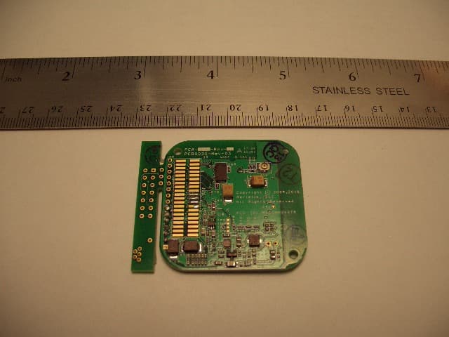
RKVSAM200TR
Jan 13, 2010Audio Streaming Module
Equipment Class
DTS - Digital Transmission System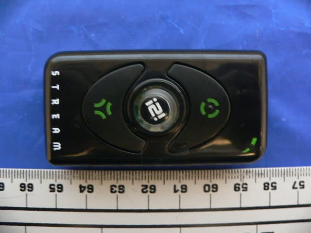
RKVI2I200
Feb 07, 2008I2i Stream Wireless Digital Audio Device
Equipment Class
DTS - Digital Transmission System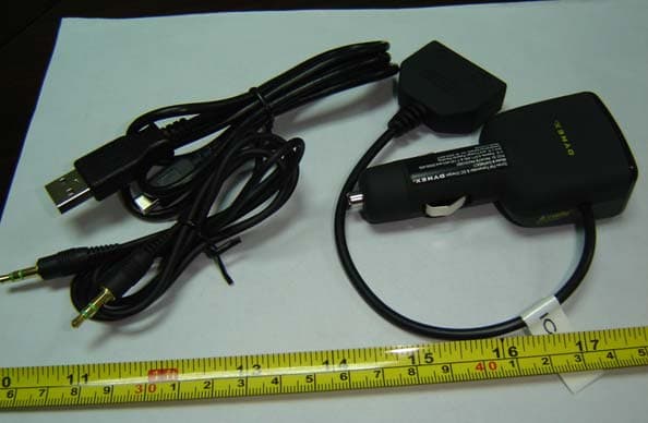
RKVATBPA5V350U
Oct 14, 2007FM Transmitter
Equipment Class
DXX - Part 15 Low Power Communication Device Transmitter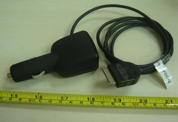
RKVATBPAC5V450
Oct 14, 2007FM Transmitter
Equipment Class
DXX - Part 15 Low Power Communication Device Transmitter
RKVAB350K
Feb 01, 2006Low Power FM Transmitter
Equipment Class
DXX - Part 15 Low Power Communication Device Transmitter