RKVI2I200I2i Stream Wireless Digital Audio Device
Aerielle, Inc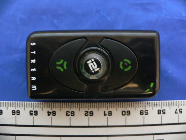
Click to zoom
Application Details
- Equipment Class
- DTS - Digital Transmission System
- Date of Grant
- Feb 07, 2008
- Application Purpose
- Original Equipment
- Date of Application
- Feb 07, 2008
- Equipment Note
- I2i Stream Wireless Digital Audio Device
- Frequency Range
- 2412.00000000 - 2464.00000000
- Company
- Aerielle, Inc
- Country
- United States
Documents & Files
Document Text
Text extracted from the exhibit documents filed with the FCC. Open a document above to read the original.
Users Manual
FCC INFORMATION This device complies with part 15 of the FCC Rules. Operation is subject to the following two conditions: 1) This device may not cause harmful interference, and 2) This device must accept any interference received, including interference that may cause undesired operation. Customer Service [email protected] Phone: 650.967.4047 ext. 200 The following marks are registered and/or unregistered trademarks owned by Aerielle Technologies, Inc: the i2i Stream logo; the Aerielle Enabled logo; the company logo for Aerielle, Inc.; i2iGear; Listen Together Wirelessly; Unleash Your Tunes; Aerielle; Aerielle Enabled; Simply Better Sound; i2i; i2i Stream; and Share Your Tunes. iPod is a registered trademark of Apple, Inc. All other marks are owned by third parties and may be registered in various jurisdictions. US Patent #7,120,403 and US and Foreign Patents Pending under license by Aerielle Technologies, Inc. i2i Stream is designed in the USA and manufactured to Aerielle, Inc. specifications in China. 2008 (c) Aerielle Technologies, Inc., 625 Ellis St., Ste 206, Mountain View, CA 94043, USA. GETTING STARTED CHARGING YOUR i2i STREAM Before using the i2i Stream, you need to fully charge the battery. 1. First, connect the i2i Stream to your PC or laptop USB port using the included USB Charging Cable. 2. The Red LED in the upper right hand corner of the i2iStream will start flashing. When the red LED stops flashing and is steadily on (after about 5-6 hours the first time) your i2i Stream is fully charged. 3. Disconnect the USB Charging Cable. The i2i Stream battery will last about 5 to 7 hours (depending on use) before needing to be recharged. SETTING UP YOUR i2i STREAM 1. Attach the lanyard loop to the i2i Stream on the back of the unit as shown. 2. Attach either the neck lanyard or the pocket clip to the lanyard connector. If using the neck lanyard, you can hang the Stream around your neck when using it. If using the pocket clip, you can clip the Stream to pockets, belt loop, or other areas on your clothing. 3. Select either the 12” or 28” audio cable to connect the i2i Stream to your audio player. Choose the length that’s comfortable for carrying your audio player and i2i Stream. 4. Connect the smaller plug of the audio cable to the jack on the bottom of the i2i Stream. Connect the larger plug into the headphone jack of your iPod®, MP3 player, or any audio device that has a standard 3.5mm stereo headphone jack. 5. Connect your favorite headphones to the headphone jack on the top of the i2i Stream. 6. Repeat the above on the second i2i Stream. You can add as many i2i Streams as you like for group streaming. 7. Turn on both i2i Streams by pressing the VOLUME CONTROL button for one second. The Battery Indicator will flash several times indicating the battery power level. 4 Blinks 75% or more of battery charge 3 Blinks 50%-75% of battery charge 2 Blinks 25%-50% of battery charge 1 Blink Less than 25% of battery charge BECOME THE BROADCASTER AND SEND MUSIC STREAMS 1. Select the Channel Color of your choice by pressing the Channel Button. See image below. Pick from: 2. Press the SEND button. The Channel button color will now blink, indicating that the i2i Stream is in broadcast mode. 3. Start playing songs on your media player. 4. You can now hear the music being played from your media player. You can adjust the volume by using the volume control on your media player. To mute the audio, press the volume control knob on the i2i Stream. TO SWITCH BROADCASTERS 1. You can easily switch back and forth between broadcasters and listeners. If you are a listener, switch to broadcast by selecting a new channel color and then press the SEND button. Once the Channel Button starts blinking, other i2i Stream users can then press RECEIVE and listen to the music being played on your media player. ADDITIONAL BROADCASTERS 1. Up to 3 broadcasters may operate within a 30 foot range of each other. Simply repeat the instructions above for becoming a broadcaster. Each of the three broadcasters must be on a different channel color. NOTE: Under certain conditions where a group of Streams are in close proximity to a strong home wireless network or WiFi hotspot, the number of broadcasting Streams might be limited to two instead of three. 2. Listeners can join in by selecting the channel color of any of the additional broadcasters and by pressing the RECEIVE button. Listeners can easily switch between broadcasters by using the Channel Button. TURNING THE POWER OFF 1. To conserve battery life, you should turn off your i2i Stream when not in use. Simply press the VOLUME CONTROL button for one second. The device is off when the Channel Button light turns off. 2. The i2i Stream also has an auto-off feature. The device will automatically turn off after several minutes of no music being played on an attached media player or audio source. BECOME A LISTENER AND RECEIVE MUSIC STREAMS FROM THE BROADCASTER ON THE SECOND i2i STREAM 1. Press the center button until the color matches the broadcaster’s i2i Stream. 2. Press the RECEIVE button. 3. You can now hear the music that is being played on the broadcaster’s media player. Press the i2i Stream Volume Control knob up or down to control the volume level. Press the volume control knob in to mute the audio. For faster charging, you can use the optional i2i Stream AC Charge Adapter and charge your i2i Stream using an AC Outlet. The AC Charge Adapter provides faster charging (about 2 hours). Visit www.i2iGear.com to purchase the AC Charge Adapter as well as many other i2i Stream accessory items. HOT TIP You can still listen to music being played from your media device without turning on or disconnecting the i2i Stream. The device provides “pass through” audio from your media player direct to your headphones. HOT TIP You do not even need a media player connected to the i2i Stream to listen to music from the broadcaster! HOT TIP You can also use two i2i streams for sending musi…
Text truncated - open the document above for the full version.
External Photos
Aerielle, Inc. FCC ID: RKVI2I200, IC: 7351A-I2I200 Report No.: R0801161 Page 45 of 48 FCC Part 15.247 and IC RSS-210 14 EXHIBIT C - EUT PHOTOGRAPHS 14.1 EUT Front Side View 14.2 EUT Back Side View
ID Label/Location Info
Aerielle, Inc. FCC ID: RKVI2I200, IC: 7351A-I2I200 Report No.: R0801161 Page 39 of 48 FCC Part 15.247 and IC RSS-210 12 EXHIBIT A – FCC & IC EQUIPMENT LABELING REQUIREMENTS 12.1 FCC § 2.925 Identification of equipment (a) Each equipment covered in an application for equipment authorization shall bear a nameplate or label listing the following: (1) FCC Identifier consisting of the two elements in the exact order specified in §2.926. The FCC Identifier shall be preceded by the term FCC ID in capital letters on a single line, and shall be of a type size large enough to be legible without the aid of magnification. Example: FCC ID XXX123. XXX—Grantee Code 123—Equipment Product Code 12.2 FCC ID Labeling Requirements as per FCC § 15.19 (a) In addition to the requirements in part 2 of this chapter, a device subject to certification, or verification shall be labeled as follows: (3) All other devices shall bear the following statement in a conspicuous location on the device: This device complies with part 15 of the FCC Rules. Operation is subject to the following two conditions: (1) This device may not cause harmful interference, and (2) this device must accept any interference received, including interference that may cause undesired operation. (4) Where a device is constructed in two or more sections connected by wires and marketed together, the statement specified above is required to be affixed only to the main control unit. If the EUT is integrated within another device then a label affixed to the host shall also state, “Contains FCC ID:XXXXXX” (5) When the device is so small or for such use that it is not practicable to place the statement specified under paragraph (a) of this section on it, the information required by this paragraph shall be placed in a prominent location in the instruction manual or pamphlet supplied to the user or, alternatively, shall be placed on the container in which the device is marketed. However, the FCC identifier or the unique identifier, as appropriate, must be displayed on the device. IC: XXXXXX-YYYYYYYY Where: • "XXXXXX-YYYYYYYY" is the certification number • "XXXXXX" is the Certificate Holder Number (CHN), made of at most 6 alphanumeric characters (A-Z, 0-9), assigned by Industry Canada; and • "YYYYYYYY" is the Unique Product Number (UPN), made of at most 8 alphanumeric characters (A-Z, 0-9) assigned by the applicant. • Note 1: The term "IC" before the equipment certification number only signifies that the Industry Canada technical specifications were met. • Note 2: Note 1 shall be conspicuously placed in the equipment user manual. • Note 3: Permitted alphanumeric characters used in the CHN and UPN are limited to capital letters (A-Z) and digits (0-9). Other characters, such as "#", "/" or "-", shall not be used. Aerielle, Inc. FCC ID: RKVI2I200, IC: 7351A-I2I200 Report No.: R0801161 Page 40 of 48 FCC Part 15.247 and IC RSS-210 12.3 Specifications: As per RSS GEN 5.2 Equipment Labeling: Equipment subject to certification under the applicable RSS, shall be permanently labeled on each item, or as an inseparable combination. The label must contain the following information for full compliance: (a) the certification number, prefixed by the term “IC:”; (b) the manufacturer's name, trade name or brand name; and (c) a model name or number. Equipment for which a certificate has been issued is not considered certified if it is not properly labeled. The information on the Canadian label can be combined with the manufacturer’s other labeling requirements. If the device size is too small to put a label, the label can be included in the user’s manual, upon agreement with Industry Canada. 12.4 Suggested FCC ID & IC Label 12.5 Proposed Label Location Model: I2I200 This device complies with part 15 of the FCC Rules. Operation is subject to the following two conditions: (1) This device may not cause harmful interference, and (2) this device must accept any interference received, including interference that may cause undesired operation. FCC ID: RKVI2I200 IC: 7351A-I2I200 Aerielle, Inc.
Internal Photos
Aerielle, Inc. FCC ID: RKVI2I200, IC: 7351A-I2I200 Report No.: R0801161 Page 46 of 48 FCC Part 15.247 and IC RSS-210 14.3 EUT Front Cover/ Chassis View 14.4 EUT PCB Side 1 View Aerielle, Inc. FCC ID: RKVI2I200, IC: 7351A-I2I200 Report No.: R0801161 Page 47 of 48 FCC Part 15.247 and IC RSS-210 14.5 EUT PCB Side 2 View 14.6 EUT PCB Side 2 View (RF Shielding Removed) Aerielle, Inc. FCC ID: RKVI2I200, IC: 7351A-I2I200 Report No.: R0801161 Page 48 of 48 FCC Part 15.247 and IC RSS-210 14.7 EUT Battery 14.8 Optional AC/DC Adapter
Test Report
Note: This test report is for the customer shown above and their specific product only. It may not be duplicated or used in part without prior written consent from Bay Area Compliance Laboratories Corp. This report must not be used by the customer to claim product certification, approval, or endorsement by NVLAP, NIST, or any agency of the Federal Government . FCC PART 15.247 INDUSTRY CANADA RSS-210, ISSUE 7, JUNE 2007 MEASUREMENT AND TEST REPORT For Aerielle, Inc. 625 Ellis Street, Suite 206 Mountain View, CA 94043 FCC ID: RKVI2I200 IC ID: 7351A-I2I200 Model: I2I200 Report Type: Original Report Product Type: 2.4 GHz Wireless Audio Transceiver Test Engineer(s): Xiao Ming Hu Report Number: R0801161 Testing Date(s): 2008-01-22, 2008-01-23 Report Date: 2007-01-31 Reviewed By: Boni Baniqued, Sr. RF Test Engineer Prepared By: (12) Bay Area Compliance Laboratories Corp. 1274 Anvilwood Ave. Sunnyvale, CA 94089, USA Tel: (408) 732-9162 Fax: (408) 732-9164 Aerielle, Inc. FCC ID: RKVI2I200, IC: 7351A-I2I200 Report No.: R0801161 Page 2 of 48 FCC Part 15.247 and IC RSS-210 TABLE OF CONTENTS 1 GENERAL INFORMATION .......................................................................................................................................4 1.1 PRODUCT DESCRIPTION FOR EQUIPMENT UNDER TEST (EUT) ............................................................................. 4 1.2 MECHANICAL DESCRIPTION OF EUT ................................................................................................................... 4 1.3 ANTENNA DESCRIPTION....................................................................................................................................... 4 1.4 EUT PHOTO......................................................................................................................................................... 4 1.5 OBJECTIVE........................................................................................................................................................... 5 1.6 RELATED SUBMITTAL(S)/GRANT(S)..................................................................................................................... 5 1.7 TEST METHODOLOGY.......................................................................................................................................... 5 1.8 MEASUREMENT UNCERTAINTY............................................................................................................................ 5 1.9 TEST FACILITY..................................................................................................................................................... 5 2 SYSTEM TEST CONFIGURATION ..........................................................................................................................7 2.1 JUSTIFICATION..................................................................................................................................................... 7 2.2 EUT EXERCISE SOFTWARE.................................................................................................................................. 7 2.3 SPECIAL ACCESSORIES......................................................................................................................................... 7 2.4 EQUIPMENT MODIFICATIONS...............................................................................................................................7 2.5 LOCAL SUPPORT EQUIPMENT LIST AND DETAILS................................................................................................ 7 2.6 INTERFACE PORTS AND CABLING......................................................................................................................... 7 2.7 TEST SETUP BLOCK DIAGRAMS........................................................................................................................... 8 3 SUMMARY OF TEST RESULTS ...............................................................................................................................10 4 FCC §15.247 (i) and §2.1091, IC RSS-Gen 5.5 & RSS-102 - RF EXPOSURE .........................................................11 4.1 APPLICABLE STANDARD.................................................................................................................................... 11 4.2 MPE PREDICTION.............................................................................................................................................. 12 4.3 TEST RESULT..................................................................................................................................................... 12 5 FCC §15.203, IC RSS-Gen §7.1.4 – ANTENNA REQUIREMENT ..........................................................................13 5.1 APPLICABLE STANDARD.................................................................................................................................... 13 5.2 RESULT.............................................................................................................................................................. 13 6 FCC §15.207, IC RSS-Gen §7.2.2 - CONDUCTED EMISSIONS .............................................................................14 6.1 SECTION 15.207 & RSS-GEN 7.2.2 CONDUCTED LIMITS:................................................................................... 14 6.2 TEST SETUP....................................................................................................................................................... 14 6.3 TEST EQUIPMENT LIST AND DETAILS................................................................................................................. 14 6.4 TEST PROCEDURE.............................................................................................................................................. 15 6.5 ENVIRONMENTAL CONDITIONS..........................................…
Text truncated - open the document above for the full version.
Test Setup Photos
Aerielle, Inc. FCC ID: RKVI2I200, IC: 7351A-I2I200 Report No.: R0801161 Page 41 of 48 FCC Part 15.247 and IC RSS-210 13 EXHIBIT B - TEST SETUP PHOTOGRAPHS 13.1 Conducted Emissions –Front View 13.2 Conducted Emissions – Side View Aerielle, Inc. FCC ID: RKVI2I200, IC: 7351A-I2I200 Report No.: R0801161 Page 42 of 48 FCC Part 15.247 and IC RSS-210 13.3 Receiver Radiated Emissions – Front View 13.4 Receiver Radiated Emissions – Rear View Aerielle, Inc. FCC ID: RKVI2I200, IC: 7351A-I2I200 Report No.: R0801161 Page 43 of 48 FCC Part 15.247 and IC RSS-210 13.5 Transmitter Radiated Spurious Emissions – Front View Aerielle, Inc. FCC ID: RKVI2I200, IC: 7351A-I2I200 Report No.: R0801161 Page 44 of 48 FCC Part 15.247 and IC RSS-210 13.6 Transmitter Radiated Spurious Emissions – Rear View
Contact Information
Applicant
Art Cohen(President & CEO)
Test Firm
Bay Area Compliance LaboratoryJohn Chan
Technical Specifications
| # | Rule Parts | Frequency Range | Power Output |
|---|---|---|---|
| 1 | 15C | 2.41 GHz - 2.46 GHz | 5.00 mW |
Other Applications from Aerielle, Inc
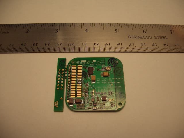
RKVSAM200TR
Jan 13, 2010Audio Streaming Module
Equipment Class
DTS - Digital Transmission System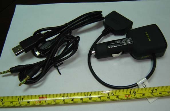
RKVATBPA5V350U
Oct 14, 2007FM Transmitter
Equipment Class
DXX - Part 15 Low Power Communication Device Transmitter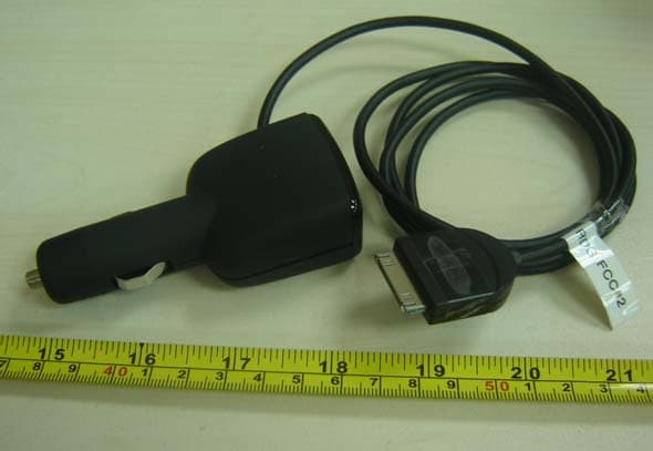
RKVATBPAC5V450
Oct 14, 2007FM Transmitter
Equipment Class
DXX - Part 15 Low Power Communication Device Transmitter
RKVAB450K
Feb 01, 2006Low Power FM Transceiver
Equipment Class
DXX - Part 15 Low Power Communication Device Transmitter
RKVAB350K
Feb 01, 2006Low Power FM Transmitter
Equipment Class
DXX - Part 15 Low Power Communication Device Transmitter