RLQSB2008Bluetooth Speaker
Zhongshan K-mate Electronics Co. Ltd.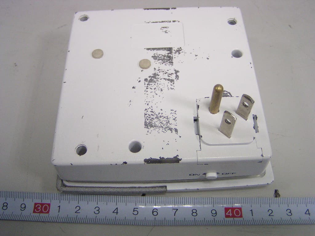
Click to zoom
Application Details
- Equipment Class
- DSS - Part 15 Spread Spectrum Transmitter
- Date of Grant
- Mar 05, 2008
- Application Purpose
- Original Equipment
- Date of Application
- Mar 05, 2008
- Equipment Note
- Bluetooth Speaker
- Frequency Range
- 2402.00000000 - 2480.00000000
- Country
- China
Documents & Files
Document Text
Text extracted from the exhibit documents filed with the FCC. Open a document above to read the original.
Users Manual
1 User Manual Operating SB2008 1、Connecting the SB2008 to power source (AC:100-240v). Then slide the switch to ON position. And the unit will enter into automatic searching mode while the green LED flashing rapidly. 2、Pressing the transmitter supplied by K-mate until turns the unit on. The transmitter will enter into pairing mode while the blue LED flashing rapidly. 3、The transmitter is paired with the SB2008 if the blue LED is steadily lit. The communicate range is 10 meters. Then you can connect the transmitter to audio source. 4、Connecting the transmitter to 3.5 audio source players. Enjoy the music. 5、When the battery charge low in transmitter, the red LED will be lit. And you should recharge the transmitter. To charge the transmitter by inserting the transmitter adapter into the USB port of transmitter. After charging is finished, the red LED turns blue. 6、If disconnect the SB2008 with power source, the wireless connection will also disconnect. And the green LED turns dark. 7、Pressing the ON/OFF of transmitter until turns it off. The LED indicator will be turned dark. However, SB2008 will be in searching mode. And its green LED will flash. 8、You can pair the SB2008 with other Bluetooth devices. The PIN code is “0000”. You can enjoy music by selecting “Musicfan”. 9、On the operating panel in the SB2008, there is a light-sensitive LED. It can detect the intensity indoor. When the room is dark, a blue LED will be turned on. And the LED will be turn dark when there is sufficient light in the room. Therefore when using the unit please prevent form any covering the LED. 10、 You can turn SB2008 off by sliding the switch to off position. Specification: Power output: 2W+2W HD: 10 %( Max. Power) 1.5W+1.5W HD: 1 %( Rated power) Input sensitivity: 300-500mV Impedance:8Ω Voltage input: 100V-240V AC input Current input: 0.15A MAX DC Output: 6.5V 800mA 2 FCC Warning Statement: This device complies with part 15 of the FCC Rules. Operation is subject to the following two conditions: (1) This device may not cause harmful interference, and (2) this device must accept any interference received, including interference that may cause undesired operation. Changes or modifications to this unit not expressly approved by the party responsible for compliance will void the user’s authority to operate the equipment. Any change to the equipment will void FCC grant. This equipment has been tested and found to comply with the limits for a Class B digital device, pursuant to part 15 of the FCC Rules. These limits are designed to provide reasonable protection against harmful interference in a residential installation. This equipment generates, uses and can radiate radio frequency energy and, if not installed used in accordance with the instructions, may cause harmful interference to radio communications. However, there is no guarantee that interference will not occur in a particular installation. If this equipment does cause harmful interference to radio or television reception, which can be determined by turning the equipment off and on, the user is encouraged to try to correct the interference by one or more of the following measures: --Reorient or relocate the receiving antenna. --Increase the separation between the equipment and receiver. --Connect the equipment into an outlet on a circuit different from that to which the receiver is connected. --Consult the dealer or an experienced radio/TV technician for help. The equipment compliance with FCC radiation exposure limit set forth for uncontrolled Environment.
Block Diagram
Block Diagram 2.402-2.4835GHz BLUETOOTH MODULE Antenna Flash BT chip Crystal Balance LED Power Managemen Audio Output
Cover Letter(s)
FCC Authorization Date: 2008-1-31 FEDERAL COMMUNICATIONS COMMISSIONS Authorization and Evaluation Division 7435 Oakland Mills Road Columbia, MD 21046 Subject: Agent Authorization To whom it may concern: We Zhongshan K-mate Electronics Co. Ltd . , the undersigned, Hereby authorizes Bay Area Compliance Laboratory Corporation to act on its behalf in all matters relating to application for Equipment authorization, including the signing of all documents relating to these matters. All acts carried out by Bay Area Compliance Laboratory Corporation on our behalf shall have the same effect as our own action. We, the undersigned, hereby certify that we are not subject to a denial of federal benefits, that includes FCC benefits, pursuant to Section 5301 of the Anti-Drug Abuse Act of 1988, 21 U.S.C. 853(a). This authorization is valid until further written notice from the applicant. Sincerely Yours, Signature: Typed or Printed Name: MingJun’OuYang Title: ElectronicEngineer Company Name: Zhongshan K-mate Electronics Co. Ltd.
Cover Letter(s)
Non-Confidential Authorization Date: 2008-1-31 FEDERAL COMMUNICATIONS COMMISSIONS Authorization and Evaluation Division 7435 Oakland Mills Road Columbia, MD 21046 Subject: Non-Confidentiality Request regarding application for certification of FCC ID: (RLQSB2008). To: whom it may concern, We Zhongshan K-mate Electronics Co. Ltd. . confirm that all the information accompanying this application as outlined below are permitted to release to the public. Product Name: Bluetooth Speaker FCC ID:RLQSB2008 Sincerely Yours, Signature: Typed or Printed Name: MingJun’OuYang Title: ElectronicEngineer Company Name: Zhongshan K-mate Electronics Co. Ltd. Form 05
External Photos
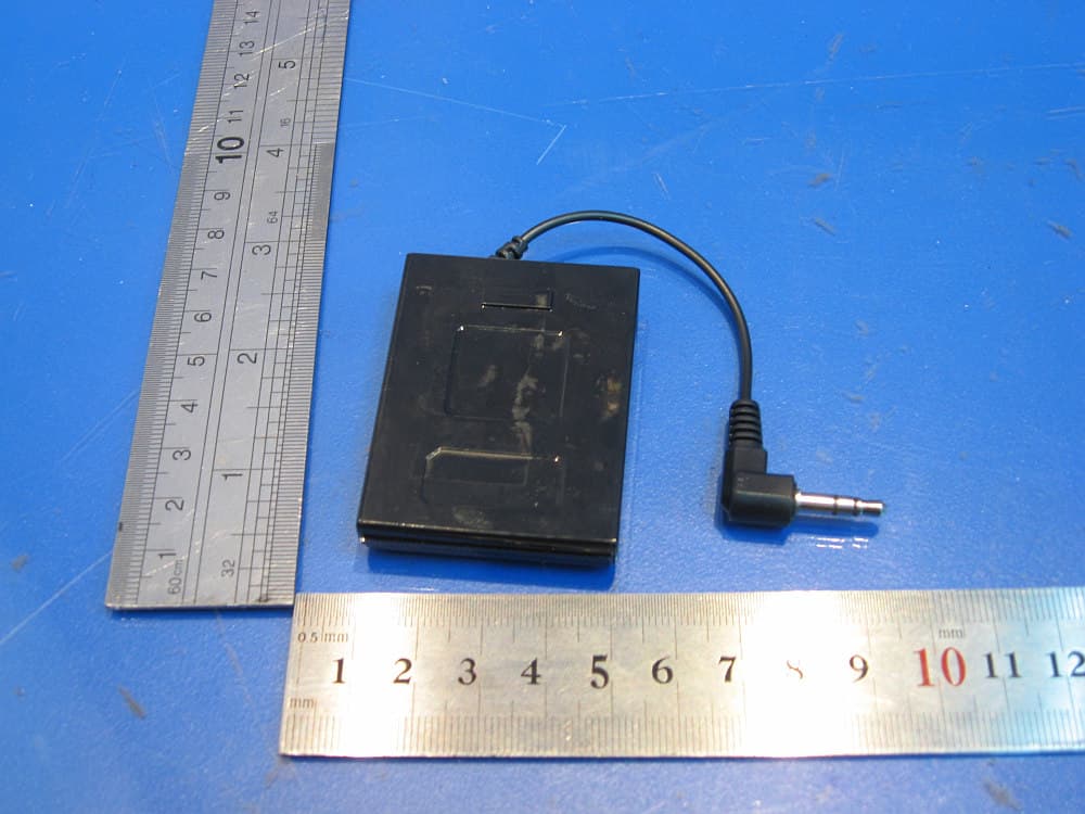
External Photos EUT (White Color) – Top View EUT (White Color) – Bottom View EUT (Red Color) – Top View EUT (Red Color) – Bottom View EUT (Black Color) – Top View EUT (Black Color) – Bottom View
ID Label/Location Info
EXHIBIT A - FCC ID LABELING AND LOCATION Suggested FCC ID Label Suggested FCC ID Label Location FCC ID: RLQSB2008
Internal Photos
Internal Photos EUT (White Color) –Uncovered View EUT (White Color) – Loudhailer View EUT (White Color) –Main Board Top Components View EUT (White Color) –Main Board Bottom Components View EUT (White Color) –Power Board Top Components View EUT (White Color) –Power Board Bottom Components View (1) EUT (White Color) –Power Board Bottom Components View (2) EUT (Red Color) –Uncovered View EUT (Red Color) –Main Board Top Components View EUT (Red Color) –Main Board Bottom Components View EUT (Red Color) –Power Board Top Components View EUT (Red Color) –Power Board Bottom Components View (1) EUT (Red Color) –Power Board Bottom Components View (2) EUT (Black Color) –Uncovered View EUT (Black Color) –Loudhailer View EUT (Black Color) –Main Board Top Components View EUT (Black Color) –Main Board Bottom Components View EUT (Black Color) –Power Board Top Components View EUT (Black Color) –Power Board Bottom Components View (1) EUT (Black Color) –Power Board Bottom Components View (2)
Operational Description
Cricuit description This is power management circuit, it can output +3V for the Bluetooth Module. As we can see this circuit, the L301 is a inductance which will damage itself when the power from J302 is strong enough to protect the whole circuit. And the C301E301C302E303C304 is capacitance filter , which can make the power stable. The U301 is a high performance LDO which could change the input voltage into +3V and supply power for the Bluetooth Module. This circuit could display the working state of Bluetooth Module though D301. The GPIO11 which is controlled by software output high or low voltage to make the Q301 on or off, so the LED will flashing or lighting. This is the important part of the whole circuit. The BCM2037 wireless audio module supports the Bluetooth 2.0 specification with enhanced data rate (EDR) enabling peak data rates of 3 Mbps, while providing full backward compatibility to Bluetooth 1.2 and Bluetooth 1.1 specifications. High integration with low power operation are ideal for battery-operated wireless stereo and wireless mono consumer audio applications. The BCM2037 has sufficient processing performance to simultaneously manage the user interface, maintain full Bluetooth protocol stack operation and execute key audio algorithms. This high performance is enabled by a 32-bit ARM7 CPU with high peak clock speeds and deep on-chip memory allowing zero-wait-state execution of computationally intensive audio algorithms. Key algorithms are supported by application-specific hardware accelerators, further increasing BCM2037 computational capabilities, while reducing system power consumption. These powerful features eliminate the need for a separate external DSP, reducing the bill of materials, power consumption and total footprint. The Bluetooth Module receives hoping frequency signal though Antenna, and change it into audio signal. So this can realize wireless transmission, and enjoy the music freely.
Schematics
1234 A B C D 4321 D C B A 1 2 3 4 5 6 7 8 9 10 11 12 13 14 15 1626 27 28 29 30 31 32 33 34 35 36 37 38 39 40 41 4 2 4 8 4 9 5 0 4 6 4 5 4 4 4 3 1 7 1 8 1 9 2 0 2 1 2 2 2 3 2 4 2 5 4 7 U2 KMBT005 E306 4.7uF E307 4.7uF C306 0.1uF C307 0.1uF Vdd Vdd Rout+ Lout+ UART_TX UART_RX C321 NC C322 NC L302 0Ω ANT12402-2480MHz R314 470K R315 220K Vdd GPIO20 E310 10uF E309 10uF C313 220pF R324 47K R323 47K C312 220pF GPIO5 GPIO10 GPIO17 GPIO11 GPIO2 GPIO21 Q301 3904 Vcc R303 1K C301 0.1uF L301 1uH E301 220uF/10V E302 NC Vcc R304 47K GPIO11 VDD 1 GND 2 CE/ 3 4 4 VCC 5 U1 XC6204B302MR R302 47K C302 0.1uF C303 NC C304 0.1uF E303 4.7uF Vdd Vdd Vdd GPIO5 GPIO10 GPIO17 GPIO21 R311 NC R312 10K GPIO20 1 2 J302 CON2 C305 0.1uF R307 10K R306 10K R301 10K R305 10K R308 10K R309 10K R310 10K R313 10K D301 LED PDF 1234 A B C D 4321 D C B A Q1 9014 Q2 8550 R? 4.7R R28 100R R9 100R R? 4.7K R7 27K R4 100K R6 150K LED1 LED LED2 LED LED3 LED V+LED R5 100K P G 1 N C 2 N C 3 N C 4 OUT+ 5 OUT- 6 V C C 7 IN1 8 N C 9 MUTE 10 STANBY 11 N C 1 2 N C 1 3 SGND 14 N C 1 5 N C 1 6 IN2 17 V C C 1 8 OUT2- 19 OUT2+ 20 N C 2 1 N C 2 2 N C 2 3 PG 24 IC1 TDA-7266P 1 2 CN10 R-OUT 1 2 CN11 L-OUT R22 4.7K R23 4.7K R26 10K R25 10K R27 47K R24 10K CC1 153 CC18 153 CC19 104 C7 1000uF C8 100uf V+ R1 4.7R R2 4.7R CC3 104 CC2 104 R L CC25 222 CC26 222 1 2 3 4 CN8 4P LED GND GND
Test Report
Note: This test report is for the customer shown above and their specific product only. It may not be duplicated or used in part without prior written consent from Bay Area Compliance Laboratories Corp. (Shenzhen) This report must not be used by the customer to claim product certification, approval, or endorsement by NVLAP, NIST, or any agency of the Federal Government. FCC PART 15.247 MEASUREMENT AND TEST REPORT For Zhongshan K-mate Electronics Co. Ltd. Fu Wan Industrial Zone Sun Wen East Road Zhongshan, China FCC ID: RLQSB2008 This Report Concerns: Original Report Equipment Type: Bluetooth Speaker Test Engineer: Phoenix Liu Report No.: RSZ07110701 Test Date: 2008-01-16 to 2008-03-05 Report Date: 2008-03-06 Reviewed By: EMC Manager: Green Xu Prepared By: Bay Area Compliance Laboratories Corp. (Shenzhen) 6/F, the 3rd Phase of WanLi Industrial Building, ShiHua Road, FuTian Free Trade Zone Shenzhen, Guangdong, China Tel: +86-755-33320018 Fax: +86-755-33320008 Zhongshan K-mate Electronics Co. Ltd. FCC ID: RLQSB2008 Report No.: RSZ07110701 Page 2 of 40 FCC Part 15.247 Test Report TABLE OF CONTENTS GENERAL INFORMATION.......................................................................................................................................4 PRODUCT DESCRIPTION FOR EQUIPMENT UNDER TEST (EUT) .....................................................................................4 OBJECTIVE...................................................................................................................................................................4 RELATED SUBMITTAL(S)/GRANT(S).............................................................................................................................4 TEST METHODOLOGY..................................................................................................................................................4 TEST FACILITY.............................................................................................................................................................4 SYSTEM TEST CONFIGURATION ..........................................................................................................................6 DESCRIPTION OF TEST CONFIGURATION......................................................................................................................6 EUT EXERCISE SOFTWARE..........................................................................................................................................6 SPECIAL ACCESSORIES.................................................................................................................................................6 EQUIPMENT MODIFICATIONS.......................................................................................................................................6 LOCAL SUPPORT EQUIPMENT LIST AND DETAILS........................................................................................................6 CONFIGURATION OF TEST SETUP.................................................................................................................................7 BLOCK DIAGRAM OF TEST SETUP................................................................................................................................7 SUMMARY OF TEST RESULTS ...............................................................................................................................8 CFR47 §15.203 - ANTENNA REQUIREMENT.........................................................................................................9 STANDARD APPLICABLE..............................................................................................................................................9 ANTENNA CONNECTOR CONSTRUCTION......................................................................................................................9 CFR47 §15.207 (a) - CONDUCTED EMISSIONS ...................................................................................................10 MEASUREMENT UNCERTAINTY..................................................................................................................................10 EUT SETUP................................................................................................................................................................10 EMI TEST RECEIVER SETUP.......................................................................................................................................11 TEST EQUIPMENT LIST AND DETAILS.........................................................................................................................11 TEST PROCEDURE......................................................................................................................................................11 TEST RESULTS SUMMARY..........................................................................................................................................11 TEST DATA................................................................................................................................................................12 PLOT(S) OF TEST DATA..............................................................................................................................................12 CFR47 §15.205, §15.209, §15.247 - RADIATED EMISSIONS................................................................................15 APPLICABLE STANDARD............................................................................................................................................15 MEASUREMENT UNCERTAINTY..................................................................................................................................15 EUT SETUP.............................................................................................................................................................…
Text truncated - open the document above for the full version.
Test Setup Photos
Test Setup Photos Conducted Emissions - Front View Conducted Emissions - Side View Radiated Emissions - Front View (Below 1G) Radiated Emissions - Rear View (Below 1G) Radiated Emissions - Front View (Above 1GHz) Radiated Emissions - Rear View (Above 1GHz)
Contact Information
Applicant
Christine Wu(Sales Manager)
Test Firm
Bay Area Compliance Laboratory Corp. (Shenzhen)John Chan
Technical Specifications
| # | Rule Parts | Frequency Range | Power Output |
|---|---|---|---|
| 1 | 15C | 2.40 GHz - 2.48 GHz | 525.00 µW |
Other Applications from Zhongshan K-mate Electronics Co. Ltd.
RLQBH1000-1C
Feb 19, 2008Stereo Bluetooth Adaptor
Equipment Class
DSS - Part 15 Spread Spectrum Transmitter
RLQBH501
Oct 30, 2007Bluetooth Earphone
Equipment Class
DSS - Part 15 Spread Spectrum Transmitter
RLQAT400-2
Jul 17, 2006Audio FM Transmitter
Equipment Class
DXX - Part 15 Low Power Communication Device Transmitter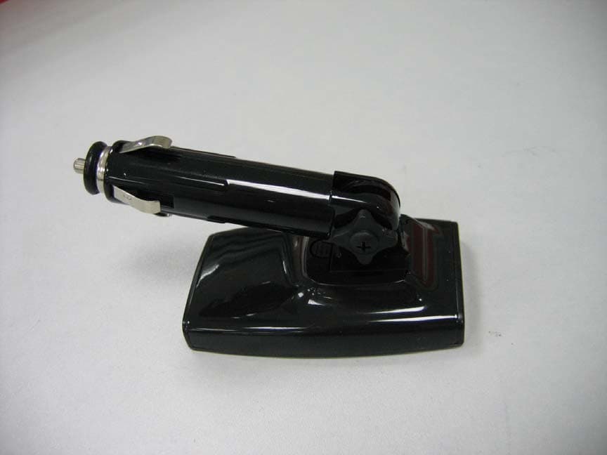
RLQAT600
Jun 12, 2006FM Transmitter Holder & Car Charger for iPod Nano
Equipment Class
DXX - Part 15 Low Power Communication Device Transmitter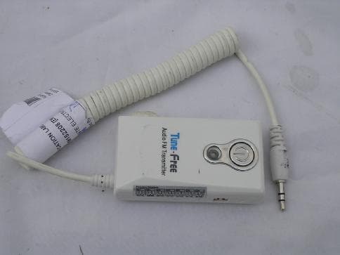
RLQAT100
Nov 10, 2004Audio FM Transmitter
Equipment Class
DXX - Part 15 Low Power Communication Device Transmitter