RNB-A2400Networking Device
Sensicast Systems, Inc.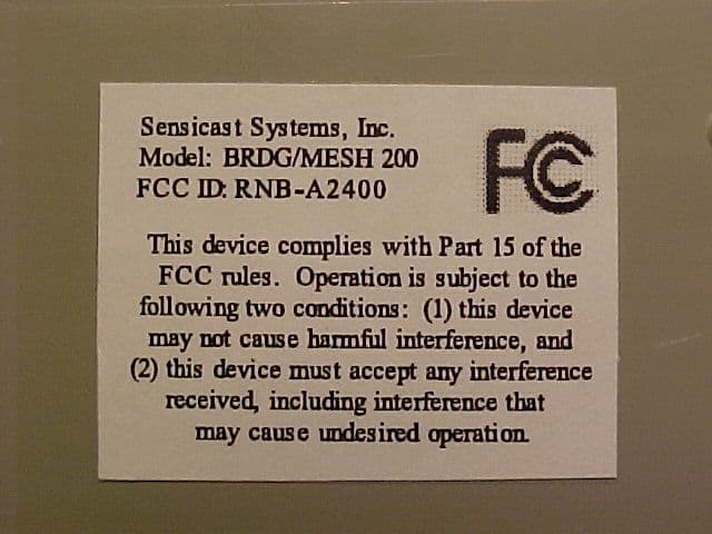
Click to zoom
Application Details
- Equipment Class
- DTS - Digital Transmission System
- Date of Grant
- Jan 03, 2006
- Application Purpose
- Original Equipment
- Date of Application
- Jan 03, 2006
- Equipment Note
- Networking Device
- Frequency Range
- 2405.00000000 - 2475.00000000
- Company
- Sensicast Systems, Inc.
- Country
- United States
Documents & Files
Document Text
Text extracted from the exhibit documents filed with the FCC. Open a document above to read the original.
Users Manual
A2400 MESH/BRIDGE NODES VERSION 2.0 HARDWARE MANUAL A2400 Mesh/Bridge Nodes VERSION 2.0 ___________________________________________________________________________________ Sensicast Systems, Inc. 220-3 Reservoir Street Needham, MA 02494 Phone 781.453.2555 [email protected] ______________________________________________________________________________________________________ www.sensicast.com 2 Part # 1600 – Hardware Manual Copyright 2005 Sensicast Systems, Inc. All rights reserved. Sensicast, SensiMesh, Sensicast Object Alarm System, Sensicast OAS, Sensicast Environmental Monitoring System, and Sensicast EMS are trademarks of Sensicast Systems, Inc. in the United States and/or other countries. All other trademarks are property of their respective owners. In the interest of product improvement, information and specifications herein are subject to change without notice. _____________________________________________________________________________________ www.sensicast.com 3 FCC Statement The A2400 equipment complies with Part 15 of the FCC Rules. Operation is subject to the following two conditions: (1) This device may not cause harmful interference; and (2) This device must accept any interference received, including interference that may cause undesired operation. FCC Caution: Any changes or modifications not expressly approved by Sensicast could void the user’s authority to operate this equipment. FCC RF Radiation Exposure Statement This device must operate with a separation distance of at least 20 cm from all persons and must not be co-located or operated in conjunction with any other antenna or transmitter. FCC Labeling: The device is labeled with its own FCC ID number (RNB-A2400). If this number is not visible when the module is installed inside another device, then the outside of the device into which the module is installed must also display a label with the following wording: “Contains FCC ID: RNB-A2400” _____________________________________________________________________________________ www.sensicast.com 4 O V E R V I E W, S A F E T Y, A N D S T O R A G E I N F O R M A T I O N www.sensicast.com 1-1 Safety Information This chapter provides important safety information for using your A2400 SensiNet system. Important Safety Information Use only Sensicast specified battery packs. Inspect battery pack prior to use and do not use if there is any evidence of leakage or deformity. Do not operate in an explosive environment. If battery charge is below 2V, remove or replace battery to prevent the possibility of leakage or damage. Chapter M E S H A N D B R I D G E N O D E S www.sensicast.com 2-1 A2400 Mesh/Bridge Nodes This chapter describes the hardware features of Mesh/Bridge nodes. Sensicast Mesh nodes can function either as network coordinators or as sensing/actuating nodes, depending on configuration. As a coordinator, the Mesh node automatically configures itself into a wireless mesh network with redundant connections to all leaf nodes and routing tables for all mesh nodes within connectivity range. To configure as a sensing/actuating node, the Mesh node must be combined with the appropriate interface card and/or firmware so that it can wirelessly transmit data from third-party sensors and receive control commands for device actuation. The Mesh node supports a completely wireless, self-configuring, self-healing, power managed sensor network. Sensicast Bridge nodes are specialized Mesh nodes that route data between the wireless mesh network and a host computer or LAN via Ethernet or USB connections. Components and Functions The primary components of a Mesh/Bridge node include the node itself, the battery pack, the power supply, and the interface connection, each of which is described below. Node The node is comprised of the node circuit board inside a two-piece plastic housing. Battery Pack The Sensicast-supplied 3V battery pack is used as a backup power for the Mesh/Bridge node in case of an external power disruption. This battery pack should be secured during operation inside the case as supplied. Power Supply The A2400 Mesh/Bridge node will accept the following voltage inputs: 1. 7.5VDC to 30VDC through a 3 pin terminal block. 2. 12VAC to 24VAC through a 3 pin terminal block. 3. 5VDC-7.5VDC through a barrel connector. 4. Ethernet / USB Connections The A2400 Bridge uses a standard RJ-45 jack for Ethernet connection to a network and a Standard USB jack for USB connection to a local PC. Only 1 of these connections can be used at a time. _____________________________________________________________________________________ www.sensicast.com 5 MESH / Bridge Node Note: Radio section is loaded on the back-side of the PCB. _____________________________________________________________________________________ www.sensicast.com 6 Battery Back-Up Connection Interface Board Connector USB Connector (Bridge) Ethernet Connector (Bridge) 6 Volt Power Connection 12/24 Volt Power Connection
Cover Letter(s)
fft$.~D~I~~ FCCCONFIDENTIALITY Date:03/07/2005Time:14:00EST To:FCCAuthorization&EvaluationDivision 7435OaklandMillsRoad Columbia,MD21045-0429 From:H.JeffGamer VicePresidentofEngineeringandOperations Phone:781-453-2555 Fax:781-453-0601 Applicant:SensicastSystems,Inc.E-Mail:[email protected] Subject:RequestforNondisclosureforFCCID:RNB-A2400. ToWhomIt MayConcern: Pursuantto47CFRSection0.459,SensicastSystems,Inc.herebyrequestsnondisclosureand confidentialtreatmentofthefollowingmaterialssubmittedinsupportofFCCcertification applicationforFCCID#RNB-A2400. a.SchematicDiagrams b.OperationalDescription c.BlockDiagram Abovematerialscontaintradesecrets,proprietaryandtechnicalinformationwhichwould customarilybeguardedfromcompetitorsunder47CFRsection0.457(d)(2).Disclosureor publicationofanyportionofthiscompanyconfidentialmaterialtootherpartiescouldcause substantialcompetitiveharmandprovideunjustifiedbenefitsforcompetitors. SensicastSystems,Inc.understandsthatpursuantto47CFRsection0.457(d)(1)(ii)disclosure oftheapplicantandallaccompanyingdocumentationwillnotbemadebeforethedateofthe grant. SensicastSystems,Inc. 220-3ReservoirSt. Needham,MA02494 S7l~~ H.JeffGamer VicePresidentEngineeringandOperations SensicastSystems,Inc. P: 781.453.2555 F:781.453.0601 http://www.sensicast.com *
External Photos
Sensicast Systems, Inc. A2400 Wireless Mesh Sensor Networks FCC ID#: RNB—A2400 Photo One – External Front View Sensicast Systems, Inc. A2400 Wireless Mesh Sensor Networks FCC ID#: RNB-A2400 Photo Two – External Back View, showing FCC ID Label Sensicast Systems, Inc. A2400 Wireless Mesh Sensor Networks FCC ID#: RNB-A2400 Photo Three – External FCC ID Label Shown
ID Label/Location Info
Trademarks - Copyrights© - Warranties - Returns Home | Inkjet Prices | Laser Prices | Order Form | FAQ | Tech Support | Samples | Contact Us Inkjet Labels. Laser Labels. Waterproof Labels. Any Size, Any Shape. No Die Charge on Short Run Jobs. Laser Cardstock. Inkjet Cardstock. Waterproof Paper. Dozens of Materials. Laser 102250 Outdoor Indoor White Polyester Perm Product Information Description: This label features a standard pressure construction including a 2 mil laser-print a polyester facestock that has excellent he resistance and dimensional stability. Thi features a specialty moderately aggres s removable adhesive that shows good in high shear strength, high removable str e excellent clarity. The clay-coated kraft li been coated one side to give a controlle Facestock 2 mil white top-coated polyester with a very smooth matte finish. It has e tear strength, heat resistance and dimensional stability while the top-coat excellent laser toner receptivity. Caliper 2 mil Opacity 75% Adhesive Clear acrylic adhesive featuring good removability on a wide range of su including corrugated and many plastic surfaces. Coat weight 1.0 cwt Min. application temp: +40 F Indirect Food: Yes Min. service temp: -65 F Direct Food: No Max. service temp: +150 F UL Approved: Ye s Note: For best bonding conditions, application surface should be at room ature or higher. Low temperature surfaces, below +40F can cause the ad become so firm that it will not develop maximum contact with the substra initial bonds can be achieved through increased rubdown pressure. In o a true measure of the adhesive’s effectiveness, the label should be appli allowed to bond a minimum of 24 hours prior to evaluation. Liner Clay-coated lay-flat liner which has been silicone coated one side to give controlled release. Caliper: 4.5 mils Weight: 74# The above are typical technical values and are given in good faith based upon our most u p knowledge and experience. As the products are used outside our control we cannot take responsibility for any damage that may be caused using the product. In every case, user s determine before using any product in full-scale production, or in any way, whether such pr suitable for user’s intended use for their particular purpose under their own operating condi Home | Inkjet Prices | Laser Prices | Order Form | FAQ | Tech Support | Samples | Contact Us Page 1 of 2102250 Outdoor Indoor White Polyester Perm 3/8/2005http://www.rippedsheets.com/laser/info/102250.html Rippedsheets.com Site Index Page 2 of 2102250 Outdoor Indoor White Polyester Perm 3/8/2005http://www.rippedsheets.com/laser/info/102250.html
Internal Photos
Sensicast Systems, Inc. A2400 Wireless Mesh Sensor Networks FCC ID#: RNB-A2400 Photo One – Internal Open for Inspection Sensicast Systems, Inc. A2400 Wireless Mesh Sensor Networks FCC ID#: RNB-A2400 Photo Two – Internal Sensicast Systems, Inc. A2400 Wireless Mesh Sensor Networks FCC ID#: RNB-A2400 Photo Three – Internal Sensicast Systems, Inc. A2400 Wireless Mesh Sensor Networks FCC ID#: RNB-A2400 Photo Four – Internal Sensicast Systems, Inc. A2400 Wireless Mesh Sensor Networks FCC ID#: RNB-A2400 Photo Five – Internal Sensicast Systems, Inc. A2400 Wireless Mesh Sensor Networks FCC ID#: RNB-A2400 Photo Six – Internal
RF Exposure Info
L.S. Compliance, Inc. Page 47of 51 Test Report Number: 304553-Tx-TCB-v1 Prepared For: Sensicast Systems, Incorporated 23. MPE Calculations The MPE calculations are based on 0 dBi declared antenna gain. Note: Empirically determined gain for the PCB trace antenna used in this product is approximately – 5.5 dBi Prediction of MPE limit at a given distance Equation from page 18 of OET Bulletin 65, Edition 97-01 where:S = power density P = power input to the antenna G = power gain of the antenna in the direction of interest relative to an isotropic radiator R = distance to the center of radiation of the antenna Maximum peak output power at antenna input terminal:14.60 (dBm) Maximum peak output power at antenna input terminal:28.840 (mW) Antenna gain(typical):0 (dBi) Maximum antenna gain:1.000 (numeric) Prediction distance:20 (cm) Prediction frequency:2400 (MHz) MPE limit for uncontrolled exposure at prediction frequenc y:1(mW/cm^2) Power density at prediction frequency:0.005738(mW/cm^2) Maximum allowable antenna gain:22.4 (dBi) 20cm =22.4 dB Margin of Compliance at 2 4R PG S π =
Test Report
L.S. Compliance, Inc. W66 N220 Commerce Court Cedarburg, WI 53012 262-375-4400 Fax: 262-375-4248 COMPLIANCE TESTING OF : Sensicast A2400 Coordinator Prepared For: Sensicast Systems Incorporated Attention: Mr. Jay Werb 220-3 Reservoir Street Needham, MA 02494 Test Report Number: 304553-Tx-TCB-v1 Test Dates: February 16 TH through August 18 TH , 2005 All results of this report relate only to the items that were tested. This report is not to be reproduced, except in full, without written approval of L. S. Compliance, Inc. L.S. Compliance, Inc. Page 2of 51 Test Report Number: 304553-Tx-TCB-v1 Prepared For: Sensicast Systems, Incorporated Table of Contents Section Description Page Index 1 L. S. Compliance in Review 3 2 A2LA Certificate of Accreditation 4 3 Validation Letter-U.S. Competent Body for EMC Directive 89/336/EEC 5 4 Signature Page 6 5 Product and General Information 7 6 Introduction 7 7 Product Description 8-9 8 Test Requirements 10 9 Summary of Test Report 10 10 Radiated Emissions Test 11-24 11 Band-Edge Measurements 25-26 12 Occupied Bandwidth 27 13 Conducted RF Emissions Test on AC Power Line 28-32 14 Power Output 15.247 (b) 33-34 15 Spurious Emissions 15.247 (d) 35-36 16 Spectral Density 37-38 17 Minimum Channel Separation 39-41 18 Channel Occupancy 42-44 19 Equal Channel Usage 45 20 Pseudorandom Hopping Pattern 45 21 Receiver Synchronization and Input Bandwidth 45 22 Frequency and Power Stability over Voltage and Temperature Variations 46 23 MPE Calculations 47 Appendix A Test Equipment List 48 B Antenna Specification Sheet 49 C Firmware and Setup Instructions 50-51 L.S. Compliance, Inc. Page 3of 51 Test Report Number: 304553-Tx-TCB-v1 Prepared For: Sensicast Systems, Incorporated 1. L. S. Compliance In Review L.S. Compliance - Accreditations and Listing’s As an EMC Testing Laboratory, our Accreditation and Assessments are recognized through the following: A2LA – American Association for Laboratory Accreditation Accreditation based on ISO/IEC 17025 : 1999 with Electrical (EMC) Scope of Accreditation A2LA Certificate Number: 1255.01 Federal Communications Commission (FCC) – USA Listing of 3 Meter Semi-Anechoic Chamber based on Title 47 CFR – Part 2.948 FCC Registration Number: 90756 Listing of 3 and 10 meter OATS based on Title 47CFR – Part 2.948 FCC Registration Number: 90757 Industry Canada On file, 3 Meter Semi-Anechoic Chamber based on RSS-212 – Issue 1 File Number: IC 3088-A On file, 3 and 10 Meter OATS based on RSS-212 – Issue 1 File Number: IC 3088 U. S. Conformity Assessment Body (CAB) Validation Validated by the European Commission as a U. S. Competent Body operating under the U. S. /EU, Mutual Recognition Agreement (MRA) operating under the European Union Electromagnetic Compatibility –Council Directive 89/336/EEC, Article 10.2. Date of Validation: January 16, 2001 Validated by the European Commission as a U.S. Notified Body operating under the U.S./EU, Mutual Recognition Agreement (MRA) operating under the European Union Telecommunication Equipment – Council Directive 99/5/EC, Annex V. Date of Validation: November 20, 2002 Notified Body Identification Number: 1243 L.S. Compliance, Inc. Page 4of 51 Test Report Number: 304553-Tx-TCB-v1 Prepared For: Sensicast Systems, Incorporated 2. A2LA Certificate of Accreditation L.S. Compliance, Inc. Page 5of 51 Test Report Number: 304553-Tx-TCB-v1 Prepared For: Sensicast Systems, Incorporated 3. Validation Letter – U.S. Competent Body for EMC Directive 89/336/EEC L.S. Compliance, Inc. Page 6of 51 Test Report Number: 304553-Tx-TCB-v1 Prepared For: Sensicast Systems, Incorporated 4. Signature Page Prepared By: December 28, 2005 Teresa A. White, Document Coordinator Date Tested By: December 28, 2005 Abtin Spantman, EMC Engineer Date Approved By: December 28, 2005 Kenneth L. Boston, EMC Lab Manager Date PE #31926 Licensed Professional Engineer Registered in the State of Wisconsin, United States L.S. Compliance, Inc. Page 7of 51 Test Report Number: 304553-Tx-TCB-v1 Prepared For: Sensicast Systems, Incorporated 5. Product and General Information Manufacturer: Sensicast Systems Incorporated Date(s) of Test: February 16 th through August 18 th , 2005 Test Engineer(s): Tom Smith √ Abtin Spantman Ken Boston Model #: A2400 Coordinator Serial #: Engineering Prototype Voltage: 5.0 VDC Operation Mode: Normal operation and continuous modulated transmit 6. Introduction Between February 16 th and August 18 th , 2005, a series of Conducted and Radiated RF Emission tests were performed on one sample of the Sensicast Systems’ “A2400 Coordinator”, here forth referred to as the “Equipment Under Test” or “EUT”. These tests were performed using the procedures outlined in ANSI C63.4-2003 for intentional radiators, and in accordance with the limits set forth in FCC Part 15.247 (Industry Canada RSS-210) for a low power transmitter. These tests were performed by Abtin Spantman, EMC Engineer at L.S. Compliance, Incorporated. All Radiated and Conducted RF Emission tests were performed upon the EUT to measure the emissions in the frequency bands described in Title 47 CFR, FCC Part 15, including 15.35, 15.205, 15.247 and Industry Canada RSS-210 to determine whether these emissions are below the limits expressed within the standards. These tests were performed in accordance with the procedures described in the American National Standard for methods of measurement of Radio- Noise Emissions from Low-Voltage Electrical and Electronic Equipment in the Range of 9 kHz to 40 GHz (ANSI C63.4-2003). Another document used as a reference for the EMI Receiver specification was the Comite International Special Des Perturbations Radioelelectriques (CISPR) Number 16-1, 2003. All tests were performed at L.S. Compliance, Inc., in Cedarburg, Wisconsin, unless otherwise noted. L.S. Compliance, Inc. Page 8of 51 Test Report Number: 304553-Tx-TCB-v1 Prepared For: Sensicast Systems, Incorporated 7. Product Description The Sensicast A2400 Mesh/Bridge Nodes can function either as network…
Text truncated - open the document above for the full version.
Test Setup Photos
General setup of the EUT on the test stand during radiated emissions tests Front view of the EUT setup in vertical orientation. Front view of the EUT setup in Horizontal orientation. View of the EUT setup during testing in RS-232 mode. View of the EUT setup during testing in USB and Ethernet mode, With power over USB as shown below. View of the EUT connections during testing in USB and Ethernet mode, showing laptop connection and Ethernet hub as the case is below, during the initial investigations. General test setup during RF emissions tests onto AC Mains, Test in RS-232 mode pictured below. Test in Ethernet mode pictured below, with power from external power source. The EUT was also investigated with power over Ethernet.
Contact Information
Applicant
John OBrien
Test Firm
LS Research, LLCRyan Urness
Technical Specifications
| # | Rule Parts | Frequency Range | Power Output |
|---|---|---|---|
| 1 | 15C | 2.40 GHz - 2.48 GHz | 29.00 mW |
Other Applications from Sensicast Systems, Inc.
RNB-OEM1000
Feb 26, 2007Transceiver Module
Equipment Class
DSS - Part 15 Spread Spectrum Transmitter
RNB-OEM200
Jan 03, 2006Transceiver Module
Equipment Class
DTS - Digital Transmission System
RNB-OEM100
Dec 19, 2004Networking Transceiver Module
Equipment Class
DSS - Part 15 Spread Spectrum Transmitter
RNBF19D8MN9LQ2WFA
Dec 08, 2003Spread Spectrum Transmitter
Equipment Class
DSS - Part 15 Spread Spectrum Transmitter