RNB-OEM200Transceiver Module
Sensicast Systems, Inc.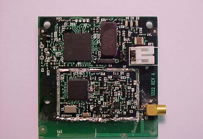
Click to zoom
Application Details
- Equipment Class
- DTS - Digital Transmission System
- Date of Grant
- Jan 03, 2006
- Application Purpose
- Original Equipment
- Date of Application
- Jan 03, 2006
- Equipment Note
- Transceiver Module
- Frequency Range
- 2405.00000000 - 2475.00000000
- Company
- Sensicast Systems, Inc.
- Country
- United States
Documents & Files
Document Text
Text extracted from the exhibit documents filed with the FCC. Open a document above to read the original.
Users Manual
OEM200 MODULE VERSION 1.0 Hardware Manual www.sensicast.com HARDWARE MANUAL OEM200 Module VERSION 1.0 Sensicast Systems, Inc. 220-3 Reservoir Street Needham, MA 02494 Phone 781.453.2555 [email protected] www.sensicast.com Part # 2390 – OEM200 Module Hardware Manual Copyright ©2005 Sensicast Systems, Inc. All rights reserved. Sensicast ® and SensiNet™ are trademarks of Sensicast Systems, Inc. in the United States and/or other countries. All other trademarks are property of their respective owners. In the interest of product improvement, information and specifications herein are subject to change without notice. 2 FCC Statement The A2400 equipment complies with Part 15 of the FCC Rules. Operation is subject to the following two conditions: (1) This device may not cause harmful interference; and (2) This device must accept any interference received, including interference that may cause undesired operation. FCC Caution: Any changes or modifications not expressly approved by Sensicast could void the user’s authority to operate this equipment. FCC RF Radiation Exposure Statement: The module complies with FCC's RF exposure requirements and the module must not be co-located or operated in conjunction with any other antenna or transmitter. FCC Labeling The module is labeled with its own FCC ID number (RNB-OEM200). If this number is not visible when the module is installed inside another device, then the outside of the device into which the module is installed must also display a label with the following wording: “Contains FCC ID:RNB-OEM200” FCC 20cm RF Exposure To comply with FCC’s RF exposure limits for general population / uncontrolled exposure, the antenna(s) used for this transmitter must be installed to provide a separation distance of at least 20 cm from all persons and must not be co-located or operating in conjunction with any other antenna or transmitter. 3 Introduction This design guide is intended to provide a good understanding of the functionality of the OEM200 module. The intended audience is the engineer responsible for integrating the OEM200 into a product. Description and Specifications The OEM200 is a component of the Sensicast A2400 Wireless Sensor Network Platform – a completely self- configuring, self-healing, power managed sensor network. Powered by SensiNet (Sensicast proprietary mesh networking software), the OEM200 is the most reliable mesh networking radio module on the market today. With its external radio amplification stage, it has a range of over 1000 feet (outdoors) and 230 feet (indoors, non-line of site). Furthermore, SensiNet uses frequency diverse radio algorithms to ensue reliable, clear channel communication even in the most harsh radio environments. In addition, off-the-shelf A2400 infrastructure hardware and SensiMesh ® Gateway software for constructing and maintaining your mesh network is available from Sensicast. Block diagram Antenna There is a PCB “Inverted F” antenna on the device. For best performance, care should be taken to keep metal components away from this section of the PCB. The PCB will also support an external antenna connector at J2. However, please note that this product is only FCC certified with the existing embedded antenna. If a user application requires an external antenna, re-submission with the specific external antenna is required for FCC approval. For more details, please contact Sensicast. Radio Transceiver The radio is under control of the OEM200’s microcontroller and is contained inside the metal shield. Microcontroller The SensiNet software, including the sensor API, runs on this microcontroller. It includes onboard flash memory, RAM, and analog and digital I/O and a 32kHz real time clock. LEDs There are three LEDS: red, yellow and green that are firmware controlled. Antenna Radio Transceiver Microcontroller Connector Optional temperature and humidity sensor LEDs 4 Optional temperature and humidity sensor The OEM200 can be preloaded with a temperature and humidity sensor at U7. Please contact Sensicast for temperature and humidity specifications. Connectors The primary interconnection is J1, the 41 position board-to-board, header (Hirose p/n DF9A-41P-1V(20); mates with: Hirose p/n DF9A-41S-1V(20)) on the bottom of the assembly. (Please note that this header is common between the OEM200 and OEM100). Optionally, power can be brought to the board through J3, a two position, right angle wire to board, header (JST p/n S2B-PH-K-S, mate: JST p/n PHR-2). Here is a schematic drawing of J1 and a list of signal descriptions for both connectors: J1 Pin OEM200 Signal OEM200 Description 1 GND Ground 2 GND Ground 3 VCC Power 4 VCC Power J1 CB – J3 (on OEM200) 5 5 GND Ground 6 PD2/RXD1/INT2 [DIG2/EXTINT2] General I/O / External interrupt 7 PC0/SPARE1 General I/O ; end node (OEM200) only 8 PE6/T3/INT6 [DIG1/RTCLK/EXTINT1] Radio Amp Indicator (Tx) – Output 9 PC1/SPARE0 General I/O ; end node (OEM200) only 10 PE5/OC3C/INT5 [DIG0/EXTINT0] General I/O / External interrupt 11 PF1/ADC1 Analog In 12 PD1/SDA/INT1 I2C_DATA 13 PF0/ADC0 Analog In 14 PD6/T1 General I/O / Counter In 15 GND Ground 16 PE2/SCK0/AIN0 RTS 17 RESET# Atmel reset Input 18 PE3/OC3A/AIN1 CTS/16 bit PWM out 19 PF4/ADC4/TCK Module programming 20 PD0/SCL/INT0 I2C_SCK I/O 21 PF5/ADC5/TMS Module programming 22 PC2/SPARE2 General I/O ; end node (OEM200) only 23 PF7/ADC7/TDI Module programming 24 PF7_ATTEN [PIC_ICSPMCLR#] through a 10K resistor / Carrier Board Reset Output 25 PF6/ADC6/TDO Module programming 26 PF6_ATTEN [PIC_ICSPPGM] through a 10K resistor 27 PD7/T2_ATTEN no connect (input through 10K resistor) 28 PE1/TXDO/PD0 UART TX 29 PF5_ATTEN [PIC_ICSPCLK] through a 10K resistor 30 PE0/RXD0/PDI UART RX 31 PD4/ICP1[BOOST_ENABLE] Boost Enable Request Output 32 PF4_ATTEN [PIC_ICSPDAT] through a 10K resistor 33 PD0/SCL/INT0 no connect (bit bang-able SPI) 34 PB4/OC0 Status line/ RS485 Enable 35 PD1/SDA/INT1 no connect (bit bang-able SPI) 36 PE2/SCK0/AIN0 no connect (bit bang-able SPI) 3…
Text truncated - open the document above for the full version.
Cover Letter(s)
~~,~D~!~~ FCCCONFIDENTIALITY Date:03/07/2005Time:14:00EST To:FCCAuthorization&EvaluationDivision 7435OaklandMillsRoad Columbia,MD21045-0429 From:H.JeffGamer VicePresidentofEngineeringandOperations Phone:781-453-2555 Fax:781-453-0601 Applicant:SensicastSystems,Inc.E-Mail:[email protected] Subject:RequestforNondisclosureforFCCID:RNB- OEM200. ToWhomIt MayConcern: Pursuantto47CFRSection0.459,SensicastSystems,Inc.herebyrequestsnondisclosureand confidentialtreatmentofthefollowingmaterialssubmittedinsupportofFCCcertification applicationforFCCID# RNB-OEM200. a.SchematicDiagrams b.OperationalDescription c.BlockDiagram Abovematerialscontaintradesecrets,proprietaryandtechnicalinformationwhichwould customarilybeguardedITomcompetitorsunder47CFRsection0.457(d)(2).Disclosureor publicationofanyportionofthiscompanyconfidentialmaterialtootherpartiescouldcause substantialcompetitiveharmandprovideunjustifiedbenefitsforcompetitors. SensicastSystems,Inc.understandsthatpursuantto47CFRsection0.457(d)(I)(ii)disclosure oftheapplicantandallaccompanyingdocumentationwillnotbemadebeforethedateofthe grant. SensicastSystems,Inc. 220-3ReservoirSt. Needham,MA02494 :!9if~ VicePresidentEngineeringandOperations SensicastSystems,Inc. P:781.453.2555 F:781.453.0601 http://www.sensicast.com *
Cover Letter(s)
Question: The modular approval request letter states that above 3.6V, the unit would refuse to transmit. Pg 25 of the report shows RF output power measurements at 3.8V. Please clarify. Response: The unit provided for testing did not have the production version of software. The software monitoring of the voltage regulation was not present in the test code used. The production units have a high voltage shutdown level set at 3.6V. Please note that the 3.8V measurement on page 25 of the test report was at the +15% variation limit.
Cover Letter(s)
.~,§D~!~~ FCCAuthorization Date:March7, 2005 Time:14:00EST To:FCCAuthorization&EvaluationDivision 7435OaklandMillsRoad Columbia,MD21045-0429 From:H.JeffGamer VicePresidentofEngineeringandOperations Phone:781-453-2555 Fax:781-453-0601 Applicant:SensicastSystems,Inc. E-Mail:[email protected] DearLadiesand/orGentlemen: I appointKennethL.Boston,JamesBlahaandTeresaWhiteatL.S.Compliance,Inc.,toactas anagentinthepreparationofapplicationsunderPart15oftherulesandregulationsofthe FederalCommunicationsCommission.I certifythattheexhibitionsproperlydescribethe devicebeingsubmittedunderthisapplicationandwillimplementanychangesdescribedinthe testreport.Thelabelsdescribedwillbeaffixedtoeachitem. Thefollowingstatementis requiredbytheFederalCommunicationsCommission:Bychecking Yes,theapplicantcertifiesthat,inthecaseofanindividualapplicant,heorsheis notsubjectto a denialoffederalbenefits,thatincludedFCCbenefits,pursuanttosection5301oftheAnti- DrugAbuseActof1988,21U.S.C853(a),or,inthecaseofa non-individualapplicant(e.g. corporation,partnership,orotherunincorporatedassociation),nopartytotheapplicationis subjecttoa denialoffederalbenefits,thatincludesFCCbenefits,pursuanttothatsection. xYesNo -- ~rtll7i~~ H.JeffGamer VicePresidentofEngineeringandOperations SensicastSystems,Inc. 220-3ReservoirSt. Needham,MA02494 P:781.453.2555 F:781.453.0601 http://www.sensicast.com ~
External Photos
Sensicast Systems, Inc. OEM Node 2400 – 2483 MHz FCC ID: RNB-OEM200 Photo One – External PCB Module of OEM Node Sensicast Systems, Inc. OEM Node 2400 – 2483 MHz FCC ID: RNB-OEM200 Photo Two – External Close-Up of FCC ID Label
ID Label/Location Info
Trademarks - Copyrights© - Warranties - Returns Home | Inkjet Prices | Laser Prices | Order Form | FAQ | Tech Support | Samples | Contact Us Inkjet Labels. Laser Labels. Waterproof Labels. Any Size, Any Shape. No Die Charge on Short Run Jobs. Laser Cardstock. Inkjet Cardstock. Waterproof Paper. Dozens of Materials. Laser 102250 Outdoor Indoor White Polyester Perm Product Information Description: This label features a standard pressure construction including a 2 mil laser-print a polyester facestock that has excellent he resistance and dimensional stability. Thi features a specialty moderately aggres s removable adhesive that shows good in high shear strength, high removable str e excellent clarity. The clay-coated kraft li been coated one side to give a controlle Facestock 2 mil white top-coated polyester with a very smooth matte finish. It has e tear strength, heat resistance and dimensional stability while the top-coat excellent laser toner receptivity. Caliper 2 mil Opacity 75% Adhesive Clear acrylic adhesive featuring good removability on a wide range of su including corrugated and many plastic surfaces. Coat weight 1.0 cwt Min. application temp: +40 F Indirect Food: Yes Min. service temp: -65 F Direct Food: No Max. service temp: +150 F UL Approved: Ye s Note: For best bonding conditions, application surface should be at room ature or higher. Low temperature surfaces, below +40F can cause the ad become so firm that it will not develop maximum contact with the substra initial bonds can be achieved through increased rubdown pressure. In o a true measure of the adhesive’s effectiveness, the label should be appli allowed to bond a minimum of 24 hours prior to evaluation. Liner Clay-coated lay-flat liner which has been silicone coated one side to give controlled release. Caliper: 4.5 mils Weight: 74# The above are typical technical values and are given in good faith based upon our most u p knowledge and experience. As the products are used outside our control we cannot take responsibility for any damage that may be caused using the product. In every case, user s determine before using any product in full-scale production, or in any way, whether such pr suitable for user’s intended use for their particular purpose under their own operating condi Home | Inkjet Prices | Laser Prices | Order Form | FAQ | Tech Support | Samples | Contact Us Page 1 of 2102250 Outdoor Indoor White Polyester Perm 3/8/2005http://www.rippedsheets.com/laser/info/102250.html Rippedsheets.com Site Index Page 2 of 2102250 Outdoor Indoor White Polyester Perm 3/8/2005http://www.rippedsheets.com/laser/info/102250.html
ID Label/Location Info
Sensicast Systems, Inc. Model : O EM200 FCC ID: RNB-OEM200 This device complies with Part 15 of the FCC rules. Operation is subject to the following two conditions: (1) this device may not cause harmful interference, and (2) this device must accept any interference received, including interference that may caus e undes i red operat i on.
Internal Photos
Sensicast Systems, Inc. OEM Node 2400 – 2483 MHz FCC ID: RNB-OEM200 Photo One – Internal Shield Removed for Inspection Sensicast Systems, Inc. OEM Node 2400 – 2483 MHz FCC ID: RNB-OEM200 Photo Two – Internal RF Section Close-Up Sensicast Systems, Inc. OEM Node 2400 – 2483 MHz FCC ID: RNB-OEM200 Photo Three – Internal PCB Flip Side Sensicast Systems, Inc. OEM Node 2400 – 2483 MHz FCC ID: RNB-OEM200 Photo Four – Internal PCB Antenna Close-Up
RF Exposure Info
Prediction of MPE limit at a given distance Equation from page 18 of OET Bulletin 65, Edition 97-01 where:S = power density P = power input to the antenna G = power gain of the antenna in the direction of interest relative to an isotropic radiator R = distance to the center of radiation of the antenna Maximum peak output power at the antenna terminal:15.30(dBm) Maximum peak output power at the antenna terminal:33.88441561(mW) Antenna gain(typical):0(dBi) Maximum antenna gain:1(numeric) Prediction distance:20(cm) Prediction frequency:2450(MHz) MPE limit for uncontrolled exposure at prediction frequency:1(mW/cm^2) Power densit y at prediction frequency:0.006741(mW/cm^2) Maximum allowable antenna gain:21.71269855(dBi) 2 4R PG S π =
Test Report
L.S. Compliance, Inc. W66 N220 Commerce Court Cedarburg, WI 53012 262-375-4400 Fax: 262-375-4248 COMPLIANCE TESTING OF: OEM 200 2.4 GHz Module PREPARED FOR: Sensicast Systems Attn.: Mr. Jay Werb 220-3 Reservoir Street Needham, MA 02494 TEST REPORT NUMBER: 304365-TCB-v1 TEST DATE(S) : February 4 th , 7 th , 15 th , 18 th and March 2 nd , 2005 All results of this report relate only to the items that were tested. This report is not to be reproduced, except in full, without written approval of L. S. Compliance, Inc. L.S. Compliance, Inc. Page 2 of 42 Test Report Number: 304365-TCB-v1 Prepared For: Sensicast Systems Table of Contents Section Description Page Index 2 1 L. S. Compliance in Review 3 2 A2LA Certificate of Accreditation 4 3 A2LA Scope of Accreditation 5 4 Validation Letter-U.S. Competent Body for EMC Directive 89/336/EEC 6 5 Signature Page 7 6 Product and General Information 8 7 Introduction 8 8 Product Description 8 9 Test Requirements 9 10 Summary of Test Report 9 11 Radiated Emissions Test 10-20 12 Conducted Emissions Test, AC Power Line 21-24 13 Conducted Emissions Test, Power Output 25-26 14 Conducted Emissions Test, Spurious Emissions 27-30 15 Conducted Emissions Test, Occupied Bandwidth 31-33 16 Conducted Emissions Test, Spectral Density 34-36 Appendix A Test Equipment List 37 B Additional Test Information 38-42 L.S. Compliance, Inc. Page 3 of 42 Test Report Number: 304365-TCB-v1 Prepared For: Sensicast Systems 1. L. S. Compliance In Review L.S. Compliance - Accreditations and Listing’s As an EMC Testing Laboratory, our Accreditation and Assessments are recognized through the following: A2LA – American Association for Laboratory Accreditation Accreditation based on ISO/IEC 17025 : 1999 with Electrical (EMC) Scope of Accreditation A2LA Certificate Number: 1255.01 Federal Communications Commission (FCC) – USA Listing of 3 Meter Semi-Anechoic Chamber based on Title 47 CFR – Part 2.948 FCC Registration Number: 90756 Listing of 3 and 10 meter OATS based on Title 47CFR – Part 2.948 FCC Registration Number: 90757 Industry Canada On file, 3 Meter Semi-Anechoic Chamber based on RSS-212 – Issue 1 File Number: IC 3088-A On file, 3 and 10 Meter OATS based on RSS-212 – Issue 1 File Number: IC 3088 U. S. Conformity Assessment Body (CAB) Validation Validated by the European Commission as a U. S. Competent Body operating under the U. S. /EU, Mutual Recognition Agreement (MRA) operating under the European Union Electromagnetic Compatibility –Council Directive 89/336/EEC, Article 10.2. Date of Validation: January 16, 2001 Validated by the European Commission as a U.S. Notified Body operating under the U.S./EU, Mutual Recognition Agreement (MRA) operating under the European Union Telecommunication Equipment – Council Directive 99/5/EC, Annex V. Date of Validation: November 20, 2002 Notified Body Identification Number: 1243 L.S. Compliance, Inc. Page 4 of 42 Test Report Number: 304365-TCB-v1 Prepared For: Sensicast Systems 2. A2LA Certificate L.S. Compliance, Inc. Page 5 of 42 Test Report Number: 304365-TCB-v1 Prepared For: Sensicast Systems 3. Scope of Accreditation L.S. Compliance, Inc. Page 6 of 42 Test Report Number: 304365-TCB-v1 Prepared For: Sensicast Systems 4. Validation Letter – U.S. Competent Body for EMC Directive 89/336/EEC L.S. Compliance, Inc. Page 7 of 42 Test Report Number: 304365-TCB-v1 Prepared For: Sensicast Systems 5. Signature Page Prepared By: December 28, 2005 Teresa A. White, Document Coordinator Date Tested and Approved By: December 28, 2005 Kenneth L. Boston, EMC Lab Manager Date PE #31926 Licensed Professional Engineer Registered in the State of Wisconsin, United States L.S. Compliance, Inc. Page 8 of 42 Test Report Number: 304365-TCB-v1 Prepared For: Sensicast Systems 6. Product and General Information Manufacturer: Sensicast Systems Date(s) of Test: Feb. 4 th , 7 th , 18 th and Mar. 2 nd , 2005 Test Engineer(s): Tom Smith Abtin Spantman √ Ken Boston Model #: OEM 200 Serial #: Engineering Unit Voltage: 3.3 VDC Operation Mode: Continuous modulated transmit on channels 0,7 and 14 7. Introduction During February and March, 2005 a series of Conducted and Radiated Emission tests were performed on one sample of the Sensicast Systems OEM 200, here forth referred to as the “Equipment Under Test” or “EUT”. These tests were performed using the procedures outlined in ANSI C63.4-2003 for intentional radiators, and in accordance with the limits set forth in FCC Part 15.109 (Industry Canada RSS-210) for a receiver or digital device. These tests were performed by Kenneth L. Boston, EMC Lab Manager, of L.S. Compliance, Inc. All Radiated and Conducted Emission tests upon the EUT were performed to measure the emissions in the frequency bands described in Title 47 CFR, FCC Part 15, including 15.35, 15.247, 15.109a and Industry Canada RSS-210 to determine whether these emissions are below the limits expressed within the standards. These tests were performed in accordance with the procedure described in the American National Standard for methods of measurement of Radio-Noise Emissions from Low-Voltage Electrical and Electronic Equipment in the Range of 9 kHz to 40 GHz (ANSI C63.4-2003). Another document used as a reference for the EMI Receiver specification was the Comite International Special Des Perturbations Radioelelectriques CISPR 16-1, 2003. All tests were performed at L.S. Compliance, Inc. in Cedarburg, Wisconsin, unless otherwise noted. 8. Product Description The OEM200 End Node is a battery-operated, 2400MHz transceiver that can wirelessly transmit and receive data to and from A2400 Coordinator devices. It is not a routing device. The OEM200 will require a power source to operate (typically a battery) and a sensor and/or actuator to be useful. The device can measure and report temperature and humidity using and onboard sensor but typically the OEM200 will be plugged into a mating receptacle on a carrier board. This carrier board will house a sensor and/or actuator, a power sou…
Text truncated - open the document above for the full version.
Test Setup Photos
Photos Taken During Radiated Emission Testing OEM200 Sensicast Setup for the Radiated Emissions Test, Vertical Position Setup for the Radiated Emissions Test, Horizontal Position Setup for the Radiated Emissions Test, Side Position Test Setup for the Conducted RF Measurements
Contact Information
Applicant
John OBrien
Test Firm
LS Research, LLCRyan Urness
Technical Specifications
| # | Rule Parts | Frequency Range | Power Output |
|---|---|---|---|
| 1 | 15C | 2.40 GHz - 2.48 GHz | 34.00 mW |
Other Applications from Sensicast Systems, Inc.
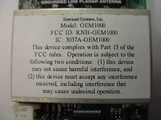
RNB-OEM1000
Feb 26, 2007Transceiver Module
Equipment Class
DSS - Part 15 Spread Spectrum Transmitter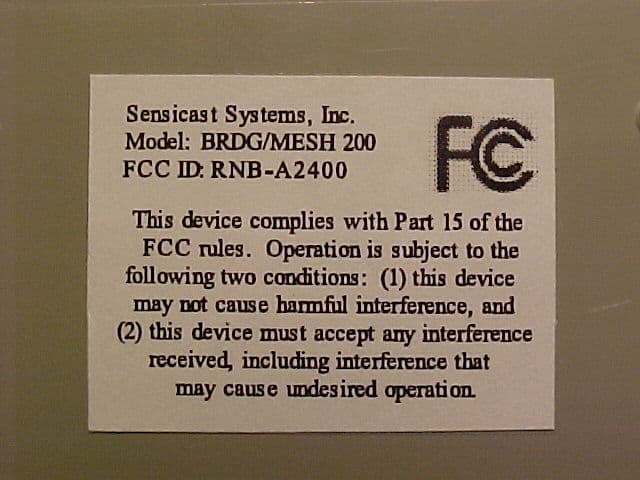
RNB-A2400
Jan 03, 2006Networking Device
Equipment Class
DTS - Digital Transmission System
RNB-OEM100
Dec 19, 2004Networking Transceiver Module
Equipment Class
DSS - Part 15 Spread Spectrum Transmitter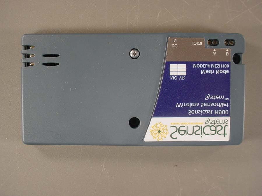
RNBF19D8MN9LQ2WFA
Dec 08, 2003Spread Spectrum Transmitter
Equipment Class
DSS - Part 15 Spread Spectrum Transmitter