RNB-OEM1000Transceiver Module
Sensicast Systems, Inc.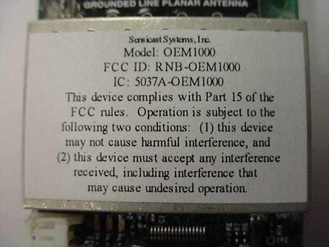
Click to zoom
Application Details
- Equipment Class
- DSS - Part 15 Spread Spectrum Transmitter
- Date of Grant
- Feb 26, 2007
- Application Purpose
- Original Equipment
- Date of Application
- Feb 26, 2007
- Equipment Note
- Transceiver Module
- Frequency Range
- 902.50000000 - 925.80000000
- Company
- Sensicast Systems, Inc.
- Country
- United States
Documents & Files
Document Text
Text extracted from the exhibit documents filed with the FCC. Open a document above to read the original.
Users Manual
OEM100 AND OEM1000 MODULES VERSION 1.5 Hardware Manual www.sensicast.com HARDWARE MANUAL OEM100 and OEM1000 Modules VERSION 1.5 Sensicast Systems, Inc. 220-3 Reservoir Street Needham, MA 02494 Phone 781.453.2555 [email protected] www.sensicast.com Part # 1390 – OEM100 and OEM1000 Module Hardware Manual Copyright ©2006 Sensicast Systems, Inc. All rights reserved. Sensicast and SensiNet are trademarks of Sensicast Systems, Inc. in the United States and/or other countries. All other trademarks are property of their respective owners. In the interest of product improvement, information and specifications herein are subject to change without notice. 2 FCC Statement The OEM100 and OEM1000 equipment complies with Part 15 of the FCC Rules. Operation is subject to the following two conditions: (1) This device may not cause harmful interference; and (2) This device must accept any interference received, including interference that may cause undesired operation. FCC Caution: Any changes or modifications not expressly approved by Sensicast could void the user’s authority to operate this equipment. FCC RF Radiation Exposure Statement: To comply with FCC’s RF exposure limits for general population/uncontrolled exposure, the antenna(s) used for this transmitter must be installed to provide a separation distance of 20 cm from all persons and must not be co-located or operated in conjunction with any other antenna or transmitter. FCC Labeling The module is labeled with its own FCC ID number (RNB-OEM100 or RNB-OEM1000). If this number is not visible when the module is installed inside another device, then the outside of the device into which the module is installed must also display a label with the following wording: “Contains FCC ID:RNB-OEM100” or “Contains FCC ID:RNB-OEM1000” OEM Responsibility to the FCC Rules and Regulations The OEM100 and OEM1000 modules have been certified per FCC part 15 rules for integration into products without further testing or certification. To fulfill the FCC certification requirements the OEM using the OEM100 or OEM1000 module must ensure that the information provided on the OEM100 or OEM1000 Lavel is placed on the outside of the final product. The OEM100 or OEM1000 module is labeled with its own FCC ID number (RNB-OEM100 or RNB-OEM1000). If this FCC ID number is not visible when the module is installed inside another device, then the outside of the device into which the module is installed must also display a label with the following wording: “Contains FCC ID:RNB-OEM100” or “Contains FCC ID:RNB- OEM1000”. The OEM of the OEM100 or OEM1000 Module must only use the approved antenna, which has been certified with this module. The OEM of the OEM100 or OEM1000 Module must test their final product configuration to comply with Unintentional Radiator Limits before declaring FCC compliance per part 15 of the FCC rules. Industry Canada Statement per Section 4.0 of RSP-100 The term IC: before the certification / registration number only signifies that Industry Canada technical specifications were met. Section 7.1.5 of RSS-GEN Operation is subject to the following two conditions: 1) this device may not cause harmful interference, and 2) this device must accept any interference received, including interference that may cause undesired operation. Section 2.6 of RSS-102 This mobile transmitter with its antenna complies with Industry Canada RF Exposure Limits for General Population / Uncontrolled Exposure. 3 Introduction This design guide is intended to provide a good understanding of the functionality of the OEM100 or OEM1000 module. The intended audience is the engineer responsible for integrating the OEM module into a product. Description and Specifications The OEM100 or OEM1000 is a component of the Sensicast H900 Wireless Sensor Network Platform – a completely self-configuring, self-healing, power managed sensor network. Powered by SensiNet, Sensicast’s proprietary mesh networking software, the OEM100/OEM1000 is the most reliable mesh networking radio module on the market today. It has a range of over 1000 feet (outdoors) (1 mile OEM1000) and 300 feet (indoors, non-line of site) (1000 feet OEM1000). Furthermore, SensiNet uses frequency diverse radio algorithms to ensue reliable, clear channel communication even in the most harsh radio environments. In addition, off-the-shelf H900 infrastructure hardware and software for constructing and maintaining your mesh network is available from Sensicast. Block diagram Antenna There is a board mounted antenna on the device. For best performance, care should be taken to keep metal components away from the antenna. Radio Transceiver The radio is under control of the OEM100/OEM1000’s microcontroller and is contained inside the metal shield. Microcontroller The SensiNet software, including the sensor API, runs on this microcontroller. It includes onboard flash memory, RAM, and analog and digital I/O and a 32Khz real time clock. LEDs There are three LEDS: red, yellow and green that are firmware controlled. Optional temperature and humidity sensor Antenna Radio Transceiver Microcontroller Connectors Optional temperature and humidity sensor LEDs 4 The OEM100/OEM1000 can be preloaded with a temperature and humidity sensor. Please contact Sensicast for temperature and humidity specifications. Connectors The primary interconnection is P3, the 41 position board to board, header (Hirose p/n DF9A-41P-1V(20); mates with: Hirose p/n DF9A-41S-1V(20)) on the bottom of the assembly. Optionally, power can be brought to the board through P5, a two position, right angle wire to board, header (JST p/n S2B-PH-K-S, mate: JST p/n PHR-2). Here is a schematic drawing of P3 and a list of signal descriptions for both connectors: J3 Pin OEM module Signal Type OEM module Description 1 GND Ground Ground 2 GND Ground Ground 3 VCC Power Power 4 VCC Power Power 5 GND Ground Ground 6 DIG2/EXTINT2 I/O General I/O / external interrupt 7 SPARE1 I/O General I/O 8 DIG1/EXTINT1 I/O…
Text truncated - open the document above for the full version.
Cover Letter(s)
.~,§D~!~~ FCCAuthorization Date:March7, 2005 Time:14:00EST To:FCCAuthorization&EvaluationDivision 7435OaklandMillsRoad Columbia,MD21045-0429 From:H.JeffGamer VicePresidentofEngineeringandOperations Phone:781-453-2555 Fax:781-453-0601 Applicant:SensicastSystems,Inc. E-Mail:[email protected] DearLadiesand/orGentlemen: I appointKennethL.Boston,JamesBlahaandTeresaWhiteatL.S.Compliance,Inc.,toactas anagentinthepreparationofapplicationsunderPart15oftherulesandregulationsofthe FederalCommunicationsCommission.I certifythattheexhibitionsproperlydescribethe devicebeingsubmittedunderthisapplicationandwillimplementanychangesdescribedinthe testreport.Thelabelsdescribedwillbeaffixedtoeachitem. Thefollowingstatementis requiredbytheFederalCommunicationsCommission:Bychecking Yes,theapplicantcertifiesthat,inthecaseofanindividualapplicant,heorsheis notsubjectto a denialoffederalbenefits,thatincludedFCCbenefits,pursuanttosection5301oftheAnti- DrugAbuseActof1988,21U.S.C853(a),or,inthecaseofa non-individualapplicant(e.g. corporation,partnership,orotherunincorporatedassociation),nopartytotheapplicationis subjecttoa denialoffederalbenefits,thatincludesFCCbenefits,pursuanttothatsection. xYesNo -- ~rtll7i~~ H.JeffGamer VicePresidentofEngineeringandOperations SensicastSystems,Inc. 220-3ReservoirSt. Needham,MA02494 P:781.453.2555 F:781.453.0601 http://www.sensicast.com ~
Cover Letter(s)
Polar Plots and VSWR Graph Antenna Factor575 S.E. Ashley Place Grants Pass, OR 97526-3237 www.antennafactor.com 541-956-0931 (phone) 541-471-6251 (fax) Rev 07-20-06 Typical VSWR ANT-916-SP DATA SHEETS Product DimensionsDescription Features Electrical Specifications Ordering Information AzimuthElevation -30.0 -20.0 -10.0 0.0 10.0 -30.0 -20.0 -10.0 0.0 10.0 The Splatch uses a grounded-line technique to achieve outstanding performance from a tiny surface-mount element. This unique antenna is designed for hand or reflow mounting directly to a product’s circuit board. Its low cost makes it ideal for volume applications. Unlike many compact antennas, the Splatch exhibits good proximity performance, making it an appropriate choice for hand-held applications such as remote controls, pagers, and alert devices. Typical performance is below that of some external antennas, but the Splatch is an excellent choice when cosmetic or mechanical issues dictate the use of an internal antenna. Very low cost Ultra-compact package Ideal for concealed / internal mounting Perfect for compact portable devices Suitable for hand or reflow assembly Resistant to proximity effect Direct PCB attachment Center Freq. Bandwidth Wavelength VSWR Impedance Gain Connection 916MHz 30MHz 1/4-wave <1.9 typ. at center 50 ohms TBD Surface-mount Note: Electrical specifications and plots measured on a 1.50” x 3.30” ground plane ANT-916-SP (supplied in tubes of 20 pcs.) 0.54” (13.7) 0.20” (5.1) 0.06” (1.5) 1.12” (28.4) No ground plane or traces under the antenna Ground plane on bottom layer for counterpoise 50-ohm microstrip line Vias to ground plane 1 1 GROUNDED LINE PLANAR ANTENNA 916-SP PCB pads for the Splatch 1.50" x 3.30" recommended ground plane CENTER 916.000MHz SPAN 75.000MHz S11 SWR 1.328 -50.0 -40.0 -30.0 -20.0 -10.0 0.0 Coming Soon Coming Soon PCB Footprint 0.20” (5.1) 0.10” (2.5) 0.08” (2.0) Antenna Factor575 S.E. Ashley Place Grants Pass, OR 97526-3237 www.antennafactor.com 541-956-0931 (phone) 541-471-6251 (fax) ANT-916-SP DATA SHEETS Azimuth Radiation Pattern Elevation Radiation Pattern Antenna Test Fixture 1.50” (38.1) 3.30” (83.8) 0.56” (14.2) SHADED AREA INDICATES GROUND PLANE ON BOTTOM LAYER NO GROUND PLANE OR COMPONENTS (EXCEPT ANTENNA) IN WHITE AREA The adjoining diagram shows the dimensions of the fixture on which the stated pattern and gain measurements were made. This does not mean that your product must conform to this size or antenna orientation, although it should be recognized that the gain, pattern, and performance may increase or decrease accordingly. Antenna Factor recognizes that our antennas are often used in compact applications with less than ideal ground planes. In some cases, the reference jig is smaller than optimum, particularly with lower-frequency antennas. This is, in part, to more accurately reflect the performance of the antenna in typical real-world applications. ABOUT THIS TEST FIXTURE Gain of AUT -30.0 -20.0 -10.0 0.0 10.0 Gain of AUT -30.0 -20.0 -10.0 0.0 10.0 Measurement Antenna Polarity: Vertical Test Antenna Polarity: Perpendicular Maximum Absolute Gain: -0.99dBi Measurement Antenna Polarity: Horizontal Test Antenna Polarity: Horizontal Maximum Absolute Gain: TBD -50.0 -40.0 -30.0 -20.0 -10.0 0.0 0 Coming Soon Coming Soon LS Research, LLC Prepared For: Sensicast Systems Template: 15.247 FHSS TX (V1 6-28-06) Report #: 306159 TX Customer FCC ID #: RNB-OEM1000 Page 48 of 48 From: Justin Hopper [[email protected]] Sent: Tuesday, March 14, 2006 5:02 PM To: Abtin Spantman Subject: RE: Ant Gain for projects 305440 and 306159 Hello, Peak gain of this one will be 2.5dBi. Support Linx Technologies 575 S.E. Ashley Place Grants Pass, OR, 97526 USA [email protected] www.linxtechnologies.com Phone: 1-800-736-6677 Fax: 541-471-6251 From: Abtin Spantman [mailto:[email protected]] Sent: Tuesday, March 07, 2006 6:02 PM To: Justin Hopper Subject: FW: Ant Gain for projects 305440 and 306159 Hi Justin: OK I lied. That is not all I needed. I just got another project with another antenna that I need a gain declaration for: “ANT-916-SP” before I can file with the FCC. It will be the middle of next week before I will need this information, as I am not finished testing this product yet. If I can impose on you to declare a gain figure for the Splatch, at your leisure, I would appreciate your efforts on our behalf. Thank you again. Best regards, Abtin Spantman RF / EMC Engineer L.S. Compliance, Incorporated W66 N220 Commerce Court Cedarburg, WI 53012 U.S.A. Direct: 262.421.4992 Main: 262.375.4400 Fax: 262.364.2649 Email: [email protected] Visit us on the web: www.lsr.com
Cover Letter(s)
File:Modular Cover Letter CONFIDENTIAL Page 1 of 1 July 24, 2006 Re: Modular Transmitter Approval FCC ID: RNB-OEM1000 Gentlemen, The following information is being provided per the requirements of DA00-1407 regarding modular approval of Part 15 devices. This transceiver is a complete RF module with an integral reference oscillator. External connections are provided for power and data communication. The following numbered items correspond to similarly numbered paragraphs in DA00-1407. Each item is a response to the requirements of that document. 1) The module has integral RF shielding to isolate it from surrounding equipment and the larger environment in general. 2) All inputs are processed as data by the on-board microcontroller. The outside user has no direct control of transmit modulation. 3) The microcontroller monitors the amplifier power supply voltage on a continuous basis. Should the supply voltage be found to be greater than the specified maximum of 3.6 volts the unit will refuse to transmit. 4) An on board antenna is used with this module. This is in accordance with Part 15.203. 5) The module was tested in a stand-alone configuration and found to be compliant with Part 15 regulations. 6) An FCC ID label is affixed to each unit at the time of manufacture. Information is also clearly presented in the user guide about labeling requirements for the final assembly. 7) This unit is compliant with Part 15.247. Installation and other requirements are presented in the user guide to allow the unit to be correctly installed. 8) The unit is compliant with the RF exposure requirements of Parts 15.247, 15.1091, and 15.1093. Further information may be obtained from LS Research, LLC. Sincerely, James Blaha
External Photos
Sensicast Systems OEM 1000 FCC ID#: RNB-OEM1000 Photo One – External Front View, showing FCC ID Label Sensicast Systems OEM 1000 FCC ID#: RNB-OEM1000 Photo Two – External Close up of FCC ID Label
ID Label/Location Info
Sensicast Systems, I nc. Model: OEM1000 F C C ID : R N B -O EM1000 IC : 5037A -O EM1000 This device complies with Part 15 of the FCC rules. Operation is subject to the following two conditions: (1) this device may not cause harmful interference, and (2) this device must accept any interference received, including interference that may caus e undes i red operat i on.
ID Label/Location Info
Trademarks - Copyrights© - Warranties - Returns Home | Inkjet Prices | Laser Prices | Order Form | FAQ | Tech Support | Samples | Contact Us Inkjet Labels. Laser Labels. Waterproof Labels. Any Size, Any Shape. No Die Charge on Short Run Jobs. Laser Cardstock. Inkjet Cardstock. Waterproof Paper. Dozens of Materials. Laser 102250 Outdoor Indoor White Polyester Perm Product Information Description: This label features a standard pressure construction including a 2 mil laser-print a polyester facestock that has excellent he resistance and dimensional stability. Thi features a specialty moderately aggres s removable adhesive that shows good in high shear strength, high removable str e excellent clarity. The clay-coated kraft li been coated one side to give a controlle Facestock 2 mil white top-coated polyester with a very smooth matte finish. It has e tear strength, heat resistance and dimensional stability while the top-coat excellent laser toner receptivity. Caliper 2 mil Opacity 75% Adhesive Clear acrylic adhesive featuring good removability on a wide range of su including corrugated and many plastic surfaces. Coat weight 1.0 cwt Min. application temp: +40 F Indirect Food: Yes Min. service temp: -65 F Direct Food: No Max. service temp: +150 F UL Approved: Ye s Note: For best bonding conditions, application surface should be at room ature or higher. Low temperature surfaces, below +40F can cause the ad become so firm that it will not develop maximum contact with the substra initial bonds can be achieved through increased rubdown pressure. In o a true measure of the adhesive’s effectiveness, the label should be appli allowed to bond a minimum of 24 hours prior to evaluation. Liner Clay-coated lay-flat liner which has been silicone coated one side to give controlled release. Caliper: 4.5 mils Weight: 74# The above are typical technical values and are given in good faith based upon our most u p knowledge and experience. As the products are used outside our control we cannot take responsibility for any damage that may be caused using the product. In every case, user s determine before using any product in full-scale production, or in any way, whether such pr suitable for user’s intended use for their particular purpose under their own operating condi Home | Inkjet Prices | Laser Prices | Order Form | FAQ | Tech Support | Samples | Contact Us Page 1 of 2102250 Outdoor Indoor White Polyester Perm 3/8/2005http://www.rippedsheets.com/laser/info/102250.html Rippedsheets.com Site Index Page 2 of 2102250 Outdoor Indoor White Polyester Perm 3/8/2005http://www.rippedsheets.com/laser/info/102250.html
Internal Photos
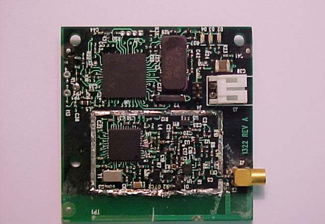
Sensicast Systems OEM 1000 FCC ID#: RNB-OEM1000 Photo One – Internal Open for Inspection Sensicast Systems OEM 1000 FCC ID#: RNB-OEM1000 Photo Two – Internal Close up of RF Section Sensicast Systems OEM 1000 FCC ID#: RNB-OEM1000 Photo Three – Internal Surface Mount Antenna Sensicast Systems OEM 1000 FCC ID#: RNB-OEM1000 Photo Four – Internal Flip Side of RF Board
RF Exposure Info
LS Research, LLC Prepared For: Sensicast Systems Template: 15.247 FHSS TX (V1 6-28-06) Report #: 306159 TX Customer FCC ID #: RNB-OEM1000 Page 45 of 47 EXHIBIT 16. MPE CALCULATIONS Antenna Manufacturer: Antenna Factor Model Number: ANT-916-SP Declared Antenna Gain: 2.5 dBi Prediction of MPE limit at a given distance Equation from page 18 of OET Bulletin 65, Edition 97-01 where:S = power density P = power input to the antenna G = power gain of the antenna in the direction of interest relative to an isotropic radiator R = distance to the center of radiation of the antenna Maximum peak output power at antenna input terminal:28.90 (dBm) Maximum peak output power at antenna input terminal:776.247 (mW) Antenna gain(typical):2.5(dBi) Maximum antenna gain:1.778(numeric) Prediction distance:20(cm) Prediction frequency:915(MHz) MPE limit for uncontrolled exposure at prediction frequency:0.62(mW/cm^2) Power density at prediction frequency:0.274619(mW/cm^2) Maximum allowable antenna gain:6.0 (dBi) 20cm =3.5 dB Margin of Compliance at 2 4R PG S π =
Test Report
LS Research, LLC W66 N220 Commerce Court ● Cedarburg, WI 53012 ● USA Phone: 262.375.4400 ● Fax: 262.375.4248 www.lsr.com LS Research, LLC Prepared For: Sensicast Systems Report #:306159 TX Customer FCC ID #: RNB-OEM1000 Page 1 of 47 ENGINEERING TEST REPORT # 306159-TX-v1 Compliance Testing of: Sensicast OEM-1000 Test Date(s): February 27 TH , through May 31 ST , 2006 Prepared For: Sensicast Systems Incorporated 220-3 Reservoir Street Needham, MA 02494 U.S.A. In accordance with: Federal Communications Commission (FCC) Part 15, Subpart C, Section 15.247 FHSS TX Frequency Hopping Spread Spectrum Operating in the Frequency Band 902 MHz – 928 MHz This Test Report is issued under the Authority of: Brian E. Petted, VP of Engineering Signature: Date: August 4, 2006 Test Report Prepared by: Teresa A. White, Document Coordinator Signature: Date: August 4, 2006 Tested by: Abtin Spantman, RF / EMC Engineer Signature: Date: August 4, 2006 This Test Report may not be reproduced, except in full, without written approval of LS Research, LLC. LS Research, LLC Prepared For: Sensicast Systems Template: 15.247 FHSS TX (V1 6-28-06) Report #: 306159 TX Customer FCC ID #: RNB-OEM1000 Page 2 of 47 TABLE OF CONTENTS (page 1 of 2) EXHIBIT 1. INTRODUCTION 4 1.1 Scope 4 1.2 Normative References 4 1.3 LS Research, LLC Test Facility 5 1.4 Location of Testing 5 1.5 Test Equipment Utilized 5 EXHIBIT 2. PERFORMANCE ASSESSMENT 6 2.1 Client Information 6 2.2 Equipment Under Test (EUT) Information 6 2.3 Associated Antenna Description 6 2.4 EUT’s Technical Specifications 7 2.5 Product Description 8 EXHIBIT 3. EUT OPERATING CONDITIONS & CONFIGURATIONS DURING TESTS 9 3.1 Climate Test Conditions 9 3.2 Applicability & Summary of EMC Emission Test Results 9 3.3 Modifications Incorporated in the EUT for Compliance Purposes 9 3.4 Deviations & Exclusions from Test Specifications 9 3.5 Test Specifications and Related Documents 10 EXHIBIT 4. DECLARATION OF CONFORMITY 11 EXHIBIT 5. RADIATED EMISSIONS TEST 12 5.1 Test Setup 12 5.2 Test Procedure 12 5.3 Test Equipment Utilized 13 5.4 Test Equipment List 13 5.5 Test Results 13 5.6 Calculation of Radiated Emission Measurements 14 5.7 Radiated Emissions Test Data Chart 15-16 5.8 Test Setup Photo(s)-Radiated Emissions Test 17-18 5.9 Screen Captures-Radiated Emissions Testing 19-22 EXHIBIT 6. CONDUCTED EMISSIONS TEST, AC POWER LINE: 15.207 23 6.1 Test Setup 21 6.2 Test Procedure 21 6.3 Test Equipment Utilized 21 6.4 Test Equipment List 23 6.5 Test Results 23 6.6 FCC Limits of Conducted Emissions at the AC Mains Ports 24 6.7 Conducted Emissions Test Data Chart 25 6.8 Test Setup Photo(s)-Conducted Emissions Test 26 6.9 Screen Captures-Conducted Emissions Test 27 LS Research, LLC Prepared For: Sensicast Systems Template: 15.247 FHSS TX (V1 6-28-06) Report #: 306159 TX Customer FCC ID #: RNB-OEM1000 Page 3 of 47 TABLE OF CONTENTS (page 2 of 2) EXHIBIT 7. OCCUPIED BANDWIDTH; 15.247(a)(2) 28 7.1 Limits 28 7.2 Method of Measurements 28 7.3 Test Data 28 7.4 Test Equipment List 28 7.5 Screen Captures – Occupied Bandwidth 29 EXHIBIT 8. BAND-EDGE MEASUREMENTS 30 8.1 Method of Measurements 30 EXHIBIT 9. PEAK OUTPUT POWER (CONDUCTED); 15.247(b) 31 9.1 Method of Measurements 31 9.2 Test Data 31 9.3 Test Equipment List 31 9.4 Screen Captures – Power Output (Conducted) 31 EXHIBIT 10. CHANNEL OCCUPANCY 15.247 (a.1) 33 10.1 Test Setup & Procedure 33 10.2 Test Data 33 10.3 Plots of Channel Occupancy 33-34 EXHIBIT 11. CHANNEL PLAN AND SEPARATION 15.147 (a.1) 35 11.1 Limits 35 11.2 Test Equipment List 35 11.3 Test Data 35 11.4 Screen Captures – Spurious Emissions 36-37 EXHIBIT 12. STABILITY OVER VOLTAGE VARIATIONS 38 EXHIBIT 13. CHANNEL PLAN AND SEPARATION 39 13.1 Test Data 39 13.2 Screen Captures – Channel Separation 40-42 EXHIBIT 14. EQUAL CHANNEL USAGE 43 EXHIBIT 15. PSEUDORANDUM HOPPING PATTERN 44 EXHIBIT 16. MPE CALCULATIONS 45 APPENDIX A TEST EQUIPMENT LIST 46 APPENDIX B ANTENNA SPECIFICATION(S) 47 LSR Revision Control Date Revision # Revised By 8-04-06 01 TAW LS Research, LLC Prepared For: Sensicast Systems Template: 15.247 FHSS TX (V1 6-28-06) Report #: 306159 TX Customer FCC ID #: RNB-OEM1000 Page 4 of 47 EXHIBIT 1. INTRODUCTION 1.1 SCOPE References: FCC Part 15, Subpart C, Section 15.247 Title: Telecommunication – Code of Federal Regulations, CFR 47, Part 15 Purpose of Test: To gain FCC Certification Authorization for Digital Modulation Transmitters operating in the Frequency Band of 902 MHz – 928 MHz Test Procedures: Both conducted and radiated emissions measurements were conducted in accordance with American National Standards Institute ANSI C63.4 – American National Standard for Methods of Measurement of Radio-Noise Emissions from Low-Voltage Electrical and Electronic Equipment in the Range of 9 kHz to 40 GHz. Environmental Classification: • Commercial, Industrial or Business • Residential 1.2 NORMATIVE REFERENCES Publication Year Title FCC CFR Parts 0-15 2005 Code of Federal Regulations - Telecommunications ANSI C63.4 2004 American National Standard for Methods of Measurement of Radio-Noise Emissions from Low-Voltage Electrical and Electronic Equipment in the Range of 9 kHz to 40 GHz. CISPR 16-1-1 2003 Specification for radio disturbance and immunity measuring apparatus and methods. Part 1-1: Measuring Apparatus. CISPR 16-2-1 2003 Specification for radio disturbance and immunity measuring apparatus and methods. Part 201: Conducted disturbance measurement. FCC Public Notice DA 00-1407 2000 Part 15 Unlicensed Modular Transmitter Approval FCC ET Docket No. 99-231 2002 Amendment to FCC Part 15 of the Commission’s Rules Regarding Spread Spectrum Devices. FCC Procedures 2005, 03-23 Measurement of Digital Transmission Systems operating under Section 15.247. LS Research, LLC Prepared For: Sensicast Systems Template: 15.247 FHSS TX (V1 6-28-06) Report #: 306159 TX Customer FCC ID #: RNB-OEM1000 Page 5 of 47 1.3 LS Research, LLC TEST FACILITY LS Research, LLC is accredited by A2LA (American Association for L…
Text truncated - open the document above for the full version.
Test Report
Sensicast RNB-OEM1000 1) OEM1000 starting, testing safe voltages Figure 1.1: radio does not start at 2.6V Figure 1.2: radio starts at 2.7V Figure 1.3: radio starts at 3.0V Figure 1.4: radio does not start at 3.8V 2) OEM1000 transitioning from ON to OFF Figure 2.1: Radio turning OFF from 2.7V to 2.6V Figure 2.2: Radio turning OFF from 3.2V to 3.8V Figure 2.3: Radio turning OFF from 3.3V to 2.6V 3) OEM1000 transitioning from OFF to ON Figure 3.1: Radio turning ON from 3.6V to 2.8V Figure 3.2: Radio turning ON from 3.6V to 3.5V Notes: The firmware revision displayed is H4.0(QA36)-121, however, this build will be labeled as H4.0 (ENG37)-???. Screen shots will not be updated.
Test Setup Photos
Sensicast OEM1000 Test Setup Photos FCC ID: RNB-OEM1000 Page 1 of 4 The Sensicast OEM-1000 Transceiver Module Sensicast OEM1000 Test Setup Photos FCC ID: RNB-OEM1000 Page 2 of 4 Test Setup Photo(s) – Radiated Emissions Test EUT in Vertical Orientation EUT in Horizontal Orientation EUT in Side Orientation Sensicast OEM1000 Test Setup Photos FCC ID: RNB-OEM1000 Page 3 of 4 Front view of the EUT on the Test Pedestal Rear view of the EUT, showing the wall-type transformer and the AC-to-DC linear regulator. Sensicast OEM1000 Test Setup Photos FCC ID: RNB-OEM1000 Page 4 of 4 Test Setup Photo(s) – Conducted Emissions Test
Contact Information
Applicant
John OBrien
Test Firm
LS Research, LLCRyan Urness
Technical Specifications
| # | Rule Parts | Frequency Range | Power Output |
|---|---|---|---|
| 1 | 15C | 902.5 MHz - 925.8 MHz | 787.00 mW |
Other Applications from Sensicast Systems, Inc.
RNB-OEM200
Jan 03, 2006Transceiver Module
Equipment Class
DTS - Digital Transmission System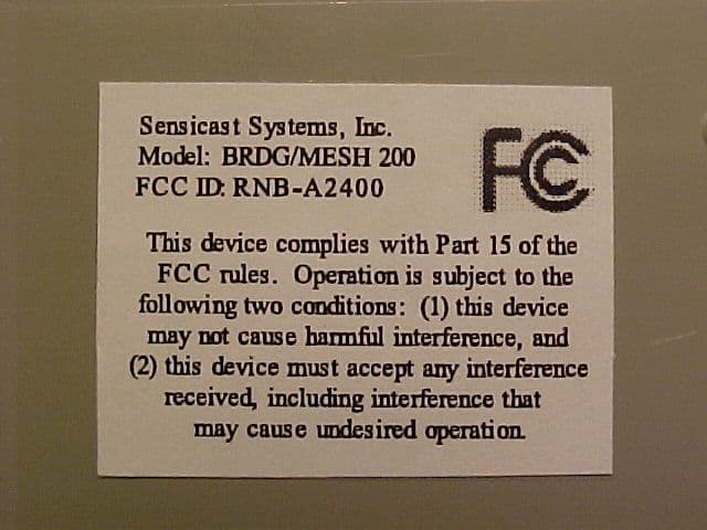
RNB-A2400
Jan 03, 2006Networking Device
Equipment Class
DTS - Digital Transmission System
RNB-OEM100
Dec 19, 2004Networking Transceiver Module
Equipment Class
DSS - Part 15 Spread Spectrum Transmitter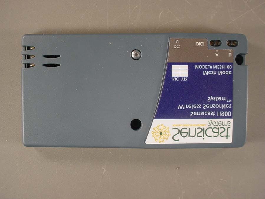
RNBF19D8MN9LQ2WFA
Dec 08, 2003Spread Spectrum Transmitter
Equipment Class
DSS - Part 15 Spread Spectrum Transmitter