RNE00594RTemperature, Humidity and RCC Transmitter
Chaney Instrument Co.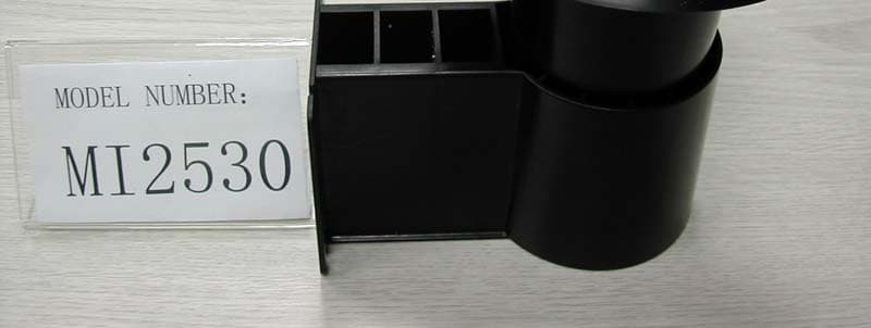
Click to zoom
Application Details
- Equipment Class
- DSC - Part 15 Security/Remote Control Transmitter
- Date of Grant
- Oct 05, 2005
- Application Purpose
- Original Equipment
- Date of Application
- Oct 05, 2005
- Equipment Note
- Temperature, Humidity and RCC Transmitter
- Frequency Range
- 433.92000000 - 433.92000000
- Company
- Chaney Instrument Co.
- Country
- China
Documents & Files
Document Text
Text extracted from the exhibit documents filed with the FCC. Open a document above to read the original.
Users Manual
MI-2531 Indoor main unit of Full Weather Station Rev (0) Dated 16/8/05 Microtech Components Ltd. Room 21, 10/Fl., Leader Industrial Building, 57-79 Au Pui Wan St., Fatan, Hong Kong Tel : (852) 23641713 Fax : (852) 23641862 Email : [email protected] 1/5 1. INTRODUCTION Remote Full weather station is composed of MI2527, MI2528, MI2529, MI2530 and MI2531. -MI2527 is outdoor temperature and humidity remote transmitter. -MI2528 is outdoor rain gauge remote transmitter. -MI2529 is outdoor wind speed and wind direction remote transmitter. -MI2530 is outdoor temperature, humidity and RCC(radio control clock) remote transmitter. -MI2531 is indoor main unit. Caution: The user is cautioned that changes and modifications made to the equipment without the approval of manufacturer could void the user's authority to operate this equipment. Notes: This equipment has been tested and found to comply with the limits for a Class B digital device, pursuant to part 15 of the FCC Rules. These limits are designed to provide reasonable protection against harmful interference in a residential installation. This equipment generates, uses and can radiate radio frequency energy and, if not installed and used in accordance with the instructions, may cause harmful interference to radio communications. However, there is no guarantee that interference will not occur in a particular installation. If this equipment does cause harmful interference to radio or television reception, which can be determined by turning the equipment off and on, the user is encouraged to try to correct the interference by one or more of the following measures: —Reorient or relocate the receiving antenna. —Increase the separation between the equipment and receiver. —Connect the equipment into an outlet on a circuit different from that to which the receiver is connected. —Consult the dealer or an experienced radio/TV technician for help. FCC Warning: This device complies with part 15 of the FCC Rules. Operation is subject to the following two conditions: (1) This device may not cause harmful interference, and (2) this device must accept any interference received, including interference that may cause undesired operation. 2. FEATURES 1) Remote receiver 2) Indoor temperature 3) Indoor humidity 4) Air pressure 5) Weather forecast 6) Radio control clock with calendar and moon face 7) Wind chill calculate 8) Heat index calculate 9) Dew point calculate 10) Time alarm, temperature alarm (outdoor & indoor), humidity alarm (outdoor & indoor), wind speed alarm, storm alarm, Rain fall alarm, wind chill alarm, heat index alarm, dew point alarm. MI-2531 Indoor main unit of Full Weather Station Rev (0) Dated 16/8/05 Microtech Components Ltd. Room 21, 10/Fl., Leader Industrial Building, 57-79 Au Pui Wan St., Fatan, Hong Kong Tel : (852) 23641713 Fax : (852) 23641862 Email : [email protected] 2/5 11) Total 8 key : MAX(+), MIN(-), DISPLAY(RECORD), CLEAR(EXIT), SETUP(ON/OFF/PRESSURE) ALARM, CHANNEL(WAVE), SNOOZE 3. FUNCTION DESCRIPTION 3-1. POWER ON or RESET When Power on or reset the LCD will full display for 5 seconds, the main unit will measure indoor temperature, indoor humidity and air pressure during this 5 seconds, then it will show the temperature, humidity value and time (default is 01/01-2005,12:00AM at EST time zone) on LCD, all of the outdoor value will be shown ---, forecast area will show cloud with blinking, pressure bar area will be clear, pressure area will show “0 METER” with METER icon blinking, it ask user to input the altitude of the station, you can press (+) or (-) key to select METER or FEET unit, then press SETUP key to set the altitude (the METER or FEET icon will become static and the “0” digit will blink), press (+) or (-) to increase or decrease the altitude with 10meter(or feet) per step, the range is from -100 to 2500 meter (or from -330 to 8250 feet). After setting the altitude, press SETUP key to confirm and go into weather setting(or press CLEAR to quit the initial setting with the cloudy weather), press (+) or (-) to set the current weather, then press CLEAR to quit the initial setting. If no key was pressed for 30 seconds, it will quit initial setting automatically with the status shown on the LCD. When completed the initial setting, it will begin to search the RF433 signal from outdoor transmitter. When turn on the rf433 module, the antenna icon will be waving to indicate signal is being picked up. When a certain signal is picked up and decoded successfully, it will be shown on LCD, and the main unit will turn off the rf433 module for 3 seconds, then to pick up next signal, the search time is maximum 6 minutes. When maximum 5 different signal is searched, it will quit search mode and go into normal mode. If the RCC signal had been received and decoded successfully, the antenna icon will be full display and the OK and WAVE icon will be light up. If no RCC signal is detected, the antenna icon will be blinking, WAVE and OK icon is disappeared. If any RCC signal had been detected (but no all), the antenna icon will be blinking, the WAVE icon is light up but the OK icon is disappeared. During the signal picked up period, the antenna icon will change to waving form. The HEAT INDEX will be calculated from the temperature and humidity value in MI2530. The WIND CHILL will be calculated from the temperature value in MI2530 and the wind speed value in MI2529. The DEW POINT will be calculated from the temperature value in MI2530. 3-2. REVIEW THE MESSAGE 3-2-1 In normal mode, press DISPLAY to view and toggle the display in cycle: WIND CHILL Æ HEAT INDEX Æ DEW POINT Æ(if rain gauge is added) Rain in last hour Total rain since last “clear” Rain in user defined days Å Rain in last 24 hours - At the total rain status, press & hold the CLEAR key for 3 seconds can clear the total rain record. MI-2531 Indoor main unit of Full Weather Station Rev (0) Dated 16/8/05 Microtech Components Ltd. Room 21, 10/Fl., Leader Industrial Building…
Text truncated - open the document above for the full version.
Cover Letter(s)
1) The Block diagram should be updated to show the oscillators for the TX module portion of the device as specified by 2.1033(b)(5) of the rules. Please update the block diagram to show the crystal oscillator to the Transmitter module and be sure to show its frequency. Wallace Reply>>>>>Please refer revised Block diagram 2) The device label appears to still need some work. Each product must have both the FCC ID and the two-part warnings of 15.19(a)(3) on the device. It appears the 2 part statement is not on this device but is only on the RX portion of the system. Please correct the device labeling to include this: This device complies with part 15 of the FCC Rules. Operation is subject to the following two conditions: (1) This device may not cause harmful interference, and (2) this device must accept any interference received, including interference that may cause undesired operation. Wallace Reply>>>>>Please refer revised label file location that we suggest client. 3) Your last response mentioned providing an updated manual containing 15.21 statements. However the recent updated manual did not appear to correct this, please add the following to the users manual and provide this updated manual: The user is cautioned that changes and modifications made to the equipment without the approval of manufacturer could void the user's authority to operate this equipment. Wallace Reply>>>>>Please refer revised user manual. 4) The users manual should also contain information regarding compliance of 15.105(b). Please update the manual to include this information or similar: Note: This equipment has been tested and found to comply with the limits for a Class B digital device, pursuant to part 15 of the FCC Rules. These limits are designed to provide reasonable protection against harmful interference in a residential installation. This equipment generates, uses and can radiate radio frequency energy and, if not installed and used in accordance with the instructions, may cause harmful interference to radio communications. However, there is no guarantee that interference will not occur in a particular installation. If this equipment does cause harmful interference to radio or television reception, which can be determined by turning the equipment off and on, the user is encouraged to try to correct the interference by one or more of the following measures: —Reorient or relocate the receiving antenna. —Increase the separation between the equipment and receiver. —Connect the equipment into an outlet on a circuit different from that to which the receiver is connected. —Consult the dealer or an experienced radio/TV technician for help. Wallace Reply>>>>>Please refer revised user manual 5) Please adjust the schematics to only show the schematics for the FCC ID of the application being reviewed. It appears the schematics currently provided may be for 3 or more different devices. Wallace Reply>>>>>Please refer revised schematic. 6) Data presented in section 4.2 appear to be for a manually activated device which does not appear to be the case for this application. Please ensure proper data is in the report and correct as necessary since the device covered by this application does not appear to be manually activated or contain buttons, therefore the information in this section of the report appears to not apply. Wallace Reply>>>>> Please refer revised test report that erase mentioned section. 7) This device appears to possibly transmit using 4 different intervals according to the operational description provided. It is uncertain if the device continues to use the same interval or if the device attempts to use pseudo-random chosen interval to meet the requirements of 15.231(a)(3) requirements below: (a)(3) Periodic transmissions at regular predetermined intervals are not permitted. However, polling or supervision transmissions, including data, to determine system integrity of transmitters used in security or safety applications are allowed if the total duration of transmissions does not exceed more than two seconds per hour for each transmitter. There is no limit on the number of individual transmissions, provided the total transmission time does not exceed two seconds per hour. However, please note that whether the device uses a set interval, or pseudo random interval, interpretations from the FCC regarding this sections of the rules do not allow for periodic transmissions, even if pseudo-random intervals are used. I have provided an interpretation in an attached exhibit which shows fact. Therefore it appears there are only 2 options available: 1) The device would be required to be certified under 15.231(e) of the rules. Please note that the device nearly meets this but it currently appears the fundamental slightly exceeds the limits by 1.4 dB and 2nd harmonic exceeds the average limit. Many other similar devices have been certified under this section of the rules. 2) To meet with 15.231 (a)(3) may only be done if the transmissions only occur if a change due to an external event has occurred. The device would NOT be allowed to transmit again unless a change due to the external event has occurred. The thresholds of these changes would be required to be explained in the report (i.e., temperature transmits only when changing by 2 degrees, etc.). However the other concern with 15.231(a)(3) is that you are not really sending a control signal, but only data. For this reason, it appears that the device will only be fully compliant following 15.231(e) option given in a unless a good explanation of what control codes are sent. Wallace Reply>>>>> Please refer revised test report that the EUT follows 15.231(e) 8) The duty cycle information provided should support the 0.5 ms data bit timing interval by showing a measurement of Wallace Reply>>>>> Please refer revised test report.
Cover Letter(s)
1) A revised block diagram as referenced in your response was not received. Please provide. Wallace Reply>>>>>Please revise attached block diagram. 2) The two-part 15.19(a)(3) statement location is still not clearly denoted. Additionally the labeling exhibits states that this is a suggested text and location. Please note that these labeling requirements are not suggestions, but FCC requirements. Please provide a final label exhibit that clearly denotes location and what is on the label. Wallace Reply>>>>> I have informed client to confirm label location, hopefully they confirm it soon. 3) The revised test report did remove the manual button information that was not applicable. However there is no information in this report to show compliance to the following: 15.231(e): In addition, devices operated under the provisions of this paragraph shall be provided with a means for automatically limiting operation so that the duration of each transmission shall not be greater than one second and the silent period between transmissions shall be at least 30 times the duration of the transmission but in no case less than 10 seconds. Data needs to be taken to show that the TX duration is < 1 second. Please provide this data. The theory of operation mentions intervals that are > 30 seconds (30 * 1 = 30), so the device appears compliant to the “30 x” requirements. However the < 1 second must be shown with data. Please provide. Wallace Reply>>>>> the transmitter active internal is 1.0 second, Please see attached reports page 20, section 4.3.7 Additional Note for the RNE00594R device. It is uncertain what the RCC function actually is. Please explain as necessary to make it clear on how this signal is compliant to the timing requirement above. RCC stands for remote control clock. Its name would imply transmitting once per second. Please explain. Wallace Reply>>>>> I have informed client to explain RCC function, hopefully they reply it soon. 3) It appears the fundamental harmonic is lower than before. Please provide a reasonable explanation for the difference in test data (was the device modified, etc.)? Wallace Reply>>>>>Surely, we ask client to modify it.
Cover Letter(s)
Hi Tim, The two questions answer is YES. Thanks, Paul From: Timothy R. Johnson [mailto:[email protected]] Sent: Friday, October 07, 2005 10:56 AM To: PAUL WU; 'adtsh' Cc: 'é™Â³Ã©Â ́Ȏʠ[major]' > Subject: RE: à ̈½‰Ã¥Â ̄„: : Uegent: Please describe RCC function Wallace/Paul, 1) So to confirm my understanding, it appears that you are saying that the software stops transmitting temperature/humidity data packets during the time it starts transmitting RCC packets. Then after RCC is finished, it will return to temperature/humidity packets. Yes 2) The software ensures that the * 30 silent period (30 seconds or greater for this device) will always be maintained before/after the RCC packets. Yes Thanks, Tim At 10:45 AM 10/7/2005 +0800, PAUL WU wrote: à ̄»¿ Hi Tim / Wallace, Please see below for my reply. I hop it is helpful. Thanks, Paul Page 1 of 4PAUL WU, 11:00 AM 10/7/2005 +0800, RE: à ̈½‰Ã¥Â ̄„: Uegent: Please 10/6/2005Printed for "Timothy R. Johnson" <[email protected]> From: adtsh [ mailto:[email protected]] Sent: Friday, October 07, 2005 10:24 AM To: 'Timothy R. Johnson'; Paul Wu Cc: ' é™Â³Ã©Â ́ȎÂâ € [major]' Subject: å⠀ºžÃ ̈¦† : à ̈½‰Ã¥Â ̄„ > : Uegent: Please describe RCC function Dear Tim: Thank you for your quickly reponse, I also copy your mail to client Mr. Paul Wu, He would be reply your question. Dear Paul: Could you reply Tim's question soon mentioned in mail ? Thank you. Regards! ************************************ Wallace Pan Manager ADT (Shanghai) Corporation 2F, Building C, No.1618, Yishan rd., 201103, Shanghai, China TEL : +86-21-6465-9091 ext 201 Fax : +86- 21-6465-9092 Mobile: +86-1381-782-5365 E-mail: [email protected] MSN à ̄¼š [email protected] SKYPE: wallace_pan ************************************* å ̄ä»Â¶à ̈€...: Timothy R. Johnson [ mailto:[email protected]] å ̄件æâ—¥æ: 2005å¹ ́10æ7æ—Â¥ Â¥ 10:15 憶件à ̈â¬...: adtsh å ̄æ¬: 'é³é ́Ȏʠ[major]' > ä ̧Ⱦ— ̈: Re: à ̈½å ̄: Uegent: Please describe RCC CC function Wallace, OK....I think I understand and we therefore need a little more information. To recap my understanding, the RCC signal is received from an external source to the system. It is received by the Temp/Humidity/RCC device and rebroadcast back to the system receiver only once or twice per day. Yes. It is correct. The RCC signal appears to be a separate transmission from what was stated below. However, if the device wants to transmit a Temp/Humidity packet (that is retransmitted every 41, 47, 51, or 53 seconds), and also rebroadcast the RCC signal, what insures that the 30 * silent period is maintained both before and after the RCC signal is rebroadcast. The transmitter will send out the time packets by few times with 41, 47, 51 or 53 seconds. After completed the RCC signal transmission, it will start to send out the temp/humidity data with 41, 47, 51, and 53 seconds. The software would have to be designed to ensure that both an RCC rebroadcast and also temp/humidity packet don't occur within the same 41/47/51/53 second cycle. Yes, they are not in the same packet. Thanks, Page 2 of 4PAUL WU, 11:00 AM 10/7/2005 +0800, RE: à ̈½‰Ã¥Â ̄„: Uegent: Please 10/6/2005Printed for "Timothy R. Johnson" <[email protected]> Tim At 09:50 AM 10/7/2005 +0800, adtsh wrote: Dear Tim: The following mail is RCC explaination from client, please review it. TKS! ************************************ Wallace Pan Manager ADT (Shanghai) Corporation 2F, Building C, No.1618, Yishan rd., 201103, Shanghai, China TEL : +86-21-6465-9091 ext 201 Fax : +86-21-6465-9092 Mobile: +86-1381-782-5365 E-mail: [email protected] MSNáG [email protected] SKYPE: wallace_pan ************************************* ±H¥óªÃŒ: PAUL WU [ mailto:[email protected] ] ñHÃ¥óäéà́à: 2005æ~10äë7äé 9:09 æìÃ¥óêÃ: 'adtsh'; 'kelvin' ÃÂ¥Dæî: RE: Uegent: Please describe RCC function Hi Wallace, Regarding the RCC function, we implemented a RCC receiver WWVB (60KHz) receiver in the outdoor transmitter (thermo). The RCC receiver will start to receive the RCC single when first power on and 2:00am everyday. It will keep tune on the RCC receiver for 10 min in each time in order to receive the completer RCC single. After well received the RCC single, the transmitter will transmit the time single to the base (indoor receiver). The transmitter will break down the time single to few packages and transmit to the receiver. In each time transmission is less than 1s and the time interval is more than 30s (same data format with 594R). Thanks, Paul From: adtsh [ mailto:[email protected] ] Sent: Friday, October 07, 2005 5:37 AM To: 'PAUL WU'; 'kelvin' Subject: Uegent: Please describe RCC function Dear Paul and Kevin: Sorry for our delay your project RNE00594W and RNE00594R. Attached please find grant of RNE00594W. However, for RNE00594R, we still lack for RCC function ab below: According to TCN opinion: Additional Note for the RNE00594R device. It is uncertain what the RCC function actually is. Please explain as necessary to make it clear on how this signal is compliant to the timing requirement above. RCC stands for remote control clock. Its name would imply transmitting once per second. Please explain. Page 3 of 4PAUL WU, 11:00 AM 10/7/2005 +0800, RE: à ̈½‰Ã¥Â ̄„: Uegent: Please 10/6/2005Printed for "Timothy R. Johnson" <[email protected]> Please provide it mention above ASAP. Regards! ************************************ Wallace Pan Page 4 of 4PAUL WU, 11:00 AM 10/7/2005 +0800, RE: à ̈½‰Ã¥Â ̄„: Uegent: Please 10/6/2005Printed for "Timothy R. Johnson" <[email protected]>
Operational Description
Hong Kong Primex Asia Limited Design Information of Full Weather Station 1. SPEC 2. SOFTWARE INFORMATION 3. BOM 4. FCC LABEL 5. RF TX SCH 6. RF RX SCH 7. Outdoor, wind speed and wind direction remote transmitter SCH. 8. Outdoor, temperature, humidity and RCC(radio control clock) remote transmitter SCH. 9. RF TX layout 10. RF RX layout 11.Outdoor, wind speed and wind direction remote transmitter layout. 12.Outdoor,temperature, humidity and RCC(radio control clock) remote transmitter layout. SOFTWARE INFORMATION Chapter 1: Function Summarize The software is designed for the project “Full Weather Station”, it include a. Wireless transmission of the temperature humidity RCC wind speed, wind direction and pressure of the outdoor and indoor; b. Sensor send the information to a wireless receiver inside the home; c. Transmission range up to 100ft. in open area; d. The system must work normally more than 12 months; e. When running at room temperature, the error is no more than +/-1°C or+/-3°F. f. When running at room pressure, the error is no more than +/-2mpha. g. When running at open area wind speed, the error is no more than 0.3ft. h, When running at room humidity , the error is no more than 5%. Chapter 2: Operating Condition 2.1 Operating Temperature Sender -30 to 70°C (-22 to 158 °F) Receiver 0 to 70 °C (32 to 158 °F) 2.2 Operating Voltage Sender 2.4 to 3.6 V Receiver 4.0 to 4.6 V 2.3 Storage Temperature -40 to 75 °C (-40 to 167 °F) Chapter 3: MCU information Remote Full weather station is composed of MI2529, MI2530 and MI2531. -MI2529(HT48R10) is outdoor wind speed and wind direction remote transmitter. -MI2530(HT48R30) is outdoor temperature, humidity and RCC(radio control clock) remote transmitter. -MI2531(HT46R24) is indoor main unit. HARDWARE INFORMATION Hong Kong Primex Asia Limited Full Weather Station is Three product that is designed to show the indoor and outdoor temperature , humidity , RCC(radio control clock) , pressure ,wind speed and wind direction ...,wireless (within 60 feet). It base as fellows: Outdoor Unit Using MCU to test the resistor of NTC temperature sensor, and count current temperature, Test the resistor of humidity sensor, and count current humidity. Receiver UE6010 RCC, Then transmitting the encoded data package through the outdoor helix antenna by ASK modulated with 433.92MHz frequency. Indoor Unit Receiving the RF signal by PCB antenna, passing LNA, Super-regeneration Amplifier, Demodulator, operating Amplifier, LPF , then decoding the outdoor temperature, RCC humidity, wind speed and wind direction in data package; Otherwise, MCU still test indoor NTC temperature sensor, humidity pressure and calculate the current indoor temperature, humidity, pressure, wind speed, wind direction and display the two temperature value ...in LCD at the same. The transmitting distance: 60 feet ( Open area) Battery: MI2529 /MI2530 two AA battery MI2531 three AA battery The battery life: not less one year. Transmitting times: MI2529 Transmit times interval: 31,37,39 ,41.SEC MI2530 Transmit times interval: 43,47,51 ,53.SEC Products standard FCC PART15-22 SECTION19.231 Tx Electrical Characteristics Vcc Operating supply voltage: 2.4~ 3 3.6 V Icc Peak Current Connect Tx :6.5 ~9.5 mA Icc Standby Current No Tx: 0.02 ~0.04 mA F0 Absolute Frequency :433.72 ~ 434.12 MHz Po RF Output Power Vcc = +3V D=3m @-25~-20 dBm Tc Operating: -30 ~ 70 °C Notes: Case temperature = 25°C±2°C Rx Electrical Characteristics Vcc Operating supply voltage: 3.5 ~ 4.6 V Sensitivity=-102dBm Icc Operating Current In Rx: 2 ~ 4 mA Icc Standby Current No Rx :0.02 ~0.04 mA FC :Operation Radio Frequency Sensitivity=-102dBm @432.92 ~434.92 MHz Hong Kong Primex Asia Limited Pref @ Sensitivity 3% Mistake For Code -98 ~-103 dBm Receiver Turn On Time :400 ms Notes: Case temperature = 25°C±2°C,Test Load Impedance=50ohm Hong Kong Primex Asia Limited Hong Kong Primex Asia Limited Hong Kong Primex Asia Limited
Test Report
Report No.: 050912FIA02 1 Report Format Version 1.0.1 FCC TEST REPORT REPORT NO.: 050912FIA02 MODEL NO.: MI2530 RECEIVED: Sept 19, 2005 TESTED: Sept 19 ~ Sept 30, 2005 ISSUED: Sept 30, 2005 APPLICANT: Chaney Instrument Co. ADDRESS: AB 29/F HaiYing Building South Caitian Road Futian District Shenzhen China ISSUED BY: ADT (Shanghai) Corporation ADDRESS: 2F, Building C, No.1618, Yishan rd., 201103, Shanghai, China This test report consists of 22 pages in total. It may be duplicated completely for legal use with the approval of the applicant. It should not be reproduced except in full, without the written approval of our laboratory. The client should not use it to claim product endorsement by A2LA, NVLAP or any government agencies. The test results in the report only apply to the tested sample. ADT (Shanghai) Corporation. Report No.: 050912FIA02 2 Report Format Version 1.0.1 Table of Contents 1 CERTIFICATION ............................................................................................. 3 2 SUMMARY OF TEST RESULTS ..................................................................... 4 2.1 MEASUREMENT UNCERTAINTY............................................................... 4 3 GENERAL INFORMATION.............................................................................. 5 3.1 GENERAL DESCRIPTION OF EUT ............................................................ 5 3.2 DESCRIPTION OF TEST MODES .............................................................. 5 3.3 DESCRIPTION OF SUPPORT UNITS ........................................................ 7 3.4 DESCRIPTION OF SUPPORT UNITS ........................................................ 7 4 EMISSION TEST ............................................................................................. 8 4.1 CONDUCTED EMISSION MEASUREMENT............................................... 8 4.1.1 LIMITS OF CONDUCTED EMISSION MEASUREMENT ............................ 8 4.1.2 TEST RESULT............................................................................................. 8 4.2 20DB OCCUPIED BANDWIDTH MEASUREMENT .................................... 9 4.2.1 LIMITS OF BAND EDGES MEASUREMENT .............................................. 9 4.2.2 TEST INSTRUMENTS................................................................................. 9 4.2.3 TEST PROCEDURES ................................................................................. 9 4.2.4 DEVIATION FROM TEST STANDARD........................................................ 9 4.2.5 TEST SETUP............................................................................................. 10 4.2.6 TEST RESULTS ........................................................................................ 10 4.3 RADIATED EMISSION MEASUREMENT.................................................. 11 4.3.1 LIMITS OF RADIATED EMISSION MEASUREMENT ............................... 11 4.3.2 TEST INSTRUMENTS............................................................................... 13 4.3.3 TEST PROCEDURE.................................................................................. 14 4.3.4 DEVIATION FROM TEST STANDARD...................................................... 14 4.3.5 TEST SETUP............................................................................................. 15 4.3.6 EUT OPERATING CONDITIONS .............................................................. 15 4.3.7 TEST RESULTS ........................................................................................ 16 5 PHOTOGRAPHS OF THE TEST CONFIGURATION .................................... 21 6 PHOTOGRAPHS OF THE EUT .................................................................... 22 7 APPENDIX - INFORMATION ON THE TESTING LABORATORIES ............. 24 Report No.: 050912FIA02 3 Report Format Version 1.0.1 1 CERTIFICATION PRODUCT: Full weather station MODEL NO.: MI2530 APPLICANT: Chaney Instrument Co. TESTED: Sept 19 ~ Sept 30, 2005 TEST ITEM: Engineering Sample STANDARDS: FCC Part 15:2005, Subpart A (Section 15.35), Subpart C (Section 15.207,15.209 and 15.231) ANSI C63.4-2003 The above equipment has been tested by ADT (Shanghai) Corporation, and found compliance with the requirement of the above standards. The test record, data evaluation & Equipment Under Test (EUT) configurations represented herein are true and accurate accounts of the measurements of the sample’s EMC characteristics under the conditions specified in this report. TECHNICAL ACCEPTANCE : , DATE:SPET 30, 2005 Responsible for EMI (Wailand Zhang) APPROVED BY : , DATE:SPET 30, 2005 (Wallace Pan, Manager ) Report No.: 050912FIA02 4 Report Format Version 1.0.1 2 SUMMARY OF TEST RESULTS The EUT has been tested according to the following specifications: APPLIED STANDARD: FCC Part 15, Subpart C Standard Paragraph Test Type ResultRemarks 15.207 Conducted Emission Test N/A 15.231(c) 20dB Occupied Bandwidth Measurement PASS Meet the requirement of limit 15.209 15.231(e) Radiated Emission Test PASS Minimum passing margin is –1.03dB at 3037.440MHz Note: This report contains data that were produced under subcontract by Laboratory ADT (Shanghai) Corporation. 2.1 MEASUREMENT UNCERTAINTY Where relevant, the following measurement uncertainty levels have been estimated for tests performed on the EUT as specified in CISPR 16-4: Measurement Value Conducted emissions 1.8dB Radiated emissions 3.5dB Report No.: 050912FIA02 5 Report Format Version 1.0.1 3 GENERAL INFORMATION 3.1 GENERAL DESCRIPTION OF EUT PRODUCT Full weather station MODEL NO. MI2530 POWER SUPPLY 3 Vdc from battery MODULATION TYPE ASK CARRIER FREQUENCY OF EACH CHANNEL 433.92MHz NUMBER OF CHANNEL 1 ANTENNA TYPE Soldered on PCB DATA CABLE SUPPLIED N/A I/O PORTS N/A NOTE: The above EUT information was declared by manufacturer and for more detailed features description, please refer to the manufacturer's specifications or User's Manual. 3.2 DESCRIPTION OF TEST MODES One channel is provided to this EUT: C…
Text truncated - open the document above for the full version.
Contact Information
Applicant
Victor Mak(Project Manager - Digital Products)
Technical Contact
ADT (Shanghai) CorporationWallace Pan
[email protected]+86-21-6465-9091
2F, Building C, No. 1618, Yishan rd. · Shanghai · China
Test Firm
BUREAU VERITAS ADT (Shanghai) CorporationZhaoqian YU
Technical Specifications
| # | Rule Parts | Frequency Range | Power Output |
|---|---|---|---|
| 1 | 15.231(e) | 433.92 MHz - 433.92 MHz | - |
Other Applications from Chaney Instrument Co.

RNEVN1TXCA5
Mar 27, 2026AcuRite IrisTM (5-in-1) Weather Sensor(Single Solar Panel), AcuRite IrisTM(5-in-1) Weather Sensor(Dual Solar Panel)
Equipment Class
DSC - Part 15 Security/Remote Control Transmitter
RNEVN1TXCA4
Dec 12, 2025AcuRite Iri TM (5-in-1) Weather Sensor(Single Solar Panel), AcuRite Iri TM (5-in-1) Weather Sensor(Dual Solar Panel)
Equipment Class
DSC - Part 15 Security/Remote Control Transmitter
RNE01194TX
Nov 04, 2020Wireless Charging Forecaster
Equipment Class
DCD - Part 15 Low Power Transmitter Below 1705 kHz
RNE00515TX
Jan 19, 2020Digital Freezer /Refrigerator Thermometer
Equipment Class
DSC - Part 15 Security/Remote Control Transmitter
RNEVN1TXCA2
Aug 09, 2015Professional Weather Center
Equipment Class
DSC - Part 15 Security/Remote Control Transmitter