RNW-AQL-RF-PS-XXWireless Remote Display
Hayward Industries, Inc.Application Details
- Equipment Class
- DXX - Part 15 Low Power Communication Device Transmitter
- Date of Grant
- Oct 05, 2004
- Application Purpose
- Original Equipment
- Date of Application
- Oct 05, 2004
- Equipment Note
- Wireless Remote Display
- Frequency Range
- 902.00000000 - 928.00000000
- Company
- Hayward Industries, Inc.
- Country
- United States
Documents & Files
Document Text
Text extracted from the exhibit documents filed with the FCC. Open a document above to read the original.
Users Manual
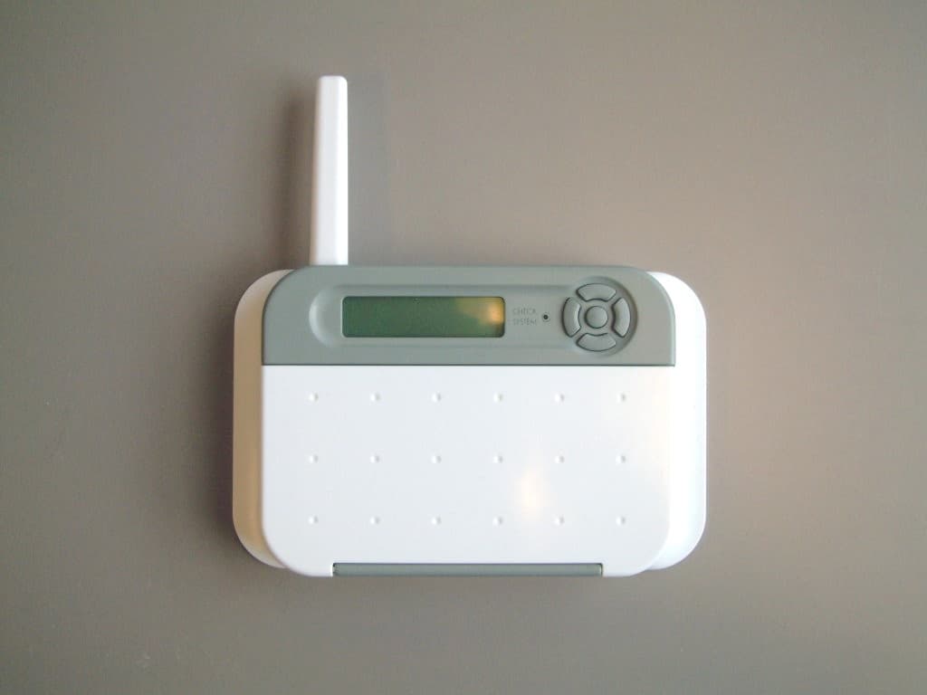
Wireless Remote Display for Aqua LogicAqua Logic Aqua LogicAqua Logic Aqua Logic Automation and Chlorination (model AQL-REMOTE-RF-PS-8 shown above) Installation/Operation Manual for model AQL-REMOTE-RF-PS-4 AQL-REMOTE-RF-PS-8 AQL-REMOTE-RF-PS-16 LDLINE CONTROLS INC. G www.goldlinecontrols.com Compatibility This product is compatible with all Aqua Logic controls operating with software revision r2.00 or higher and Base Receivers with software revision r1.20 or higher. To verify the software level of your Aqua Logic control, press the Menu button (possi- bly multiple times) until “Diagnostic Menu” is displayed. Press the “>” or “<“ keys (possibly multiple times) until the main software revision level is displayed (the revi- sion should be 2.00 or higher). Next, press the ">" key (possibly multiple times) until the "RF Base" revision level is shown (the revision should be 1.20 or higher). If the software revision level is less than those specified above, contact the Goldline Technical Service Dept. from Monday through Friday, 8AM to 8PM Eastern at 888- 921-7665 for information on upgrades. Installation 1.Base Receiver required: For operation of the wireless remote display/keypad, the Aqua Logic control unit must have a base receiver (AQL-BASE-RF) in- stalled. The receiver allows the Aqua Logic control until to communicate with the spa-side remote. 2.Select Location: There are several considerations in choosing the location for the wireless remote display/keypad: Protected from the weather: The wireless remote display/keypad must be mounted indoors or in a weather protected area (rain should never hit the wireless remote display/keypad). The wireless remote display/keypad is designed to mount onto a standard electrical utility box (same size as used for a triple light switch) or can be mounted directly onto any wall surface. Within range of Base Receiver: The wireless remote display/keypad must be installed within 200 ft. (assuming the signal will have to travel through walls) or 400 ft. (line of sight) from the Base Receiver which is typically mounted on the Aqua Logic main control unit at the pool equipment pad. The Base Receiver can also be mounted up to 500 ft. away from the main control unit to shorten the distance between it and any wireless remote. See the "Remote Mounting of the Base Receiver" section of the Base Receiver manual for more details. Near 120V wall outlet: The wireless remote display/keypad uses a plug-in power supply with a 6 ft. cable. 3.Mount on wall: The wireless remote display/keypad must be mounted indoors or in a weather protected area (rain should never hit the display/keypad). Refer to the diagram on the following page. a.Remove the wireless remote display/keypad baseplate from the cover by lifting up on the cover at the lower end of the keypad. b.Thread the wall mount power supply’s output connector from behind and through the opening in the left side of the baseplate. c.Screw the baseplate in the desired position (screws supplied by installer). d.Plug the power supply’s output connector into the mating connector on the back of the wireless remote display/keypad. 1 e.Reattach the wireless remote display/keypad to the baseplate. f.Plug the power supply into a 120VAC outlet. 4.Teach the unique Aqua Logic ID code: The base receiver attached to the Aqua Logic control unit has a unique ID code that ensures that your unit will not affect other systems in the neighborhood, and likewise, their remote will not affect your system. To teach the ID code to the wireless remote unit: a.On any other Aqua Logic display/keypad unit, press the “Menu” button (possibly multiple times) until “Settings Menu” is displayed. b.Press “<“ or “>” (again, possibly multiple times) until “Teach Wireless” is displayed. c.Press the “+” button to start the teaching pro- cess. d.Press and hold any button on the wireless re- mote display/keypad for 4 seconds. At this point the LCD on the wireless remote display/ keypad will indicate "Teach Wireless Success- ful" and the local display/keypad on the Aqua Logic control unit will also confirm “Teach Wireless Successful”. If this process is not successful, then refer to the Troubleshooting section of this manual for additional informa- tion. 5.Apply labels: The Aqua Logic PS series of controls allow each output (e.g. AUX1) to be renamed to what is actually being controlled. The wireless remote display/keypad comes with a sheet of name labels—simply peel the appropriate label off the sheet and apply to the appropriate set of buttons on the wireless remote display/keypad. 6.Installation is complete: You can now use the wireless remote display/keypad. 2 Settings Menu Teach Wireless: + to start Teach Wireless: Successful Press and hold wireless button Pull up on bottom edge to remove cover Wireless Remote Display unit OPERATION The wireless remote display/keypad communicates with the base receiver on the Aqua Logic control unit using RF (radio frequency) technology. All of the display information is transmitted from the Aqua Logic control unit to the wireless remote display/keypad and all the button press information is transmitted by the Remote RF unit back to the Aqua Logic control unit. If the display information is not being updated on a regular basis or if the Aqua Logic is not responding to buttons being pressed, then refer to the Troubleshooting sec- tion for assistance in resolving these problems. When power is turned on, all the LED indicators will flash briefly, the display back- light will illuminate, and the following display will appear for a short period of time: The "r1.00" is the software revision level. The actual revision level for your wireless remote display/keypad may be different. Refer to the Aqua Logic Operation Manual for complete operating instructions. TROUBLESHOOTING 1.Can’t find the “Teach Wireless” display: Press the “menu” button (possibly more than once) until “Settings Menu” is displayed. Next, press the “<“ or “>” buttons…
Text truncated - open the document above for the full version.
Cover Letter(s)
61 Whitecap Dr., North Kingstown, RI 02852 Tel: 800-343-0826 / 401-583-1100 Fax: 401-583-1200 www.goldlinecontrols.com F C C CONFIDENTIALITY Date: 05/24/04 To: FEDERAL COMMUNICATIONS COMMISSION 7435 Oakland Mills Road Columbia, MD 21046 Subject: Request for Non disclosure for FCC ID: RNW–AQL-RF-PS-XX . To Whom It May Concern: Pursuant to 47 CFR Section 0.459, _Goldline Controls, Inc. hereby requests non disclosure and confidential treatment of the following materials submitted in support of FCC certification application for FCC ID # ( RNW-AQL-RF-PS-XX ) a. Schematic Diagrams b. Operational Description c. Block Diagram Above materials contain trade secrets, proprietary and technical information which would customarily be guarded from competitors under 47 CFR section 0.457(d)(2). Disclosure or publication of any portion of this company confidential material to other parties could cause substantial competitive harm and provide unjustified benefits for competitors. Goldline Controls, Inc. understands that pursuant to 47 CFR section 0.457(d)(1)(ii) disclosure of the applicant and all accompanying documentation will not be made before the date of the grant. Dated this ___24 th _day of __May__, 2004 Signed: By: Charles Savoie Title: Engineering Manager / Goldline Controls, Inc. Phone: 401-583-1103
Cover Letter(s)
Response to TCB Findings 1. The FCC ID and the compliance statement (15.19(a)(3)) can not be on separate labels as required by 2.925(a)(2). Corrected label sample to include both in a single label and placement photo of it will be needed. Corrected label and placement photo supplied.
External Photos
Goldline Controls Incorporated AquaLogic Remote Transceiver 902 – 926 MHz Radio FCC ID#: RNW-AQL-RF-PS-XX Photo One – External Base Unit with Control Cover Closed Goldline Controls Incorporated AquaLogic Remote Transceiver 902 – 926 MHz Radio FCC ID#: RNW-AQL-RF-PS-XX Photo Two – External Base Unit with Control Cover Open Goldline Controls Incorporated AquaLogic Remote Transceiver 902 – 926 MHz Radio FCC ID#: RNW-AQL-RF-PS-XX Photo Three – External Base Unit – Back Side with FCC Labels Goldline Controls Incorporated AquaLogic Remote Transceiver 902 – 926 MHz Radio FCC ID#: RNW-AQL-RF-PS-XX Photo Four – External Base Unit – Back Side with FCC Part 15 Statement Goldline Controls Incorporated AquaLogic Remote Transceiver 902 – 926 MHz Radio FCC ID#: RNW-AQL-RF-PS-XX Photo Five – External Base Unit – Back Side with FCC ID Label
ID Label/Location Info
4.000 3.000 4xR0.063 Notes: 1. Labelstock: 2.0 mil Glossy White Polyester 2. Advesive: 1.9-2.1a mil Permanent Acrylic 3. Liner: 3.1 mil 50# paper 4. Ink Material: Resin, RB-8040 A Released 11/22/03 1.400 .970 3xR0.60 B 1.7500.375 4xR0.063 1.250 4xR0.063 .375 .060 .060 DETAIL B SCALE 3 : 1 REVISIONS DESCRIPTION REV. DATE APPROVED ZONE Goldline Controls, inc. Goldline Controls, inc.Goldline Controls, inc. Goldline Controls, inc. DESIGN CONTROL GOLDLINE MFG'SXX UL CONTROL XX NONE OTHER CONTROLS MANUFACTURER / VENDOR ANY XX SPECIFIC Label Kit, 4" x 4" 955000A DESCRIPTIONVARIATION DO NOT SCALE DRAWING 61 Whitecap Drive North Kinstown, RI 02852 UNLESS OTHERWISE SPECIFIED: DIMENSIONS ARE IN INCHES TOLERANCES: FRACTIONAL 1/10 ANGULAR: MACH 1 BEND 1 TWO PLACE DECIMAL 0.01 THREE PLACE DECIMAL 0.005 PROPRIETARY AND CONFIDENTIAL THE INFORMATION CONTAINED IN THIS DRAWING IS THE SOLE PROPERTY OF GOLDLINE CONTROLS INC. ANY REPRODUCTION IN PART OR AS A WHOLE WITHOUT THE WRITTEN PERMISSION OF GOLDLINE CONTROLS INC. IS PROHIBITED. DRAWING SCALE: 1:1 S.Kempski 6/23/2004 A Label Kit, 4" x 4" APPROVED BY: DATE: DRAWN BY: 955000 SHEET 1 OF 1 REV PART NUMBER: A SIZE DRAWING TITLE:
Internal Photos
Goldline Controls Incorporated AquaLogic Remote Transceiver 902 – 926 MHz Radio FCC ID#: RNW-AQL-RF-PS-XX Photo One – Internal Open for Inspection Goldline Controls Incorporated AquaLogic Remote Transceiver 902 – 926 MHz Radio FCC ID#: RNW-AQL-RF-PS-XX Photo Two – Internal PCB inside the Case with Power Cord and Antenna Goldline Controls Incorporated AquaLogic Remote Transceiver 902 – 926 MHz Radio FCC ID#: RNW-AQL-RF-PS-XX Photo Three – Internal PCB Close-up of RF Section Goldline Controls Incorporated AquaLogic Remote Transceiver 902 – 926 MHz Radio FCC ID#: RNW-AQL-RF-PS-XX Photo Four – Internal PCB Antenna Connection Goldline Controls Incorporated AquaLogic Remote Transceiver 902 – 926 MHz Radio FCC ID#: RNW-AQL-RF-PS-XX Photo Five – Internal PCB Flip Side Goldline Controls Incorporated AquaLogic Remote Transceiver 902 – 926 MHz Radio FCC ID#: RNW-AQL-RF-PS-XX Photo Six – Internal PCB Flip Side RF Section
Test Report
L.S. Compliance, Inc. W66 N220 Commerce Court Cedarburg, WI 53012 262-375-4400 Fax: 262-375-4248 COMPLIANCE TESTING OF: PS RF-Remote PREPARED FOR: Goldline Controls, Incorporated Attention: Mr. Charles Savoie 61 Whitecap Drive North Kingstown, RI 02852 TEST REPORT NUMBER: 304262 TX TCB Rev. 1 TEST DATE(S): May 27 th through June 1 St , 2004 All results of this report relate only to the items that were tested. This report is not to be reproduced, except in full, without written approval of L. S. Compliance, Inc. L.S. Compliance, Inc. Page 2 of 28 Test Report Number: 304262 TX TCB Rev. 1 Prepared For: Goldline Controls, Inc. Table of Contents Section Description Page Index 2 1 L. S. Compliance in Review 3 2 A2LA Certificate of Accreditation 4 3 A2LA Scope of Accreditation 5 4 Validation Letter-U.S. Competent Body for EMC Directive 89/336/EEC 6 5 Signature Page 7 6 Product and General Information 8 7 Introduction 8 8 Product Description 9 9 Test Requirements 10 10 Summary of Test Report 10 11 Radiated Emissions Test 11-19 12 Conducted Emissions Test, AC Power Line 20-24 13 Band-Edge Measurements 25-26 14 Frequency and Power Stability across input voltage 27 Appendix A Test Equipment List 28 L.S. Compliance, Inc. Page 3 of 28 Test Report Number: 304262 TX TCB Rev. 1 Prepared For: Goldline Controls, Inc. 1. L. S. Compliance In Review L.S. Compliance - Accreditations and Listing’s As an EMC Testing Laboratory, our Accreditation and Assessments are recognized through the following: A2LA – American Association for Laboratory Accreditation Accreditation based on ISO/IEC 17025 : 1999 with Electrical (EMC) Scope of Accreditation A2LA Certificate Number: 1255.01 Federal Communications Commission (FCC) – USA Listing of 3 Meter Semi-Anechoic Chamber based on Title 47 CFR – Part 2.948 FCC Registration Number: 90756 Listing of 3 and 10 meter OATS based on Title 47CFR – Part 2.948 FCC Registration Number: 90757 Industry Canada On file, 3 Meter Semi-Anechoic Chamber based on RSS-212 – Issue 1 File Number: IC 3088-A On file, 3 and 10 Meter OATS based on RSS-212 – Issue 1 File Number: IC 3088 U. S. Conformity Assessment Body (CAB) Validation Validated by the European Commission as a U. S. Competent Body operating under the U. S. /EU, Mutual Recognition Agreement (MRA) operating under the European Union Electromagnetic Compatibility –Council Directive 89/336/EEC, Article 10.2. Date of Validation: January 16, 2001 Validated by the European Commission as a U.S. Notified Body operating under the U.S./EU, Mutual Recognition Agreement (MRA) operating under the European Union Telecommunication Equipment – Council Directive 99/5/EC, Annex V. Date of Validation: November 20, 2002 Notified Body Identification Number: 1243 L.S. Compliance, Inc. Page 4 of 28 Test Report Number: 304262 TX TCB Rev. 1 Prepared For: Goldline Controls, Inc. 2. A2LA Certificate of Accreditation L.S. Compliance, Inc. Page 5 of 28 Test Report Number: 304262 TX TCB Rev. 1 Prepared For: Goldline Controls, Inc. 3. A2LA Scope of Accreditation L.S. Compliance, Inc. Page 6 of 28 Test Report Number: 304262 TX TCB Rev. 1 Prepared For: Goldline Controls, Inc. 4. Validation Letter – U.S. Competent Body for EMC Directive 89/336/EEC L.S. Compliance, Inc. Page 7 of 28 Test Report Number: 304262 TX TCB Rev. 1 Prepared For: Goldline Controls, Inc. 5. Signature Page Prepared By: September 29, 2004 Teresa A. White, Document Coordinator Date Tested By: September 29, 2004 Abtin Spantman, EMC Engineer Date Approved By: September 29, 2004 Kenneth L. Boston, EMC Lab Manager Date PE #31926 Licensed Professional Engineer Registered in the State of Wisconsin, United States L.S. Compliance, Inc. Page 8 of 28 Test Report Number: 304262 TX TCB Rev. 1 Prepared For: Goldline Controls, Inc. 6. Product and General Information Manufacturer: Goldline Controls, Inc. Date(s) of Test: May 27 th – June 1 st , 2004 Test Engineer(s): Tom Smith √ Abtin Spantman Ken Boston Model #: PS RF-Remote Serial #: Pre-production sample Voltage: 9 VDC Operation Mode: Continuous Transmit and normal mode as needed. 7. Introduction Between May 27 TH and June 1 ST , 2004, a series of Conducted and Radiated Emission tests were performed on one pre-production sample of the Goldline Controls’ PS RF- Remote, here forth referred to as the “Equipment Under Test” or “EUT”. These tests were performed using the procedures outlined in ANSI C63.4-2001 for intentional radiators, and in accordance with the limits set forth in FCC Part 15.249 (Industry Canada RSS-210) for a low power transmitter. These tests were performed by Abtin Spantman, EMC Engineer at L.S. Compliance, incorporated. All Radiated and Conducted Emission tests were performed upon the EUT to measure the emissions in the frequency bands described in Title 47 CFR, FCC Part 15, including 15.35, 15.209, 15.249 and Industry Canada RSS-210 to determine whether these emissions are below the limits expressed within the standards. These tests were performed in accordance with the procedures described in the American National Standard for methods of measurement of Radio-Noise Emissions from Low-Voltage Electrical and Electronic Equipment in the Range of 9 kHz to 40 GHz (ANSI C63.4- 2001). Another document used as a reference for the EMI Receiver specification was the Comite International Special Des Perturbations Radioelelectriques (CISPR) Number 16-1, 2002. L.S. Compliance, Inc. Page 9 of 28 Test Report Number: 304262 TX TCB Rev. 1 Prepared For: Goldline Controls, Inc. 8. Product Description The Goldline PS RF-Remote provides a remote wireless solution for a Spa controller system. The system is composed of a “Base Unit” containing the transceiver and control circuitry for the Spa, and a “Remote Controller Unit” containing a transceiver and keypad. The base and PS RF-Remote units comprise a remote control system that utilizes a 5 channel scanning scheme to obtain a clear channel. Base receiver will continuously scan 5 channels for a signal from the remote…
Text truncated - open the document above for the full version.
Test Setup Photos
Goldline Controls, Inc. Photos Taken During Radiated Emission Testing Setup for the Radiated Emissions Test Front View of the EUT during testing Rear View of the EUT during testing Goldline Controls, Inc. Photo(s) Taken During Conducted Emission Testing Setup for the Conducted Emissions Test
Contact Information
Applicant
John O'Hare(Senior Manager Product Compliance)
Test Firm
LS Research, LLCRyan Urness
Technical Specifications
| # | Rule Parts | Frequency Range | Power Output |
|---|---|---|---|
| 1 | 15C | 902 MHz - 928 MHz | - |
Other Applications from Hayward Industries, Inc.
RNW-MD-FH-09-01
Jan 24, 2007902-927 MHz Frequency Hopping Radio Module
Equipment Class
DSS - Part 15 Spread Spectrum Transmitter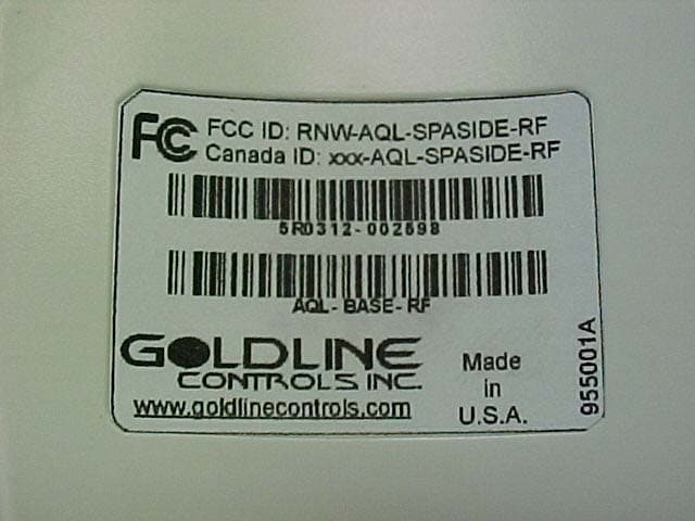
RNW-AQLSPASIDE-RF
Feb 11, 2004Remote Control
Equipment Class
DXX - Part 15 Low Power Communication Device Transmitter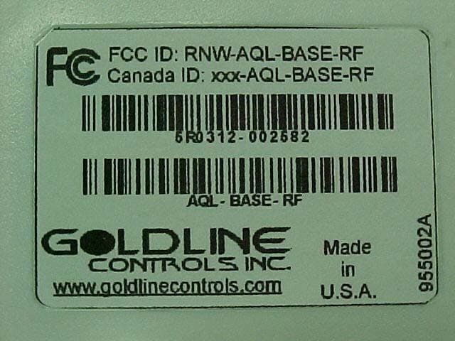
RNW-AQL-BASE-RF
Feb 11, 2004RF Base Station
Equipment Class
DXX - Part 15 Low Power Communication Device Transmitter