RNW-MD-FH-09-01902-927 MHz Frequency Hopping Radio Module
Hayward Industries, Inc.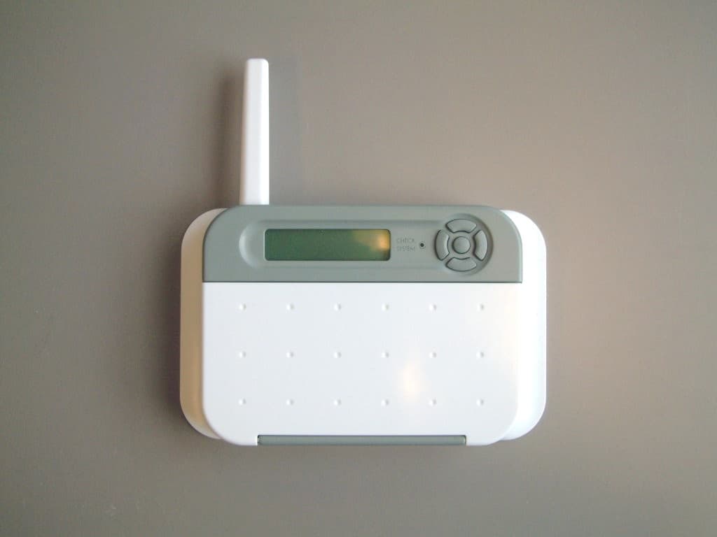
Click to zoom
Application Details
- Equipment Class
- DSS - Part 15 Spread Spectrum Transmitter
- Date of Grant
- Jan 24, 2007
- Application Purpose
- Original Equipment
- Date of Application
- Jan 24, 2007
- Equipment Note
- 902-927 MHz Frequency Hopping Radio Module
- Frequency Range
- 902.99970000 - 927.01450000
- Company
- Hayward Industries, Inc.
- Country
- United States
Documents & Files
Document Text
Text extracted from the exhibit documents filed with the FCC. Open a document above to read the original.
Users Manual
Questions? Refer to www.goldlinecontrols.com for latest manual revisions, additional information and helpful service. Or, you may visit your local Authorized Goldline Dealer or call 888-921-POOL (7665) for assistance. Aqua Pod Handheld Remote Control for Aqua LogicAqua Logic Aqua LogicAqua Logic Aqua Logic Automation and Chlorination Operation Manual Li Ion Battery DIsposal At the end of the batteries’ useful life, they must be recycled or disposed of properly. Contact your local county, or state hazardous waste management au- thorities for information on recycling or disposal programs in your area. FCC Statement This device complies with part 15 of the FCC rules. Operation is subject to the following two conditions: (1) This device may not cause harmful interference, and (2) this device must accept any interference received, including interference that may cause undesired operation. Changes or modifications not expressly approved by Goldline Controls could void the user’s authority to operate this equipment. NOTE: This equipment has been tested and found to comply with the limits for a Class B digital device, pursuant to Part 15 of the FCC Rules. These limits are designed to provide reasonable protection against harmful interference in a resi- dential installation. This equipment generates, uses and can radiate radio fre- quency energy and, if not installed and used in accordance with the instructions, may cause harmful interference to radio communications. However, there is no guarantee that interference will not occur in a particular installation. If this equip- ment does cause harmful interference to radio or television reception, which can be determined by turning the equipment off and on, the user is encouraged to try to correct the interference by one or more of the following measures: — Reorient or relocate the receiving antenna. — Increase the separation between the equipment and receiver. — Connect the equipment into an outlet on a circuit different from that to which the receiver is connected. — Consult the dealer or an experienced radio / TV technician for help. Industry Canada Statement This Class B digital apparatus complies with Canadian ICES-003. Cet appareil numérique de la classe B est conforme à la norme NMB-003 du Canada. The term “IC” before the certification / registration number only signifies that the Industry Canada technical specifications were met. www.goldlinecontrols.com 888-921-7665 North Kingstown, RI 02852 USA 092146A Copyright © 2006 Goldine Controls, Inc LD C G LINE ONTROLS LD C G LINE ONTROLS Compatibility This Aqua Pod handheld remote control is compatible with all Aqua Logic controls operating with software revision r2.60 or higher and using an AQL2-BASE-RF base station operating with software revision r3.00 or higher. Note that the Aqua Pod will NOT communicate with the AQL-BASE-RF base station. To verify the software level of your Aqua Logic control and base station, press the Menu button (possibly mul- tiple times) until "Diagnostic Menu" is displayed. Press the ">" or "<" keys (possibly multiple times) until the main software revision level is displayed (the revision should be 2.60 or higher). Next, press the ">" key (possibly multiple times) until the "RF Base" revision level is shown (the revision should be 3.00 or higher). If the software revision level is less than those specified above, contact the Goldline Technical Service Dept. from Monday through Friday, 8AM to 8PM Eastern at 888- 921-7665 for information on upgrades. Installation Installation The Aqua Pod uses a rechargeable built-in battery pack which will require an initial charge when you first receive the unit. Charge the Aqua Pod for at least 5 hours before attempting to use it without the charger. Note that the Aqua Pod can be used normally while connected to the charger. Installation of the Aqua Pod requires that you follow the steps below. 1.Batteries are installed at the factory: Do not attempt to open the Aqua Pod. 2.Base Station required: For operation of the Aqua Pod, the Aqua Logic control must have a base station (AQL2-BASE-RF) installed. The receiver allows the Aqua Logic control unit to communicate with the Aqua Pod remote. 3.Teach the unique Aqua Logic ID code: The base station attached to the Aqua Logic control has a unique ID code that ensures that your unit will not affect other systems in the neighborhood, and likewise, their remote will not affect your system. To teach the ID code to the Aqua Pod remote unit: a.On any Aqua Logic display/keypad unit press the “Menu” button (possibly multiple times) until “Settings Menu” is displayed. b.Press “<“ or “>” (again, possibly multiple times) until “Teach Wireless” is displayed. c.Press the “+” button to start the teaching process. d.Press and hold any button on the Aqua Pod remote for 4 seconds. The Aqua Logic dis- play should say “Teach Wireless, Success- ful”. 4.Installation is complete: you can now use the Aqua Pod remote. 1 Limited Warranty—Pool Automation & Chlorination Products 10/1/2004 This warranty statement is applicable to all pool automation and chlorination products manufactured by Goldline Controls, Inc. (Goldline) on or after October 1, 2004. See the appropriate warranty statement for other Goldline products or for pool automation and chlorination products produced prior to October 1, 2004. Aqua Rite/Trol/Logic—Residential pools in USA or Canada: Goldline warrants Aqua Rite, Aqua Trol, and Aqua Logic products (products with Goldline part numbers starting with AQ-RITE-, AQ-TROL-, AQ-LOGIC-, AQL-P-, AQL-PS-,or AQL-CL-) installed on private, residential swimming pools within the USA or Canada to be free from defects in material or workmanship, under normal use and service for five years from date of the initial system installation, provided it is installed in accordance with the Goldline installation instructions and specifications provided with the product. If written proof of the date of the initial system ins…
Text truncated - open the document above for the full version.
Users Manual
Aqua LogicAqua Logic Aqua LogicAqua Logic Aqua Logic Base Station Installation/Operation Manual for model AQL2-BASE-RF ® FCC Statement This device complies with part 15 of the FCC rules. Operation is subject to the following two conditions: (1) This device may not cause harmful interference, and (2) this device must accept any interference received, including interference that may cause undesired operation. Changes or modifications not expressly approved by Goldline Controls could void the user’s authority to operate this equipment. NOTE: This equipment has been tested and found to comply with the limits for a Class B digital device, pursuant to Part 15 of the FCC Rules. These limits are designed to provide reasonable protection against harmful interference in a resi- dential installation. This equipment generates, uses and can radiate radio fre- quency energy and, if not installed and used in accordance with the instructions, may cause harmful interference to radio communications. However, there is no guarantee that interference will not occur in a particular installation. If this equip- ment does cause harmful interference to radio or television reception, which can be determined by turning the equipment off and on, the user is encouraged to try to correct the interference by one or more of the following measures: — Reorient or relocate the receiving antenna. — Increase the separation between the equipment and receiver. — Connect the equipment into an outlet on a circuit different from that to which the receiver is connected. — Consult the dealer or an experienced radio / TV technician for help. Industry Canada Statement This Class B digital apparatus complies with Canadian ICES-003. Cet appareil numérique de la classe B est conforme à la norme NMB-003 du Canada. The term “IC” before the certification / registration number only signifies that the Industry Canada technical specifications were met. www.goldlinecontrols.com 888-921-7665 North Kingstown, RI 02852 USA 092047A Copyright © 2007 Goldine Controls, Inc LD C G LINE ONTROLS LD C G LINE ONTROLS Compatibility This product is compatible with all Aqua Logic controls operating software revision r1.10 or higher. To verify the software level of your Aqua Logic control: Press the Menu button (possibly multiple times) until “Diagnostic Menu” is displayed. Next, press the “>” or “<“ keys (possibly multiple times) until the main and display software revision levels are displayed (the “main” rev should be r1.10 or higher). If the software revision level is less than r1.10 contact the Goldline Technical Service Dept. from Monday through Friday, 8AM to 8PM Eastern at 888-921-7665 for informa- tion on upgrades. This Aqua Logic base station can communicate with the Aqua Logic spa-side remote (AQL2-SS-RF), the wireless wall mount and tabletop remote display/keypads (AQL2- Wx-RF-PS-x, AQL2-Tx-RF-PS-x) and the Aqua Pod handheld remote control (AQL2- POD). 16 proof of the date of the initial system installation is not provided to Goldline, the manufactur- ing datecode on the product or part will be the sole determinant of the date of the initial system installation. If a product is defective, in workmanship or materials and is removed and returned freight prepaid within one (1) year after the date of the initial system installation, Goldline will, at its option, either repair or replace the defective product and return it freight prepaid. The costs incurred in removal and/or reinstallation of the product are NOT covered under this warranty. Warranty exclusions: 1.Material supplied or workmanship performed by others in the process of installa- tion 2.Damage resulting from improper installation including installation on pools larger than the product rating. 3.Problems resulting from failure to operate the products in accordance with recom- mended instructions contained in product’s owners manual. 4.Problems resulting from failure to maintain pool water chemistry in accordance with recommended levels. 5.Problems resulting from tampering, accident, abuse, negligence, unauthorized repairs or alterations, fire, flood, lightning, freezing, external water, war, or acts of God. THE EXPRESS LIMITED WARRANTY ABOVE CONSTITUTES THE ENTIRE WAR- RANTY OF GOLDLINE CONTROLS, INC. WITH RESPECT TO ITS POOL AUTOMA- TION AND CHLORINATION PRODUCTS AND IS IN LIEU OF ALL OTHER WAR- RANTIES, EXPRESSED OR IMPLIED, INCLUDING WARRANTIES OF MERCHANT- ABILITY OR FITNESS FOR A PARTICULAR PURPOSE. IN NO EVENT SHALL GOLDLINE CONTROLS, INC. BE RESPONSIBLE FOR ANY CONSEQUENTIAL, SPE- CIAL OR INCIDENTAL DAMAGES OF ANY NATURE WHATSOEVER. NO WHOLESALER, AGENT, DEALER, CONTRACTOR, OR OTHER PERSON IS AU- THORIZED TO GIVE ANY WARRANTY ON BEHALF OF GOLDLINE CONTROLS, INC. THIS WARRANTY IS VOID IF THE PRODUCT HAS BEEN ALTERED IN ANY WAY AFTER LEAVING THE FACTORY. INSTALLATION Installation is very easy and should just take a few minutes. For most installations the Base Station will mount directly on the Aqua Logic main control unit (see description and diagram below). For some installations where the remote devices are a long distance from the Base Station or where there are interfering walls (eg. A steel shed in the yard or a steel reinforcing grid inside a stucco wall on the house), the Base Station may have to mounted remotely from the Aqua Logic control unit in order to achieve reliable communications. Refer to the instructions and diagram on page 3 for more information regarding remote mounting. Direct Mounting on Aqua Logic Control Unit Disconnect power and then remove the panel from the Aqua Logic control unit. Remove the knock-out on the upper left side of the Aqua Logic main unit and mount the RF base station. Secure the base station in place by firmly tightening the nut from inside the Aqua Logic unit. Lastly, plug the pigtail cable into the connector labeled “Wireless Connector” on the Aqua Logic main circuit board. 25 Limited Warranty Pool Automation & Chlorination Products 1/1/200…
Text truncated - open the document above for the full version.
Users Manual
Questions? Refer to www.goldlinecontrols.com for latest manual revisions, additional information and helpful service. Or, you may visit your local Authorized Goldline Dealer or call 888-921-POOL (7665) for assistance. Wireless Remote Display for Aqua LogicAqua Logic Aqua LogicAqua Logic Aqua Logic Automation and Chlorination Installation/Operation Manual for blackwhitegray AQL2-WB-RF-PS-4AQL2-WW-RF-PS-4AQL2-WG-RF-PS-4 AQL2-WB-RF-PS-8AQL2-WW-RF-PS-8AQL2-WG-RF-PS-8 AQL2-WB-RF-PS-16AQL2-WW-RF-PS-16AQL2-WG-RF-PS-16 blackwhitegray AQL2-TB-RF-PS-4AQL2-TW-RF-PS-4AQL2-TG-RF-PS-4 AQL2-TB-RF-PS-8AQL2-TW-RF-PS-8AQL2-TG-RF-PS-8 AQL2-TB-RF-PS-16AQL2-TW-RF-PS-16AQL2-TG-RF-PS-16 NICAD BATTERY DISPOSAL (AQL-Tx-RF-PS-x models) At the end of the batteries’ useful life, they must be recycled or disposed of properly. Contact your local county, or state hazardous waste management au- thorities for information on recycling or disposal programs in your area. FCC Statement This device complies with part 15 of the FCC rules. Operation is subject to the following two conditions: (1) This device may not cause harmful interference, and (2) this device must accept any interference received, including interference that may cause undesired operation. Changes or modifications not expressly approved by Goldline Controls could void the user’s authority to operate this equipment. NOTE: This equipment has been tested and found to comply with the limits for a Class B digital device, pursuant to Part 15 of the FCC Rules. These limits are designed to provide reasonable protection against harmful interference in a resi- dential installation. This equipment generates, uses and can radiate radio fre- quency energy and, if not installed and used in accordance with the instructions, may cause harmful interference to radio communications. However, there is no guarantee that interference will not occur in a particular installation. If this equip- ment does cause harmful interference to radio or television reception, which can be determined by turning the equipment off and on, the user is encouraged to try to correct the interference by one or more of the following measures: — Reorient or relocate the receiving antenna. — Increase the separation between the equipment and receiver. — Connect the equipment into an outlet on a circuit different from that to which the receiver is connected. — Consult the dealer or an experienced radio / TV technician for help. Industry Canada Statement This Class B digital apparatus complies with Canadian ICES-003. Cet appareil numérique de la classe B est conforme à la norme NMB-003 du Canada. The term “IC” before the certification / registration number only signifies that the Industry Canada technical specifications were met. www.goldlinecontrols.com 888-921-7665 North Kingstown, RI 02852 USA 092046A Copyright © 2004 Goldine Controls, Inc Wall Mount models: Table Top models: wall mount model LD C G LINE ONTROLS LD C G LINE ONTROLS table top model Compatibility This product is compatible with all Aqua Logic PS controls operating with software revision r2.00 or higher and using an AQL2-BASE-RF base station operating with software revision r3.00 or higher. Note that this product will NOT communicate with the AQL-BASE-RF base station. To verify the software level of your Aqua Logic control, press the Menu button (possibly multiple times) until "Diagnostic Menu" is displayed. Press the ">" or "<" keys (possibly multiple times) until the main software revision level is displayed (the revision should be 2.00 or higher). Next, press the ">" key (possibly multiple times) until the "RF Base" revision level is shown (the revision should be 3.00 or higher). If the software revision level is less than those specified above, contact the Goldline Technical Service Dept. from Monday through Friday, 8AM to 8PM Eastern at 888- 921-7665 for information on upgrades. Installation Installation - AQL2-Wx-RF-PS-x Wall Mount models 1.Base Receiver required: For operation of the AQL2-Wx-RF-PS-x, the Aqua Logic control unit must have an AQL2-BASE-RF base receiver installed. Note that this unit will NOT operate with the AQL-BASE-RF base receiver. 2.Select Location: There are several considerations in choosing the location for the wireless remote display/keypad: Protected from the weather: The wireless remote display/keypad must be mounted indoors or in a weather protected area (rain should never hit the wireless remote display/keypad). The wireless remote display/keypad is designed to mount onto a standard electrical utility box (same size as used for a triple light switch) or can be mounted directly onto any wall surface. Within range of Base Receiver: The wireless remote display/keypad must be installed within 200 ft. (assuming the signal will have to travel through walls) or 400 ft. (line of sight) from the Base Receiver which is typically mounted on the Aqua Logic main control unit at the pool equipment pad. The Base Receiver can also be mounted up to 500 ft. away from the main control unit to shorten the distance between it and any wireless remote. See the "Remote Mounting of the Base Receiver" section of the Base Receiver manual for more details. Near 120V wall outlet: The wireless remote display/keypad uses a plug-in power supply with a 6 ft. cable. 3.Mount on wall: The wireless remote display/keypad must be mounted indoors or in a weather protected area (rain should never hit the display/keypad). Refer to the diagram on the following page. a.Remove display/keypad baseplate from the cover by inserting a screwdriver in the slot shown below. Lift up on the cover while pushing gently with the screwdriver. See Fig. 1. b.Thread the wall mount power supply’s output connector from behind and through the opening in the left side of the baseplate. See Fig. 2. 1 10 c.Screw the baseplate in the desired position (screws supplied by installer). d.Plug the power supply’s output connector into the mating connector on the back of the AQL2…
Text truncated - open the document above for the full version.
Cover Letter(s)
Rhein Tech Laboratories, Inc. Client: Goldline Controls, Inc. 360 Herndon Parkway Model #: G1-011024 & G1-011029 Suite 1400 Standards: FCC 15.247 & RSS-210 ID’s: RNW-MD-FH-09-01 & 5110A-MDFH0901 Herndon, VA 20170 http://www.rheintech.com Report #: 2006167 Appendix B: Agency Authorization Letter Please refer to the following page.
Cover Letter(s)
Rhein Tech Laboratories, Inc. Client: Goldline Controls, Inc. 360 Herndon Parkway Model #: G1-011024 & G1-011029 Suite 1400 Standards: FCC 15.247 & RSS-210 ID’s: RNW-MD-FH-09-01 & 5110A-MDFH0901 Herndon, VA 20170 http://www.rheintech.com Report #: 2006167 Appendix C: Confidentiality Request Letter Please refer to the following page.
Cover Letter(s)
Rhein Tech Laboratories, Inc. Client: Goldline Controls, Inc. 360 Herndon Parkway Model #: G1-011024 & G1-011029 Suite 1400 Standards: FCC 15.247 & RSS-210 ID’s: RNW-MD-FH-09-01 & 5110A-MDFH0901 Herndon, VA 20170 http://www.rheintech.com Report #: 2006167 Appendix E: FCC Modular Approval Request Please refer to the following pages. 11/16/2006 Federal Communications Commission 7435 Oakland Mills Road Columbia, MD 21046-1609 To Whom It May Concern: In reference to the application for FCC ID#: RNW-MD-FH-09-01 Generation II FHSS radio module, this device is being submitted for limited MODULAR TRANSMITTER APPROVAL based on the guidelines in FCC Publication DA 00-1407. We believe that this transmitter meets all 8 criterion listed in DA 00-1407 as detailed in the paragraphs below. 1) RNW-MD-FH-09-01 does not contain a metallic shield over the RF portion of the circuitry, but does contain a layer of broadband microwave absorber material. All testing performed showed that the addition of a metallic shield made no significant improvement to radiated emissions performance, while the addition of the microwave absorber made a significant improvement. Further, all finished devices in which this radio will be mounted will be subjected to Part 15.209 radiated emissions testing to Class B. 2) RNW-MD-FH-09-01 has fully buffered inputs on all digital lines. Overdriving one or more of the digital inputs will have no affect on the transmitter output. 3) RNW-MD-FH-09-01 contains a linear voltage regulator that powers the transmitter as well as all other circuitry on the module. The module is designed to accept between 4 and 26 volts DC at it’s input, which is then regulated down to 3.3 volts DC. If the input voltage were to be exceeded this would cause the linear regulator to overheat while still maintaining regulation, up to the point where the pass transistor fails and voltage to the transmitter is cut off. The transmitter output will not be affected if input voltage is exceeded. Further, since the module will only be used in Goldline products, Goldline has full control of the power supply to the module and will insure that the correct voltage is provided to the module. 4) RNW-MD-FH-09-01 will always be used with one of a family of approved antennas, which are permanently mounted (along with the radio) inside of a finished product. The antennas are not user accessible in the completed product. There is one configuration (wall mount AQL2 terminal) in which the device is
Cover Letter(s)
American Telecommunications Certification Body Inc. 6731 Whittier Ave, McLean, VA 22101 January 17, 2007 RE: Goldline Controls Inc. FCC ID: RNW-MD-FH-09-01 I have a few comments on this Application. 1 The system receivers shall have input bandwidths that match the hopping channel bandwidths of their corresponding transmitters and shall shift frequencies in synchronization with the transmitted signals see CFR Part 15.247(a)(1). Please confirm this is the case and submit in confirmation letter. Response: Please refer to the attestation letter uploaded with this response, which also addresses the comments in #2. 2 Please review CFR 15.247(g)(h) and confirm that the unit complies with these part of the rules and include with confirmation letter. Response : Please refer to the attestation letter uploaded with this response, which also addresses the comments in #1. 3 Please provide a pseudo random hopping frequency list showing hopping order of all 75 hopping frequencies. Response : Please refer to the revised operational description exhibit uploaded with this response, for this proprietary information. 4 Industry Canada requires the manufacturer name, model number and the IC: number be on the labels according to RSS-GEN Section 5.2. Please revise the label to comply. Response : Please review the revised label exhibit uploaded with this response. Douglas E. Noble Examining Engineer mailto: [email protected] The items indicated above must be submitted before processing can continue on the above referenced application. Failure to provide the requested information may result in application termination. Correspondence should be considered part of the permanent submission and may be viewed from the Internet after a Grant of Equipment Authorization is issued. Please do not respond to this correspondence using the email reply button. In order for your response to be processed expeditiously, you must submit your documents through the AmericanTCB.com website. Also, please note that partial responses increase processing time and should not be submitted. Any questions about the content of this correspondence should be directed to the sender.
External Photos
Rhein Tech Laboratories, Inc. Client: Goldline Controls, Inc. 360 Herndon Parkway Model #: G1-011024 & G1-011029 Suite 1400 Standards: FCC 15.247 & RSS-210 ID’s: RNW-MD-FH-09-01 & 5110A-MDFH0901 Herndon, VA 20170 http://www.rheintech.com Report #: 2006167 Appendix M: External Photographs Photograph 5: Base Station Front View Rhein Tech Laboratories, Inc. Client: Goldline Controls, Inc. 360 Herndon Parkway Model #: G1-011024 & G1-011029 Suite 1400 Standards: FCC 15.247 & RSS-210 ID’s: RNW-MD-FH-09-01 & 5110A-MDFH0901 Herndon, VA 20170 http://www.rheintech.com Report #: 2006167 Photograph 6: Base Station Rear View Rhein Tech Laboratories, Inc. Client: Goldline Controls, Inc. 360 Herndon Parkway Model #: G1-011024 & G1-011029 Suite 1400 Standards: FCC 15.247 & RSS-210 ID’s: RNW-MD-FH-09-01 & 5110A-MDFH0901 Herndon, VA 20170 http://www.rheintech.com Report #: 2006167 Photograph 7: AquaPod Front View Rhein Tech Laboratories, Inc. Client: Goldline Controls, Inc. 360 Herndon Parkway Model #: G1-011024 & G1-011029 Suite 1400 Standards: FCC 15.247 & RSS-210 ID’s: RNW-MD-FH-09-01 & 5110A-MDFH0901 Herndon, VA 20170 http://www.rheintech.com Report #: 2006167 Photograph 8: AquaPod Rear View Rhein Tech Laboratories, Inc. Client: Goldline Controls, Inc. 360 Herndon Parkway Model #: G1-011024 & G1-011029 Suite 1400 Standards: FCC 15.247 & RSS-210 ID’s: RNW-MD-FH-09-01 & 5110A-MDFH0901 Herndon, VA 20170 http://www.rheintech.com Report #: 2006167 Photograph 9: AQL Tabletop Front View Rhein Tech Laboratories, Inc. Client: Goldline Controls, Inc. 360 Herndon Parkway Model #: G1-011024 & G1-011029 Suite 1400 Standards: FCC 15.247 & RSS-210 ID’s: RNW-MD-FH-09-01 & 5110A-MDFH0901 Herndon, VA 20170 http://www.rheintech.com Report #: 2006167 Photograph 10: AQL Tabletop Rear View Rhein Tech Laboratories, Inc. Client: Goldline Controls, Inc. 360 Herndon Parkway Model #: G1-011024 & G1-011029 Suite 1400 Standards: FCC 15.247 & RSS-210 ID’s: RNW-MD-FH-09-01 & 5110A-MDFH0901 Herndon, VA 20170 http://www.rheintech.com Report #: 2006167 Photograph 11: AQL Wall Mount
ID Label/Location Info
Rhein Tech Laboratories, Inc. Client: Goldline Controls, Inc. 360 Herndon Parkway Model #: G1-011024 & G1-011029 Suite 1400 Standards: FCC 15.247 & RSS-210 ID’s: RNW-MD-FH-09-01 & 5110A-MDFH0901 Herndon, VA 20170 http://www.rheintech.com Report #: 2006167 Appendix G: Label and Label Location Please refer to the following pages for a sample of the labels and label locations. Base Station ID Label Base Station Label Location AQL2 Terminal ID Label AQL2 Table Top Label Location AQL2 Wall Mount Label Location 3101970 Contains FCC ID: RNW-MD-FH-09-01 Contains IC: 5 G1-011029 110A-MDFH0901 3101970 Contains FCC ID: RNW-MD-FH-09-01 Contains IC: 5 G1-011029 110A-MDFH0901 Contains FCC ID: RNW-MD-FH-09-01 Contains IC: 5 G1-011029 110A-MDFH0901 3101970 AquaPod ID Label AquaPod Label Location
Internal Photos
Rhein Tech Laboratories, Inc. Client: Goldline Controls, Inc. 360 Herndon Parkway Model #: G1-011024 & G1-011029 Suite 1400 Standards: FCC 15.247 & RSS-210 ID’s: RNW-MD-FH-09-01 & 5110A-MDFH0901 Herndon, VA 20170 http://www.rheintech.com Report #: 2006167 Appendix N: Internal Photographs Photograph 12: Module PCB Top with Absorber Rhein Tech Laboratories, Inc. Client: Goldline Controls, Inc. 360 Herndon Parkway Model #: G1-011024 & G1-011029 Suite 1400 Standards: FCC 15.247 & RSS-210 ID’s: RNW-MD-FH-09-01 & 5110A-MDFH0901 Herndon, VA 20170 http://www.rheintech.com Report #: 2006167 Photograph 13: Module PCB Top Rhein Tech Laboratories, Inc. Client: Goldline Controls, Inc. 360 Herndon Parkway Model #: G1-011024 & G1-011029 Suite 1400 Standards: FCC 15.247 & RSS-210 ID’s: RNW-MD-FH-09-01 & 5110A-MDFH0901 Herndon, VA 20170 http://www.rheintech.com Report #: 2006167 Photograph 14: Module PCB Bottom Rhein Tech Laboratories, Inc. Client: Goldline Controls, Inc. 360 Herndon Parkway Model #: G1-011024 & G1-011029 Suite 1400 Standards: FCC 15.247 & RSS-210 ID’s: RNW-MD-FH-09-01 & 5110A-MDFH0901 Herndon, VA 20170 http://www.rheintech.com Report #: 2006167 Photograph 15: Module PCB with Absorber on Base Station PCB Photograph 16: Module PCB on Base Station PCB Rhein Tech Laboratories, Inc. Client: Goldline Controls, Inc. 360 Herndon Parkway Model #: G1-011024 & G1-011029 Suite 1400 Standards: FCC 15.247 & RSS-210 ID’s: RNW-MD-FH-09-01 & 5110A-MDFH0901 Herndon, VA 20170 http://www.rheintech.com Report #: 2006167 Photograph 17: Base Station PCB Bottom Rhein Tech Laboratories, Inc. Client: Goldline Controls, Inc. 360 Herndon Parkway Model #: G1-011024 & G1-011029 Suite 1400 Standards: FCC 15.247 & RSS-210 ID’s: RNW-MD-FH-09-01 & 5110A-MDFH0901 Herndon, VA 20170 http://www.rheintech.com Report #: 2006167 Photograph 18: Module with Absorber on AquaPod PCB Rhein Tech Laboratories, Inc. Client: Goldline Controls, Inc. 360 Herndon Parkway Model #: G1-011024 & G1-011029 Suite 1400 Standards: FCC 15.247 & RSS-210 ID’s: RNW-MD-FH-09-01 & 5110A-MDFH0901 Herndon, VA 20170 http://www.rheintech.com Report #: 2006167 Photograph 19: Module with Absorber on AQL Terminal
RF Exposure Info
Rhein Tech Laboratories, Inc. Client: Goldline Controls, Inc. 360 Herndon Parkway Model #: G1-011024 & G1-011029 Suite 1400 Standards: FCC 15.247 & RSS-210 ID’s: RNW-MD-FH-09-01 & 5110A-MDFH0901 Herndon, VA 20170 http://www.rheintech.com Report #: 2006167 Appendix A: RF Exposure Compliance No RF Exposure Evaluation Required if power is below the following threshold: Tunable Range f(GHz) Low f(GHz) High Center of Tunable Band (GHz) 60/f SAR Limitation (mW) 0.903 0.927 0.915 65.6 Maximum measured transmitter power: Pout Conducted (mW) Maximum Antenna Gain (numeric) Pout EIRP (mW) 6 0.53 3.2 6 1.15 6.9 6 1.32 7.9 Threshold at which no RF exposure evaluation is 65.6 mW. Maximum TX Power is 6 mW Conducted and 7.9 mW EIRP. Conclusion: No RF exposure evaluation is required since the maximum Transmitter Pout (both conducted and EIRP) is below the FCC threshold.
Test Setup Photos
Rhein Tech Laboratories, Inc. Client: Goldline Controls, Inc. 360 Herndon Parkway Model #: G1-011024 & G1-011029 Suite 1400 Standards: FCC 15.247 & RSS-210 ID’s: RNW-MD-FH-09-01 & 5110A-MDFH0901 Herndon, VA 20170 http://www.rheintech.com Report #: 2006167 Appendix L: Test Photographs Photograph 1: Radiated Emissions Testing Front View Rhein Tech Laboratories, Inc. Client: Goldline Controls, Inc. 360 Herndon Parkway Model #: G1-011024 & G1-011029 Suite 1400 Standards: FCC 15.247 & RSS-210 ID’s: RNW-MD-FH-09-01 & 5110A-MDFH0901 Herndon, VA 20170 http://www.rheintech.com Report #: 2006167 Photograph 2: Radiated Emissions Testing Back View Rhein Tech Laboratories, Inc. Client: Goldline Controls, Inc. 360 Herndon Parkway Model #: G1-011024 & G1-011029 Suite 1400 Sta…
Text truncated - open the document above for the full version.
Contact Information
Applicant
John O'Hare(Senior Manager Product Compliance)
Technical Contact
Rhein Tech LabsDesmond Frazer
[email protected]703-689-0368
360 Herndon Parkway · Herndon, Virginia · United States
Test Firm
Rhein Tech Laboratories, Inc.Rick McMurray
Technical Specifications
| # | Rule Parts | Frequency Range | Power Output |
|---|---|---|---|
| 1 | 15C | 902.9997 MHz - 927.0145 MHz | 6.00 mW |
Other Applications from Hayward Industries, Inc.
RNW-AQL-RF-PS-XX
Oct 05, 2004Wireless Remote Display
Equipment Class
DXX - Part 15 Low Power Communication Device Transmitter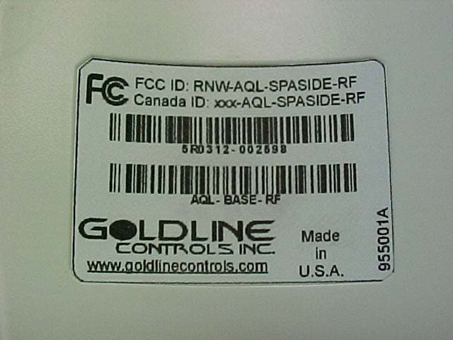
RNW-AQLSPASIDE-RF
Feb 11, 2004Remote Control
Equipment Class
DXX - Part 15 Low Power Communication Device Transmitter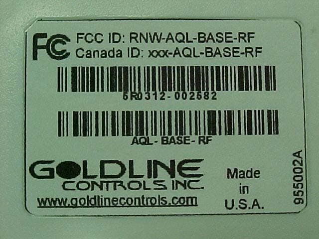
RNW-AQL-BASE-RF
Feb 11, 2004RF Base Station
Equipment Class
DXX - Part 15 Low Power Communication Device Transmitter