RNW-AQLSPASIDE-RFRemote Control
Hayward Industries, Inc.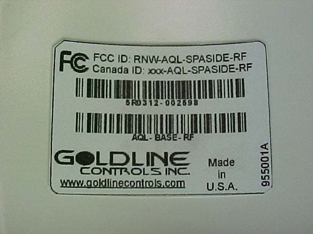
Click to zoom
Application Details
- Equipment Class
- DXX - Part 15 Low Power Communication Device Transmitter
- Date of Grant
- Feb 11, 2004
- Application Purpose
- Original Equipment
- Date of Application
- Feb 11, 2004
- Equipment Note
- Remote Control
- Frequency Range
- 902.00000000 - 928.00000000
- Company
- Hayward Industries, Inc.
- Country
- United States
Documents & Files
Document Text
Text extracted from the exhibit documents filed with the FCC. Open a document above to read the original.
Users Manual
Aqua LogicAqua Logic Aqua LogicAqua Logic Aqua Logic Spa-side Remote Installation/Operation Manual for model AQL-SPASIDE-RF LDLINE CONTROLS INC. G North Kingstown, RI USA www.goldlinecontrols.com ® Compatibility This product is compatible with all Aqua Logic controls operating with software revi- sion r1.10 or higher. To verify the software level of your Aqua Logic control, press the Menu button (possibly multiple times) until “Diagnostic Menu” is displayed. Next, press the “>” or “<“ keys (possibly mulitple times) until the main and display soft- ware revision levels are displayed (the “main” rev should be r1.10 or higher). If the software revision level is less than r1.10 contact the Goldline Technical Service Dept. from Monday through Friday, 8AM to 8PM Eastern at 888-921-7665 for infor- mation on upgrades. Installation 1.Batteries are installed at the factory: There is no need to open the spa-side unit. 2.Base Receiver required: For operation of the spa-side remote, the Aqua Logic control unit must have a base receiver (AQL-BASE-RF) installed. The receiver allows the Aqua Logic control until to communicate with the spa-side remote. 3.Teach the unique Aqua Logic ID code: The base receiver attached to the Aqua Logic control unit has a unique ID code that ensures that your unit will not affect other systems in the neighborhood, and likewise, their remote will not affect your system. To teach the ID code to the spa-side remote unit: a.On any Aqua Logic display/keypad unit press the “Menu” button (possibly multiple times) until “Settings Menu” is displayed. b.Press “<“ or “>” (again, possibly multiple times) until “Teach Wireless” is displayed. c.Press the “+” button to start the teaching process. d.Press and hold any button on the spa-side remote for 4 seconds. At this point the LED indicator on the spa-side remote should flash 3 times and the Aqua Logic display should say “Teach Wireless, Successful”. If the LED indicator does not flash, then refer to the Troubleshooting section of this manual for additional information. 4.Apply labels: Aqua Logic PS series of control allow each output (e.g. AUX1) to be re-named to what is actually being controlled. The spa-side remote comes with a sheet of name labels—simply peel the appropriate label off the sheet and apply to the appropriate set of buttons on the spa-side remote. 5.Installation is complete: you can now use the spa-side wireless remote. Settings Menu Teach Wireless: + to start Teach Wireless: Sucessful Press and hold wireless button 1 Operation The spa-side remote communicates with the base receiver on the Aqua Logic control unit using RF (radio frequency) technology. When you push a button on the spa-side remote, it sends a command and flashes the LED indicator once. After the spa-side remote receives a confirmation from the Aqua Logic base the receiver, the LED indi- cator on the spa-side remote flashes a 2 nd time. Thus, 2 LED flashes are your confir- mation that your command has been successfully transmitted to the Aqua Logic con- trol unit. If the LED doesn’t flash at all or else just flashes once after you’ve pushed a button, refer to the Troubleshooting section for assistance in resolving these prob- lems. Valves POOL/SPAThese buttons will allow you to select either pool or spa opera- tion. You can not select spa spillover operation from the spa- side remote. Filter ON/OFFThe ON/OFF buttons allow manual operation that will override any automatic control settings (e.g. timeclock). The manual setting will remain active until the next scheduled automatic turn on/off event. There are some exceptions: If the heater is operating and the heater cooldown function is enabled, then pressing the OFF button will turn off the heater and the pump will run for another 15 minutes to allow the heater to cooldown before automatically turning off If the freeze protection feature is enabled and the air tempera- ture is below 38°F, then the pump will remain on to ensure that the pipes do not freeze. 2 LDLINE CONTROLS INC. G POOL SPA ON OFF ON OFF ON OFF ON OFF ON OFF VALVES FILTER HEATER LIGHTS AUX1 AUX2 Heater ON/OFFProvided that the filter pump is running, normal Aqua Logic operation will turn the heater on until the desired temperature (see Settings Menu) is attained. The heater will then turn on periodically, as required, to maintain that temperature. When the ON button is pushed, the heater will turn on for a minimum of 5 minutes or until the water reaches 104°F This allows people in the spa to temporarily override the normal temperature set- ting. When the OFF button is pushed, the heater is turned off regardless of the water temperature and will remain off until ei- ther the ON button is pressed, or the start of the next normal filter timer period. Lights ON/OFFThe ON/OFF buttons allow manual operation that will override any automatic control settings (e.g. timeclock). The manual set- ting will remain active until the next scheduled automatic turn on/off event. Aux1 ON/OFF Aux2 ON/OFFThe ON/OFF buttons allow manual operation that will override any automatic control settings (e.g. timeclock). The manual set- ting will remain active until the next scheduled automatic turn on/off event. Battery Replacement The spa-side remote runs on two AAA batteries. Since the internal circuits are only active when you push a button, it is anticipated that the original, factory-installed, batteries should provide years of service. If you do not at least see a single flash of the LED indicator when you push a button, then the batteries may need replacement. It is IMPORTANT that you carefully follow this procedure to ensure that your spa- side remote retains its watertight integrity: 1.Use a Phillips head screwdriver to remove the 4 screws on the back of the spa- side remote. These are special screws with built-in o-rings and are an important part of making the spa-side remote watertight. 2.Separate the 2 halves of the remote. Do not touch the o-rings or allow …
Text truncated - open the document above for the full version.
Cover Letter(s)
42 Ladd Street, East Greenwich, RI 02818 Tel: 800-343-0826 / 401-884-6990 Fax: 401-885-1500 www.goldlinecontrols.com F C C CONFIDENTIALITY Date: 11/20/03 To: FEDERAL COMMUNICATIONS COMMISSION 7435 Oakland Mills Road Columbia, MD 21046 Subject: Request for Non disclosure for FCC ID: RNW - AQLSPASIDE-RF . To Whom It May Concern: Pursuant to 47 CFR Section 0.459, _Goldline Controls, Inc. hereby requests non disclosure and confidential treatment of the following materials submitted in support of FCC certification application for FCC ID # ( RNW - AQLSPASIDE-RF ) a. Schematic Diagrams b. Operational Description c. Block Diagram Above materials contain trade secrets, proprietary and technical information which would customarily be guarded from competitors under 47 CFR section 0.457(d)(2). Disclosure or publication of any portion of this company confidential material to other parties could cause substantial competitive harm and provide unjustified benefits for competitors. Goldline Controls, Inc. understands that pursuant to 47 CFR section 0.457(d)(1)(ii) disclosure of the applicant and all accompanying documentation will not be made before the date of the grant. Sincerely yours, Charles Savoie Engineering Manager Goldline Controls, Inc.
Cover Letter(s)
Response to TCB Findings 1. Please supply plots/data showing that the lowest and highest channels meet the 15.209 band-edges. Band-edge plots included in the revised test report.
External Photos
Goldline Controls Incorporated AquaLogic Spa-side Remote Control 902 – 926 MHz Radio FCC ID#: RNW-AQLSPASIDE-RF Photo One – External Hand Held Spa Controller Transceiver Goldline Controls Incorporated AquaLogic Spa-side Remote Control 902 – 926 MHz Radio FCC ID#: RNW-AQLSPASIDE-RF Photo Two – External Hand Held Spa Controller Transceiver – FCC Label Goldline Controls Incorporated AquaLogic Spa-side Remote Control 902 – 926 MHz Radio FCC ID#: RNW-AQLSPASIDE-RF Photo Three – External Hand Held Spa Controller Transceiver – FCC Label Close Up
Internal Photos
Goldline Controls Incorporated AquaLogic Spa-side Remote Control 902 – 926 MHz Radio FCC ID#: RNW-AQLSPASIDE-RF Photo Four – Internal Hand Held Spa Controller Open for Inspection Goldline Controls Incorporated AquaLogic Spa-side Remote Control 902 – 926 MHz Radio FCC ID#: RNW-AQLSPASIDE-RF Photo Five – Internal Hand Held Spa Controller Open for Inspection Key Board Contacts Goldline Controls Incorporated AquaLogic Spa-side Remote Control 902 – 926 MHz Radio FCC ID#: RNW-AQLSPASIDE-RF Photo Six – Internal Hand Held Spa Controller Open for Inspection Key Board PCB Close Up Goldline Controls Incorporated AquaLogic Spa-side Remote Control 902 – 926 MHz Radio FCC ID#: RNW-AQLSPASIDE-RF Photo Seven – Internal Hand Held Spa Controller Open for Inspection Key Board PCB RF Section Close Up Goldline Controls Incorporated AquaLogic Spa-side Remote Control 902 – 926 MHz Radio FCC ID#: RNW-AQLSPASIDE-RF Photo Eight – Internal Hand Held Spa Controller Open for Inspection Key Board PCB Flip Side Goldline Controls Incorporated AquaLogic Spa-side Remote Control 902 – 926 MHz Radio FCC ID#: RNW-AQLSPASIDE-RF Photo Nine – Internal Hand Held Spa Controller Open for Inspection Key Board PCB Flip Side RF Section Close Up Goldline Controls Incorporated AquaLogic Spa-side Remote Control 902 – 926 MHz Radio FCC ID#: RNW-AQLSPASIDE-RF Photo Ten – Internal Hand Held Spa Controller Open for Inspection Key Board PCB Flip Side RF Section Close Up with PCB Antenna
Test Report
L.S. Compliance, Inc. W66 N220 Commerce Court Cedarburg, WI 53012 262-375-4400 Fax: 262-375-4248 COMPLIANCE TESTING OF: AquaLogic RF Controller PREPARED FOR: Goldline Controls, Incorporated Attn.: Mr. Charles Savoie 42 Ladd Street East Greenwich, RI 02818 TEST REPORT NUMBER: 303458-TX Rev. 1 TEST DATE(S): December 7 th , 2003 All results of this report relate only to the items that were tested. This report is not to be reproduced, except in full, without written approval of L. S. Compliance, Inc. L.S. Compliance, Inc. Page 2 of 21 Test Report Number: 303458-TX Rev. 1 Prepared For: Goldline Controls Table of Contents Section Description Page Index 2 1 L. S. Compliance in Review 3 2 A2LA Certificate of Accreditation 4 3 A2LA Scope of Accreditation 5 4 Validation Letter-U.S. Competent Body for EMC Directive 89/336/EEC 6 5 Signature Page 7 6 Product and General Information 8 7 Product Description 8 8 Test Requirements 9 9 Declaration of Conformity 9 10 Introduction 9 11 Purpose 9 12 Radiated Emissions Test 10-17 13 Conducted Emissions Test (AC Power Line) 18 14 Band Edge Measurements 19 15 Frequency and Power Stability versus Voltage 20 Appendix A Test Equipment List 21 L.S. Compliance, Inc. Page 3 of 21 Test Report Number: 303458-TX Rev. 1 Prepared For: Goldline Controls 1. L. S. Compliance In Review Brief Review of L.S. Compliance Accreditations and Listing’s As an EMC Testing Laboratory, our Accreditation and Assessments are recognized through the following: A2LA – American Association for Laboratory Accreditation Accreditation based on ISO/IEC 17025 : 1999 with Electrical (EMC) Scope of Accreditation A2LA Certificate Number: 1255.01 Federal Communications Commission (FCC) – USA Listing of 3 Meter Semi-Anechoic Chamber based on Title 47 CFR – Part 2.948 FCC Registration Number: 90756 Listing of 3 and 10 meter OATS based on Title 47CFR – Part 2.948 FCC Registration Number: 90757 Industry Canada On file, 3 Meter Semi-Anechoic Chamber based on RSS-212 – Issue 1 File Number: IC 3088-A On file, 3 and 10 Meter OATS based on RSS-212 – Issue 1 File Number: IC 3088 U. S. Conformity Assessment Body (CAB) Validation Validated by the European Commission as a U. S. Competent Body operating under the U. S. /EU, Mutual Recognition Agreement (MRA) operating under the European Union Electromagnetic Compatibility –Council Directive 89/336/EEC, Article 10.2. Date of Validation: January 16, 2001 Validated by the European Commission as a U.S. Notified Body operating under the U.S./EU, Mutual Recognition Agreement (MRA) operating under the European Union Telecommunication Equipment – Council Directive 99/5/EC, Annex V. Date of Validation: November 20, 2002 Notified Body Identification Number: 1243 L.S. Compliance, Inc. Page 4 of 21 Test Report Number: 303458-TX Rev. 1 Prepared For: Goldline Controls 2. A2LA Certificate of Accreditation L.S. Compliance, Inc. Page 5 of 21 Test Report Number: 303458-TX Rev. 1 Prepared For: Goldline Controls 3. A2LA Scope of Accreditation L.S. Compliance, Inc. Page 6 of 21 Test Report Number: 303458-TX Rev. 1 Prepared For: Goldline Controls 4. Validation Letter – U.S. Competent Body for EMC Directive 89/336/EEC L.S. Compliance, Inc. Page 7 of 21 Test Report Number: 303458-TX Rev. 1 Prepared For: Goldline Controls 5. Signature Page Prepared By: January 23, 2004 Teresa A. White, Document Coordinator Date Tested By: January 23, 2004 Abtin Spantman, EMC Engineer Date Approved By: January 23, 2004 Kenneth L. Boston, EMC Lab Manager Date PE #31926 Licensed Professional Engineer Registered in the State of Wisconsin, United States L.S. Compliance, Inc. Page 8 of 21 Test Report Number: 303458-TX Rev. 1 Prepared For: Goldline Controls 6. Product and General Information Manufacturer: Goldline Controls, Incorporated Model No.: Aqua Logic Controller Serial No.: Engineering Unit # 302 Description: Wireless Remote Spa Controller 7. Product Description The Goldline AquaLogic RF Remote Controller provides a remote wireless solution for a Spa controller system. The system is composed of a “Base Unit” containing the transceiver and control circuitry for the Spa, and a “Remote Controller Unit” containing a transceiver and keypad. The base and remote units comprise a remote control system that utilizes a 5 channel scanning scheme to obtain a clear channel. Base receiver will continuously scan 5 channels for a signal from the remote. The remote is normally in sleep mode and wakes up and transmits upon keypad activation. The RF design is based upon the ‘Chipcon’ CC1020 transceiver IC (half-duplex) for operation in the 902-928 ISM band. The system uses Manchester-encoded binary data at 9600 bps, frequency modulated with a 19.8 kHz peak to peak deviation. The base unit is powered from an external power supply source providing 10 volts DC, which is then regulated to 3.3 VDC internally. The system uses a frequency modulation technique, and is capable of utilizing 25 different frequency channels in the 902-928 MHz band. Three channels were selected for testing: Set 1, channel 1 (902.5 MHz), set 3, channel 3 (914.5 MHz), and set 5, channel 5 (926.5 MHz). The channel and sets are defined as follows: Channel Set Channel Set 1 Set 2 Set 3 Set 4 Set 5 1 902.5 903.5 904.5 905.5 906.5 2 907.5 908.5 909.5 910.5 911.5 3 912.5 913.5 914.5 915.5 916.5 4 917.5 918.5 919.5 920.5 921.5 5 922.5 923.5 924.5 925.5 926.5 MHz MHz MHz MHz MHz L.S. Compliance, Inc. Page 9 of 21 Test Report Number: 303458-TX Rev. 1 Prepared For: Goldline Controls 8. Test Requirements The tests were performed in order to determine the compliance of the Goldline AquaLogic RF Remote Controller with limits contained in various provisions of Title 47 CFR, FCC Part 15, including 15.109, 15.205, 15.207, and 15.249. All radiated emissions tests were performed to measure the emissions in the frequency bands described by the above sections, and to determine whether said emissions are below the limits established by the above sections. These tests were perf…
Text truncated - open the document above for the full version.
Test Setup Photos
Photos Taken During Radiated Emission Testing EUT in Horizontal Orientation EUT in Vertical Orientation EUT on Side Orientation
Contact Information
Applicant
John O'Hare(Senior Manager Product Compliance)
Test Firm
LS Research, LLCRyan Urness
Technical Specifications
| # | Rule Parts | Frequency Range | Power Output |
|---|---|---|---|
| 1 | 15C | 902 MHz - 928 MHz | - |
Other Applications from Hayward Industries, Inc.
RNW-MD-FH-09-01
Jan 24, 2007902-927 MHz Frequency Hopping Radio Module
Equipment Class
DSS - Part 15 Spread Spectrum TransmitterRNW-AQL-RF-PS-XX
Oct 05, 2004Wireless Remote Display
Equipment Class
DXX - Part 15 Low Power Communication Device Transmitter
RNW-AQL-BASE-RF
Feb 11, 2004RF Base Station
Equipment Class
DXX - Part 15 Low Power Communication Device Transmitter