ROJ-3723AInmarsat landmobile terminal
Thrane & Thrane A/S
Click to zoom
Application Details
- Equipment Class
- TNB - Licensed Non-Broadcast Station Transmitter
- Date of Grant
- Mar 24, 2020
- Application Purpose
- Original Equipment
- Date of Application
- Mar 23, 2020
- Equipment Note
- Inmarsat landmobile terminal
- Frequency Range
- 1626.50000000 - 1660.50000000
- Company
- Thrane & Thrane A/S
- Country
- Denmark
Documents & Files
Document Text
Text extracted from the exhibit documents filed with the FCC. Open a document above to read the original.
Users Manual
What’s in the box? The following items are included in the delivery: • EXPLORER 323 terminal • Combined DC power and Ethernet cable, 6 m • 3 pcs M6 mounting bolts and washers • Torx bit for the screws for the SIM compartment EXPLORER 323 Installation guide Power and Ethernet (LAN) connection 1. Take the combined 6 m cable supplied with the EXPLORER 323. NOTE: If you are using a longer cable, you must use 24 VDC power. 2. Connect the end with the circular connector to the EXPLORER 323. 3. Lead the cable inside the car. 4. Connect the other end of the cable according to your configuration. You may use a connection box or mount connectors directly on the cable. • Connect the power wires (red and black) to the vehicle’s battery power. For pin allocation and wire colors see the next page. IMPORTANT: There is a risk of draining the vehicle’s battery. It is recommended to connect the blue Ignition on/off wire to the ignition of the vehicle and then enable the Ignition function in the built-in web interface. With this function, the terminal will only be on when the Ignition is on. • Connect the Ethernet wires, e.g. via the Connection box, to the EXPLORER 3647A, to a switch or directly to your PC, depending on your configuration. Wireless connection (WLAN) IMPORTANT: Before you can use the WLAN interface you must connect a computer using a LAN cable, access the built-in web interface and enable and configure the WLAN interface. When WLAN is enabled and configured, do as follows: 1. Start the ignition of the vehicle to switch on the EXPLORER 323 (if connected to the ignition). 2. Place your WLAN-enabled device (computer, tablet or smartphone) close to the EXPLORER 323 (max. 50 m with free line of sight). NOTE: The reception of the WLAN signal is reduced inside the vehicle. 3. On your device, search for available WLAN networks. 4. Select the EXPLORER 323 WLAN access point when it appears in your list of available wireless networks. The default name is EXPLORER323. 5. Enter the password. By default the password is the serial number of your EXPLORER 323 1 and the encoding type is WPA2-AES. NOTE: We recommend changing the password in the WLAN page of the web interface. 1 You find the serial number on the label on the bottom side of the EXPLORER 323 Step 3: Connect the system For best performance, mount the EXPLORER 323 in the center of the roof, with 10 mm space between roof and terminal and with free line of sight in all directions. For details, see the User & Installation Manual in https://sync.cobham.com/ (select Products and search for EXPLORER 323 manual). 1. Make sure the material of the mounting surface is strong enough to hold the antenna during the intended use. 2. Use the drawing below to mark the position of the holes in the roof. NOTE: Remember to check the wanted position of the cable compared to the position of the holes! 320mm 10 mm 87 mm 224mm (Mounting holes) 120 120 120 3 pcs. M6 x 25 mm This length suits a panel thickness of 2-6 mm 3. Drill the 3 holes. 4. Depending on your configuration, you may want to drill a fourth hole for the cable as well. 5. Use the 3 plastic spacers that are mounted on the EXPLORER 323. IMPORTANT: Make sure there is 10 mm of space between any part of the EXPLORER 323 bottom and the roof. 6. Mount the supplied bolts through the roof and spacers and into the bushings in the bottom of the EXPLORER 323. 7. The length of the bolts suit a panel thickness of 2-6 mm. If you have a different panel thickness, use longer or shorter M6 bolts. 8. Make sure that all mounting bolts and nuts are secured properly. Step 2a: Installation instructions, with bolts EXPLORER 323 We recommend mounting the antenna with bolts through the roof instead of using the magnetic mount kit. However, if you want a temporary installation, you can use the magnetic mount kit. Safety guidelines for magnetic mount Note the following safety guidelines for mounting the antenna with magnetic mounts: WARNING! Do not place your fingers underneath the antenna when placing the antenna on the vehicle! The magnetic force is very powerful and your fingers may be hurt if they are caught between the antenna and the mounting surface. Under normal driving circumstances the magnetic force of the magnetic mount kit for the antenna should be sufficient to hold the antenna. However, the magnets may not be able to hold the antenna in place, if: • the vehicle is involved in an accident or similar extreme conditions, • the magnets are not mounted properly, • the roof is not plain or is made of a material that will not stick properly to the magnets, • the speed of the vehicle is too high Mounting with magnetic mount 1. Acquire a magnetic mount solution from your supplier (order number 403723A-009). 2. Remove the 3 plastic spacers from the bottom of the EXPLORER 323 and mount the magnets according to the installation guide included with the magnets. 3. Wipe the roof surface clean before you place the terminal on the roof, in order to make a better connection between the magnets and the roof and to avoid scratches in the surface. 4. Carefully place the terminal with the magnets in the center of the car roof. Note that the car roof must be flat and made of magnetizable material! 5. Check that all 3 magnets are firmly attached and that there is 10 mm free space under the bottom of the terminal. The SIM card is placed in the SIM compartment on the bottom side of the terminal. 1. Use the included Torx bit to unscrew the 3 screws for the SIM compartment and remove the cover. Keep screws and cover for later. 2. Locate the SIM holder in the middle of the compartment. 3. Slide the lock to release the SIM holder. 4. Lift the end of the SIM holder and insert the SIM card as shown. 5. Lower the SIM card holder with the SIM card inserted and lock it. 6. Remount the small cover and use the included Torx bit to fasten the 3 screws. IMPORTANT: Before you install the terminal, note the serial number from the label on the bottom side of…
Text truncated - open the document above for the full version.
Users Manual
Cobham Public EXPLORER 323 User & Installation Manual 98-169085-Bi Document number: 98-169085-B Release date: 5 March 2020 Disclaimer Any responsibility or liability for loss or damage in connection with the use of this product and the accompanying documentation is disclaimed by Thrane & Thrane A/S. The information in this manual is provided for information purposes only, is subject to change without notice and may contain errors or inaccuracies. Manuals issued by Thrane & Thrane A/S are periodically revised and updated. Anyone relying on this information should acquire the most current version e.g. from www.cobham.com/satcom, Cobham SYNC Partner Portal, or from the distributor. Thrane & Thrane A/S is not responsible for the content or accuracy of any translations or reproductions, in whole or in part, of this manual from any other source. In the event of any discrepancies, the English version shall be the governing text. Thrane & Thrane A/S is trading as Cobham SATCOM. Copyright © 2020 Thrane & Thrane A/S. All rights reserved. Manufacturer address Thrane & Thrane A/S, Lundtoftegaardsvej 93 D, DK-2800, Kgs. Lyngby, Denmark Trademark acknowledgments •Inmarsat is a registered trademark of the International Maritime Satellite Organisation (IMSO) and is licensed by IMSO to Inmarsat Limited and Inmarsat Ventures plc. • Other product and company names mentioned in this manual may be trademarks or trade names of their respective owners. 98-169085-Bii Safety summary1 The following general safety precautions must be observed during all phases of operation, service and repair of this equipment. Failure to comply with these precautions or with specific warnings elsewhere in this manual violates safety standards of design, manufacture and intended use of the equipment. Thrane & Thrane A/S assumes no liability for the customer's failure to comply with these requirements. Intended use The EXPLORER 323 terminal is intended for land vehicular use. Before installing this product, please contact the vehicle manufacturer to ensure that the vehicle is in compliance with UNECE Regulation 10, clause 3.1.8, and to confirm details about the mounting, cabling and location. Observe marked areas Under extreme heat conditions do not touch areas of the terminal that are marked with this symbol, as it may result in injury. Microwave radiation hazards During transmission the antenna in this system radiates microwave power. This radiation may be hazardous to humans close to the terminal. When the system is powered, make sure that nobody gets closer than the recommended minimum safety distance. The minimum safety distance is 0.7 m to the side and above the terminal when the EXPLORER 323 is powered. The safety distance does not apply directly below the terminal, as the radiation forms a hemisphere above the terminal. La distance de sécurité minimale est de 0.7 m des parois ainsi que du haut de l'antenne lorsque l'EXPLORER 323 est allumé. La distance de sécurité minimale ne s'applique pas au-dessous de l'antenne car la radiation ne forme une sphère qu'au-dessus de l'antenne. Install and use the terminal with care Thrane & Thrane A/S assumes no liability for any damage caused by the terminal falling off the vehicle or stressing the mounting base. It is the responsibility of the customer to ensure a safe and correct installation of the terminal. The instructions in the Installation manual are only guidelines. WARNING!Only skilled persons may install the EXPLORER 323. 98-169085-Biii Magnetic Mount Solution Under normal driving circumstances the magnetic force of the Magnetic Mount Solution for the terminal should be sufficient to hold the terminal. However, the magnets may not be able to hold the terminal in place, if: • the vehicle is involved in an accident or similar extreme conditions, • the magnets are not mounted properly, • the roof is not level or made of a material that will not stick properly to the magnets, • the speed of the vehicle is too high We recommend mounting the terminal directly on the roof instead of using the Magnetic Mount Solution. Make sure that all mounting bolts and nuts are secured properly, and that the material of the mounting surface is strong enough to hold the terminal during the intended use. Service User access to the interior of the system units is prohibited. Only a technician authorized by Cobham SATCOM may perform service - failure to comply with this rule will void the warranty. Power supply The voltage range is 12 - 24 V DC (-10% +30%). Be aware of high start-up peak current: 20A at V in 12V (Steady-State after 3 sec.) and 40A at V in 24V (Steady-State after 3 sec.). Do not operate in an explosive atmosphere Do not operate the equipment in the presence of flammable gases or fumes. Operation of any electrical equipment in such an environment constitutes a definite safety hazard. Keep away from live circuits Operating personnel must not remove equipment covers. Do not replace components with the power cable connected. Under certain conditions, dangerous voltages may exist even with the power cable removed. To avoid injuries, always disconnect power and discharge circuits before you touch them. Failure to comply with the rules above will void the warranty! WARNING!Do not place your fingers underneath the terminal when placing the terminal on the vehicle! The magnetic force is very powerful and your fingers may be hurt if they are caught between the terminal and the mounting surface. WARNING!Do not install the EXPLORER 323 or exchange cables with the engine running in the vehicle. 98-169085-Biv About this manual2 Intended readers This manual is a user manual for the EXPLORER 323. The manual is intended for anyone who is using or intends to use the EXPLORER 323. No specific skills are required to operate the EXPLORER 323. However, it is important that you observe all safety requirements listed in the Safety summary in the beginning of this manual, and operate the EXPLORER 323 according to…
Text truncated - open the document above for the full version.
Cover Letter(s)
2019-03-25 CONFIDENTIALITY REQUEST for Certification Service in USA Federal Communication Commission Equipment Authorization Division, Application Processing Branch 7435 Oakland Mills Road Columbia, MD 21048 TO WHOM IT MAY CONCERN Pursuant to Paragraphs §0.457 and 0.459 of the Commission’s Rules (47 C.F.R.) and Section §552(b)(4) of the Freedom of Information Act, we requests confidentiality for the following products: FCC ID: Model name: For the product stated above, we request permanent confidentiality for exhibits which contain Operational Description, Block Diagram, Schematics, Parts Lists or Tune Up Information. The above exhibits contain our trade secrets and proprietary information that could be of benefit to our competitors. If you have any questions, please feel free to contact me at the address shown below. Sincerely, Company Name: Phone: Company Address: Fax: Email: Contact Name: Signature: Signature Date:
External Photos
Annex A 1-6428/18-01-01_AnnexA External photos of the Equipment Under Test This addendum is electronically signed and valid without handwritten signature. For verification of the electronic signatures, the public keys can be requested at the testing laboratory. Document authorized: Karsten Geraldy Lab Manager Radio Communications & EMC CTC advanced GmbHUntertuerkheimer Str. 6-10 66117 Saarbruecken / Germany Phone: +49 681 5 98 - 0 Fax: +49 681 5 98 - 9075 web: ctcadvanced.com e-mail: [email protected] Photos Photo 1 Photo 2 2020-02-28Document No. 1-6428/18-01-01_AnnexA2/5 Photo 3 Photo 4 2020-02-28Document No. 1-6428/18-01-01_AnnexA3/5 Photo 5 Photo 6 2020-02-28Document No. 1-6428/18-01-01_AnnexA4/5 Document history VersionApplied changesDate of release initial release2020-02-28 - END OF DOCUMENT - 2020-02-28Document No. 1-6428/18-01-01_AnnexA5/5
ID Label/Location Info
Serial Number - 10 digits Produced Year/Week BOM Revision - (Production Order) 2D DATAMATRIX EAN code, Constant digits - 5712907147812:Serial Number from 403723A-THR-001 Example: 5712907147812:1234560001 IMEI Number - 15 digits 4.5 5 7 7.7 Country - (Assembled in) COBHAM PRIVATE Thrane & Thrane A/S trading as Cobham SATCOM, Assembled in: "Country" R202-LSD099 E4857 Lundtoftegaardsvej 93D, DK-2800 Kgs. Lyngby, Denmark Thrane & Thrane A/S trading as Cobham SATCOM, Model: TT–3723A Assembled in: Denmark Rev.: A.01 P/N 403723A-THR-001 EXPLORER 323 Terminal FCC ID: ROJ-3723A S/N: 1234560001 IC: 6200B-3723A IMEI: 357889560000000 R202-LSD099 BGAN M2M Certified E4857 IP Class: 66 Lundtoftegaardsvej 93D, DK-2800 Kgs. Lyngby, Denmark Model: TT–3723A Rev.: X.xx P/N 403723A-THR-001 EXPLORER 323 Terminal FCC ID: ROJ-3723A S/N: xxxxxxxxxx IC: 6200B-3723A IMEI: xxxxxxxxxxxxxxx BGAN M2M Certified IP Class: 66 Designed and Enginered by: Prod.:YYYY/WW Prod.:2019/42 Designed and Engineered by: 2134 5 6 7 8 B A C D E B A C D E 2134 5 6 7 8 F F FIRST ANGLE PROJECTION 99-168794 Layout, Type Label EXPLORER 323, 403723A-THR-001 A3 DESCRIPTIONDATEAPPROVAL HISTORY VERREV A-Original UNLESS OTHERWISE SPECIFIED DIMENSIONS ARE IN MILLIMETRE AND TOLERANCES ARE IN ACCORDANCE WITH DS/EN 22768-1-m DRAWING NO.ASSET NO. SHEET 1 OF TITLE SIZE DR. CH. AP. MATERIAL: SURFACE TREATMENT: SCALE trading as Cobham SATCOM - Denmark THIS DRAWING CONTAINS INFORMATION THAT IS PROPERIETARY TO COBHAM PLC. AND SHOULD NOT BE USED WITHOUT WRITTEN PERMISSION Connie Madsen2019.08.09 Niels Vagn Pedersen2019.11.15 Steen M. Brostrøm2019.11.15 1:11 48-139639 Black label 55x32mm - White print Symbol heights: Example: Scale 2:1
ID Label/Location Info
2019.11.22 Connie Madsen Label placement, EXPLORER 323 1:2 97-170425 UNLESS OTHERWISE SPECIFIED DIMENSIONS ARE IN MILIMETRE AND TOLERANCES ARE IN ACCORDANCE WITH MATERIAL: DR. Christina Venborg Connie Madsen 2019.11.22 2019.11.22 CH. AP. TITLE FIRST ANGLE PROJECTION SIZEASSET NO. DRAWING NO. A3 SCALESHEET 1 OF 1 SURFACE TREATMENT: THIS DRAWING CONTAINS INFORMATION THAT IS PROPRIETARY TO COBHAM PLC. AND SHOULD NOT BE USED WITHOUT WRITTEN PERMISSION DS/EN 22768-1-m ORIGINAL HISTORY REV DESCRIPTION DATE APPROVAL - - - VER A 54637281 A B C D E F 87236451 C B A F E D COBHAM PRIVATE 320 6.5 ±0.5 49.15 ±0.50 48-162293 - EXPLORER Cobham Branding Label for EXPLORER 323 48-159921 - Warning label (0.7 metres) 6.5 ±0.5 49.15 ±0.50
ID Label/Location Info
Material: Avery Dennison SC 900 Super Cast Series: Serigraphy: Marastar SR 700 series, High Fade Resistant Varnish / Laquer: Marastar Varnish SR911 Use T&T 2D dxf file with same number and revision Dyed: Avery 927-01 SC Sunflower Yellow SPECIFICATION Print: Colour: Black Reference part no. 48-159921 Ref. 1 must be used for visual inspection (gloss, color etc.) 50.8 3 x R0.5 36.3 2134 2134 B A C D E B A C D E F F DESCRIPTIONDATEAPPROVAL HISTORY VERREV A01ORIGINAL-- B01Material specification changed.2018.03.08Connie Madsen B02Reference part added.2018.10.03Connie Madsen FIRST ANGLE PROJECTION 48-159921 Warning label (0.7 metres) A4 UNLESS OTHERWISE SPECIFIED DIMENSIONS ARE IN MILLIMETRE AND TOLERANCES ARE IN ACCORDANCE WITH DS/EN 22768-1-m DRAWING NO.ASSET NO. SHEET 1 OF TITLE SIZE DR. CH. AP. MATERIAL: SURFACE TREATMENT: SCALE trading as Cobham SATCOM - Denmark THIS DRAWING CONTAINS INFORMATION THAT IS PROPERIETARY TO COBHAM PLC. AND SHOULD NOT BE USED WITHOUT WRITTEN PERMISSION Connie Madsen2017.12.18 Per Christiansen2017.12.18 Connie Madsen2017.12.18 1:11 See above -
Internal Photos
Annex B 1-6428/18-01-01_AnnexB Internal photos of the Equipment Under Test This addendum is electronically signed and valid without handwritten signature. For verification of the electronic signatures, the public keys can be requested at the testing laboratory. Document authorized: Mihail Dorongovskij Lab Manager Radio Communications & EMC CTC advanced GmbHUntertuerkheimer Str. 6-10 66117 Saarbruecken / Germany Phone: +49 681 5 98 - 0 Fax: +49 681 5 98 - 9075 web: ctcadvanced.com e-mail: [email protected] Photos Photo 1 Photo 2 2020-02-28Document No. 1-6428/18-01-01_AnnexB2/11 Photo 3 Photo 4 2020-02-28Document No. 1-6428/18-01-01_AnnexB3/11 Photo 5 Photo 6 2020-02-28Document No. 1-6428/18-01-01_AnnexB4/11 Photo 7 Photo 8 2020-02-28Document No. 1-6428/18-01-01_AnnexB5/11 Photo 9 Photo 10 2020-02-28Document No. 1-6428/18-01-01_AnnexB6/11 Photo 11 Photo 12 2020-02-28Document No. 1-6428/18-01-01_AnnexB7/11 Photo 13 Photo 14 2020-02-28Document No. 1-6428/18-01-01_AnnexB8/11 Photo 15 Photo 16 2020-02-28Document No. 1-6428/18-01-01_AnnexB9/11 Photo 17 Photo 18 2020-02-28Document No. 1-6428/18-01-01_AnnexB10/11 Document history VersionApplied changesDate of release initial release2020-02-28 - END OF DOCUMENT - 2020-02-28Document No. 1-6428/18-01-01_AnnexB11/11
RF Exposure Info
© CTC advanced GmbH Page 1 of 3 BNetzA - CAB - 02/21 - 102 D - P L - 1 2 0 7 6 - 0 1 - 0 3 Maximum Permissible Exposure (MPE) & Exposure evaluation Report identification number: 1-6428/18-01-06 MPE (FCC_ISED) Certification numbers and labeling requirements FCC ID ROJ-3723A ISED number 6200B-3723A HVIN (Hardware Version Identification Number) TT-3723A PMN (Product Marketing Name) EXPLORER 323 FVIN (Firmware Version Identification Number) -/- HMN (Host Marketing Name) -/- This report is electronically signed and valid without handwriting signature. For verification of the electronic signatures, the public keys can be requested at the testing laboratory. Document authorised: Thomas Vogler Marco Scigliano Lab Manager Testing Manager Radio Communications & EMC Radio Communications & EMC Report no.: 1-6428/18-01-06 © CTC advanced GmbH Page 2 of 3 EUT technologies: Technologies: Max. measured power conducted: Max. antenna gain: Max. declared EIRP WLAN 2450 MHz* 17.0 (802.11b) 16.7 (802.11g) < 0 dBi 18 dBm Inmarsat Satellite- Terminal** 1626.5 to 1606.5 MHz 1668.0 to 1675.0 MHz Side Panels: 34.5 dBm Top Panel: 32.0 dBm Side Panels: 8.7 dBi Top Panel: 11.2 dBm 43.2 dBm )* for detailed test results see CTC advanced test report 1-6428/18-01-03 )** for detailed test results see CTC advanced test report 1-6428/18-01-02 NOTE: Maximum declared values for the Inmarsat Satellite-Terminal are taken from customer document: 99-171635-A MPE Calculation – T3723A, Explorer 323_v1.pdf Prediction of MPE limit at given distance - FCC Equation from page 18 of OET Bulletin 65, Edition 97-01 S = PG / 4π R 2 where: S = Power density P = Power input to the antenna G = Antenna gain R = Distance to the center of radiation of the antenna PG = Output Power including antenna gain The table below is excerpted from Table 1B of 47 CFR 1.1310 titled “Limits for Maximum Permissible Exposure (MPE), Limits for General Population/Uncontrolled Exposure” Frequency Range (MHz) Power Density (mW/cm 2 ) Averaging Time (minutes) 300 -1500 f/1500 30 1500 - 100000 1.0 30 where f = Frequency (MHz) Prediction: worst case Technologies:SRDWLAN Frequency (MHz)16752450 PGDeclared max power (EIRP)43.218dBm RDistance7070cm SMPE limit for uncontrolled exposure11 mW/cm 2 Calculated Power density:0.33950.0010mW/cm² Calculated percentage of Limit: 33.95%0.10% This prediction demonstrates the following: The power density levels for FCC at a distance of 70 cm are below the maximum levels allowed by regulations. Report no.: 1-6428/18-01-06 © CTC advanced GmbH Page 3 of 3 Prediction of MPE limit at given distance - ISED RSS-102, general limitations for E- and H- Field Reference levels for general public (uncontrolled environment) exposure to time-varying electric and magnetic fields According to: RSS 102-ISSUE 05 Frequency Range (MHz) Power density (W/m²) Reference Period (minutes) 0.003-10 -- Instantaneous* 0.1-10 -- 6** 1.1-10 -- 6** 10-20 2 6 20-48 8.944 / ƒ 0.5 6 48-300 1.291 6 300-6000 0.02619 × ƒ 0.6834 6 6000-15000 10 6 15000-150000 10 616000 / f 1.2 150000-300000 6.67 × 10 -5 × ƒ 616000 / f 1.2 Note: f is frequency in MHz. * Based on nerve stimulation (NS). ** Based on specific absorption rate (SAR). NOTE: The resulting Limit for 1675MHz is 4.18W/m² The resulting Limit for 2450MHz is 5.42W/m² Prediction: worst case Inmarsat WLAN Frequency 1675 2450 MHz R Distance 70 70 cm P G Maximum EIRP 43.2 18 dBm P G Maximum EIRP 20893.0 63.1 mW S Power density 3.4 0.01025 W/m² Exclusion Limit from above: 4.18 5.42 W/m² Calculated percentage of Limit: 81.17% 0.19%
Test Report
Test report no.: 1-6428/18-01-01_AnnexL © CTC advanced GmbH Page 1 of 70 Annex L This test report annex is electronically signed and valid without handwritten signature. For verification of the electronic signatures, the public keys can be requested at the testing laboratory. Test report annex authorized: Karsten Geraldy Lab Manager Radio Communications & EMC Test report no.: 1-6428/18-01-01_AnnexL © CTC advanced GmbH Page 2 of 70 Plot No. 1 ( 70 ) Subclause: -/- Function test Modulated rf-carrier at the lower edge of the band (fl) Measurement within the band Limit: no limits defined This test serves to verify the general function of the EUT and for orientation regarding to the spurious emissions which are expected within the band, furthermore for comparison of the actual power with the rated value at modulated carrier adjusted as close to the lower edge of the operating frequency band. Test results: see plot (an explicit table was not generated) Operating condition of DUT: operating condition 1, fl, see test report, operating conditions modulation scheme R20T05Q Test setup: see test report chapter 6.x: hgj Test equipment: see test report chapter 6.x: C220, R001, U312 Remark: Test result: Test passed Environment condition: Date & Time: Thu 28/Nov/2019 11:44:07 Location: CTC advanced GmbH, Laboratory RCE-Sat Temperature: 22 °C Humidity: 45 % Voltage: 24 Vdc Setup of measurement equipment: Start frequency: 1.6265 GHz Stop frequency: 1.6605 GHz Center frequency: 1.6435 GHz Frequency span: 34 MHz Resolution-BW: 30 kHz Video-BW: 100 kHz Input attenuation: 20 dB Trace-Mode: Max-Hold Detector-Mode: AVG Correction: Directional coupler + 0.0 dB Coaxial cable (C220) + 0.9 dB DUT-Antenna + 0.0 dBi Test antenna + 0.0 dB BW correction factor + 0.0 dB Atten. between HPA and feedhorn - 0.0 dB Attenuation (U312) + 19.5 dB TOTAL CORRECTION: + 27.1 dB Remarks: Test of general function of the EUT and measurement for orientation. Test report no.: 1-6428/18-01-01_AnnexL © CTC advanced GmbH Page 3 of 70 Plot No. 2 ( 70 ) Subclause: -/- Function test Modulated rf-carrier at the lower edge of the band (fl) Determination of the ́occupied bandwidth ́ Limit: The occupied bandwidth, that is the frequency bandwidth such that, below its lower and above its upper frequency limits, the mean powers radiated are each equal to 0.5 % of the total mean power radiated by a given emission. (see §2.1049). Test results: see plot (an explicit table was not generated) Operating condition of DUT: operating condition 1, fl, see test report, operating conditions modulation scheme R5T1X Test setup: see test report chapter 6.x: hgj Test equipment: see test report chapter 6.x: C220, R001, U312 Remark: Test result: Test passed Environment condition: Date & Time: Thu 28/Nov/2019 17:42:54 Location: CTC advanced GmbH, Laboratory RCE-Sat Temperature: 22 °C Humidity: 45 % Voltage: 24 Vdc Setup of measurement equipment: Start frequency: 1.62674 GHz Stop frequency: 1.62684 GHz Center frequency: 1.62679 GHz Frequency span: 100 kHz Resolution-BW: 1 kHz Video-BW: 10 kHz Input attenuation: 20 dB Trace-Mode: Max-Hold Detector-Mode: AVG Correction: Directional coupler + 0.0 dB Coaxial cable (C220) + 0.9 dB DUT-Antenna + 0.0 dBi Test antenna + 0.0 dB BW correction factor (1k -> 3k) + 4.8 dB Atten. between HPA and feedhorn - 0.0 dB Attenuation (U312) + 19.5 dB Power Splitter + Cable + 6.7 dB TOTAL CORRECTION: + 31.9 dB Remarks: Determination of the ́occupied bandwidth ́ at fl: The measured value is about 37.2 kHz (delta marker) Test report no.: 1-6428/18-01-01_AnnexL © CTC advanced GmbH Page 4 of 70 Plot No. 3 ( 70 ) Subclause: -/- Function test Modulated rf-carrier at the lower edge of the band (fl) Determination of the ́occupied bandwidth ́ Limit: The occupied bandwidth, that is the frequency bandwidth such that, below its lower and above its upper frequency limits, the mean powers radiated are each equal to 0.5 % of the total mean power radiated by a given emission. (see §2.1049). Test results: see plot (an explicit table was not generated) Operating condition of DUT: operating condition 1, fl, see test report, operating conditions modulation scheme R5T2X Test setup: see test report chapter 6.x: hgj Test equipment: see test report chapter 6.x: C220, R001, U312 Remark: Test result: Test passed Environment condition: Date & Time: Fri 29/Nov/2019 08:54:56 Location: CTC advanced GmbH, Laboratory RCE-Sat Temperature: 22 °C Humidity: 45 % Voltage: 24 Vdc Setup of measurement equipment: Start frequency: 1.62669 GHz Stop frequency: 1.62689 GHz Center frequency: 1.62679 GHz Frequency span: 200 kHz Resolution-BW: 3 kHz Video-BW: 10 kHz Input attenuation: 20 dB Trace-Mode: Max-Hold Detector-Mode: AVG Correction: Directional coupler + 0.0 dB Coaxial cable (C220) + 0.9 dB DUT-Antenna + 0.0 dBi Test antenna + 0.0 dB BW correction factor + 0.0 dB Atten. between HPA and feedhorn - 0.0 dB Attenuation (U312) + 19.5 dB Power Splitter + Cable + 6.7 dB TOTAL CORRECTION: + 27.1 dB Remarks: Determination of the ́occupied bandwidth ́ at fl: The measured value is about 74.3 kHz (delta marker) Test report no.: 1-6428/18-01-01_AnnexL © CTC advanced GmbH Page 5 of 70 Plot No. 4 ( 70 ) Subclause: -/- Function test Modulated rf-carrier at the lower edge of the band (fl) Determination of the ́occupied bandwidth ́ Limit: The occupied bandwidth, that is the frequency bandwidth such that, below its lower and above its upper frequency limits, the mean powers radiated are each equal to 0.5 % of the total mean power radiated by a given emission. (see §2.1049). Test results: see plot (an explicit table was not generated) Operating condition of DUT: operating condition 1, fl, see test report, operating conditions modulation scheme R5T45X Test setup: see test report chapter 6.x: hgj Test equipment: see test report chapter 6.x: C220, R001, U312 Remark: Test result: Test passed Environment condition: Date & Time: Fri 29/Nov/2019 08:58:07 Location: CTC advanced GmbH, Laboratory RCE-Sat Temp…
Text truncated - open the document above for the full version.
Test Report
BNetzA-CAB-02/21-102 TEST REPORT Test report no.: 1-6428/18-01-11 Testing laboratory Applicant CTC advanced GmbH Untertuerkheimer Strasse 6 – 10 66117 Saarbruecken / Germany Phone: + 49 681 5 98 - 0 Fax: + 49 681 5 98 - 9075 Internet: http://www.ctcadvanced.com e-mail: [email protected] Accredited Testing Laboratory: The testing laboratory (area of testing) is accredited according to DIN EN ISO/IEC 17025 (2005) by the Deutsche Akkreditierungsstelle GmbH (DAkkS) The accreditation is valid for the scope of testing procedures as stated in the accreditation certificate starting with the registration number: D-PL-12076-01. Thrane & Thrane A/S trading as Cobham SATCOM Lundtoftegaardsvej 93D 2800 Kgs. Lyngby / DENMARK Phone: +45 39 55 88 00 Contact: Kasper Molander e-mail: [email protected] Phone: Manufacturer Thrane & Thrane A/S trading as Cobham SATCOM Lundtoftegaardsvej 93D 2800 Kgs. Lyngby / DENMARK Test standard/s FCC - Title 47 CFR Part 25 FCC - Title 47 of the Code of Federal Regulations; Chapter I; Part 25 - Satellite Communications RSS-170 Mobile Earth Stations (MESs) and Ancillary Terrestrial Component (ATC) Equipment Operating in the Mobile-Satellite Service (MSS) Bands For further applied test standards please refer to section 3 of this test report. Test Item Kind of test item: Inmarsat landmobile terminal Model name: EXPLORER 323 FCC ID: ROJ-3723A IC: 6200B-3723A Frequency: 1626.5 – 1660.5 MHz Technology tested: Mobile Earth Station (MES) Antenna: Integrated patch antenna system consisting of 7 antenna patches Power supply: 12 to 24 V DC by battery Temperature range: -25°C to +55°C This test report is electronically signed and valid without handwritten signature. For verification of the electronic signatures, the public keys can be requested at the testing laboratory. Test report authorized: Test performed: Meheza Walla …
Text truncated - open the document above for the full version.
Contact Information
Applicant
Niels Peter Agdal(Mr.)
Test Firm
cetecom advanced GmbHGerald Schmidt
Technical Specifications
| # | Rule Parts | Frequency Range | Power Output | Emission | Tolerance |
|---|---|---|---|---|---|
| 1 | 25 | 1.63 GHz - 1.66 GHz | 11.75 W | 170KD7W | 0.1600000000 ppm |
Other Applications from Thrane & Thrane A/S

ROJ-8033A
Aug 22, 2024Satellite IP router
Equipment Class
DTS - Digital Transmission System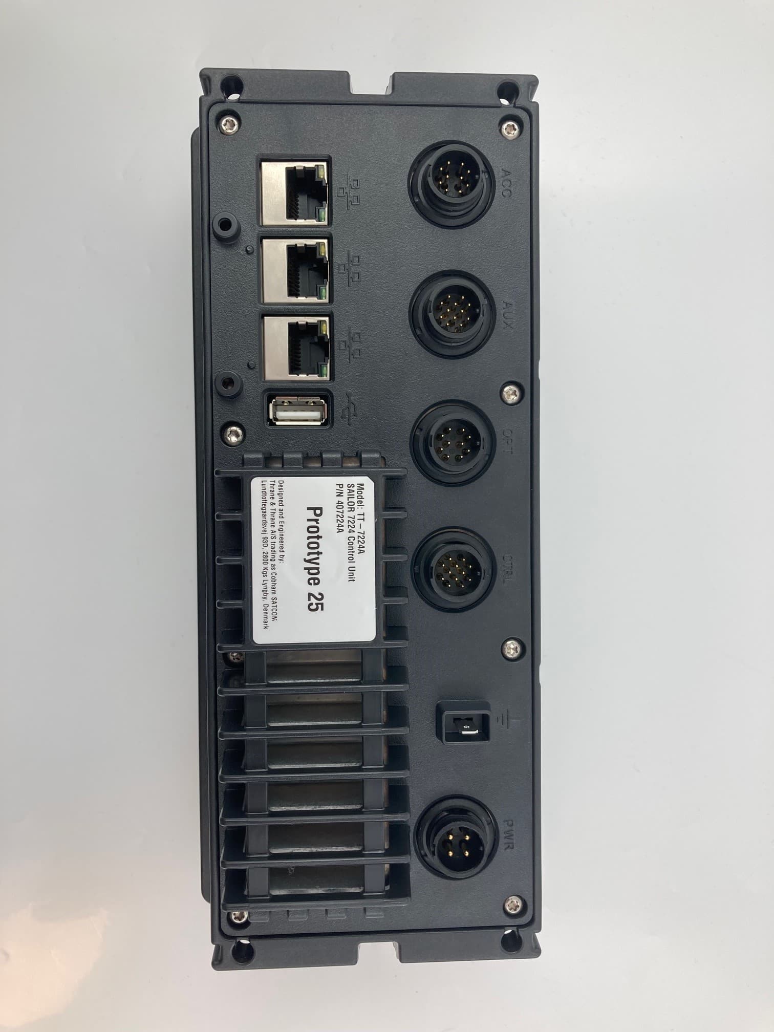
ROJ7226
Nov 24, 2022SAILOR 7222 VHF DSC Class A
Equipment Class
GVH - Part 80 VHF Transmitter (GMDSS)
ROJ-3711A
May 01, 2015Satellite Terminal
Equipment Class
DTS - Digital Transmission System
ROJEXPLORER-710
Jun 06, 2014TT-3720B Land-portable broadband terminal for Inmarsat satellite system Consists of TT-3732B Transceiver and TT-3703B Antenna
Equipment Class
TNB - Licensed Non-Broadcast Station Transmitter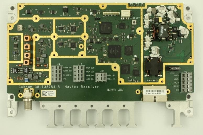
ROJ6390
Nov 20, 2013NAVTEX Receiver
Equipment Class
RNV - Part 80 NAVTEX Receiver