ROJ6300SAILOR 6311 MF/HF 150W DSC CLass A FCC
Thrane & Thrane A/S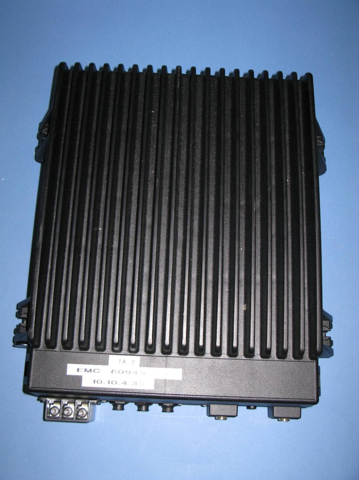
Click to zoom
Application Details
- Equipment Class
- GHF - Part 80 HF Transmitter (GMDSS)
- Date of Grant
- May 18, 2011
- Application Purpose
- Original Equipment
- Date of Application
- May 12, 2011
- Equipment Note
- SAILOR 6311 MF/HF 150W DSC CLass A FCC
- Frequency Range
- 1.60500000 - 27.50000000
- Company
- Thrane & Thrane A/S
- Country
- Denmark
Documents & Files
Document Text
Text extracted from the exhibit documents filed with the FCC. Open a document above to read the original.
Users Manual
SAILOR 6300 MF/HF DSC 150W/250W/500W USER MANUAL SAILOR 6300 MF/HF DSC 150W/250W/500W User manual Document number: 98-131070-A Release date: February 16, 2011 Disclaimer Any responsibility or liability for loss or damage in connection with the use of this product and the accompanying documentation is disclaimed by Thrane & Thrane. The information in this manual is provided for information purposes only, is subject to change without notice and may contain errors or inaccuracies. Manuals issued by Thrane & Thrane are periodically revised and updated. Anyone relying on this information should acquire the most current version e.g. from http://www.thrane.com or from the distributor. Thrane & Thrane is not responsible for the content or accuracy of any translations or reproductions, in whole or in part, of this manual from any other source. Copyright © 2011 Thrane & Thrane A/S. All rights reserved. Printed in Denmark. Trademark Acknowledgements •Thrane & Thrane is a registered trademark of Thrane & Thrane A/S in the European Union and the Unites States of America. •SAILOR is a registered trademarks of Thrane & Thrane A/S. •Other product and company names mentioned in this manual may be trademarks or trade names of their respective owners. GPL notification The software included in this product contains copyrighted software that is licensed under the GPL/LGPL. The verbatim licenses can be found online at: http://www.gnu.org/licenses/old-licenses/gpl-2.0.html http://www.gnu.org/licenses/old-licenses/lgpl-2.1.html You may obtain the complete corresponding source code from us for a period of three years after our last shipment of this product, which will be no earlier than December 31, 2015, by sending a money order or check for DKK 50 to: SW Technology/GPL Compliance, Thrane & Thrane A/S, Lundtoftegaardsvej 93D 2800 Lyngby DENMARK Please write "source for product SAILOR 6300 MF/HF DSC" in the memo line of your payment. You may also find a copy of the source at http://www.thrane.com/foss. This offer is valid to anyone in receipt of this information. Warranties Any attempt to install or execute software not supplied by Thrane & Thrane on this device will result in the warranty being void. Any attempt to modify the software on this device in a way not specified by Thrane & Thrane will result in the warranty being void. iv Safety summary1 The following general safety precautions must be observed during all phases of operation, service and repair of this equipment. Failure to comply with these precautions or with specific warnings elsewhere in this manual violates safety standards of design, manufacture and intended use of the equipment. Thrane & Thrane assumes no liability for the customer's failure to comply with these requirements. GROUND THE EQUIPMENT To minimise shock hazard, the equipment chassis and cabinet must be connected to an electrical ground and the cable instructions must be followed. DO NOT OPERATE IN AN EXPLOSIVE ATMOSPHERE Do not operate the equipment in the presence of flammable gases or fumes. Operation of any electrical equipment in such an environment constitutes a definite safety hazard. KEEP AWAY FROM LIVE CIRCUITS Operating personnel must not remove equipment covers. Component replacement and internal adjustment must be made by qualified maintenance personnel. Do not service the unit with the power cable connected. Always disconnect and discharge circuits before touching them. Service General service must be done by skilled service personnel. Caution!Electric shock hazard. Do not open the equipment. Only skilled service personnel may service and repair the equipment. v RF exposure hazards and instructions Your Thrane & Thrane radio generates electromagnetic RF (radio frequency) energy when transmitting. To ensure that you and those around you are not exposed to excessive amounts of energy and thus to avoid health hazards from excessive exposure to RF energy, all persons must obey the following: Warranty limitation The radio is not a user maintainable unit, and under no circumstances should the unit be opened except by authorized personnel. Unauthorized opening of the unit will invalidate the warranty. Caution!Never touch the Antenna Tuning Unit or feeder wire when the MF/HF radio is transmitting. High voltage which can cause death or serious injury is present at the locations shown in the illustration below. Unit Antenna Tuning MF/HF SAILOR 638x vi Emergency calls MM MM M AA AA A YY YY Y DD DD D AA AA A YY YY Y NANA NANA NA MEME MEME ME of the VV VV V EE EE E SS SS S SS SS S ELEL ELEL EL in distress CC CC C ALAL ALAL AL LL LL L SS SS S IGNIGN IGNIGN IGN or other IDENIDEN IDENIDEN IDEN TT TT T IFICIFIC IFICIFIC IFIC AA AA A TT TT T IONION IONION ION MM MM M MM MM M S S SS S II II I (If the initial alert is sent by DSC) PP PP P OO OO O SS SS S ITIT ITIT IT IONION IONION ION given as ll ll l atat atat at itit itit it udeude udeude ude and longitlongit longitlongit longit udeude udeude ude or If latitude and longitude are not known or if time is insufficient, in relation to a known geographical location NANA NANA NA TURETURE TURETURE TURE of distress Kind of AA AA A SS SS S SS SS S II II I SS SS S TT TT T ANCANC ANCANC ANC EE EE E required Any other useful INFINF INFINF INF OROR OROR OR MM MM M AA AA A TT TT T IONION IONION ION MM MM M AA AA A YY YY Y DD DD D AA AA A YY YY Y -M-M -M-M -M AA AA A YY YY Y DD DD D AA AA A YY YY Y -M-M -M-M -M AA AA A YY YY Y DD DD D AA AA A YY YY Y This is NANA NANA NA ME-NAME-NA ME-NAME-NA ME-NA ME-NAME-NA ME-NAME-NA ME-NA MEME MEME ME CC CC C ALAL ALAL AL LL LL L SS SS S IGNIGN IGNIGN IGN or other IDENTIFICATION MM MM M MM MM M SS SS S II II I (If the initial alert is sent by DSC) Use the HANDHAND HANDHAND HAND SS SS S ETET ETET ET for voice calling LL LL L ifif ifif if t Ct C t Ct C t C ovov ovov ov erer erer er PP PP P rr rr r ee ee e ss ss s s RED Buttons RED Button s RED Buttons RED Button s RED Button until beep sounds continuously (more than 3…
Text truncated - open the document above for the full version.
Users Manual
Correction sheet 98-133352-A1/4 1111 Correction sheet Correction sheet1 SAILOR 6300 MF/HF DSC 150W/250W/500W User manual Please note insufficiencies on the pages 3, 10 and 27 in the SAILOR 6300 MF/HF DSC user manual (98-131070-A). These have been corrected in this document. •Corrections on page 3: Controls on the front, bulleted item 9 edited •Corrections on page 10: Adjusting RF gain, 3rd paragraph edited, 4th paragraph removed •Corrections on page 27: Display for a session, a note has been added Correction sheet 2/498-133352-A Page 3 in the SAILOR 6300 MF/HF DSC user manual: Controls on the front 1. Loudspeaker. 2. Four soft keys with function title in the display. 3. Large TFT color display. 4. Alphanumerical keys to enter Rx or Tx frequency or text strings. 5.CH button for channel selection. 6.Rx/Tx Key to enter Tx or RX frequency. 7. Connector for handset or handmicrophone. 8.Distress button for sending a Distress alert. 9.RF gain control (IF). 10. Volume knob with key-press function for power on/off. 11. Selector knob with key-press function for radio operation and setup. 12.Mode key to select the work mode: SSB, AM Broadcast, DSC, Telex. 13. Replay button to play back up to 240 s voice message. 12346 78910111213 5 Correction sheet 98-133352-A3/4 1111 Correction sheet Page 10 in the SAILOR 6300 MF/HF DSC user manual: Adjusting RF gain Use RF gain to control audibility of the incoming signal. Turn the RF gain control knob fully: •clockwise: maximum RF gain — maximum sensitivity •anti-clockwise: minimum RF gain — minimum sensitivity The larger the signal strength bar, the larger the signal must be in order to be audible. After entry of a new receive frequency the RF gain is set to maximum. The function is enabled in SSB telephony and disabled in all other modes. kHz/ RX kHz/ RX Correction sheet 4/498-133352-A Page 27 in the SAILOR 6300 MF/HF DSC user manual: Display for a session In the lower part of the display the type of session, the current state, MMSI number of the other party and lapsed time since the reception of a call request or an acknowledgment is shown. The session state icons, in the example V and R, show the state of the session: •ACTIVE — the session icon is inverted, the transmitter tuned into the communication channel (in the example , a DSC Routine call). •HOLD — normal view, parked session (in the example, MF/HF voice communication. •FLASHING — Call has updates that need handling or viewing For more information on the session state icons see Session state icons D, U, S, R, V and T below. Note If two identical polling or test calls are sent from the same MMSI and the operator wants to resend a confirmation to the second call received, it is necessary to put the session on hold and then activate it again. QUIT HOLD VIEW MORE COMM WITH 123456789 GROUP RX 0:12 RV 4357.0 4065.0 SSB 401 kHz/TX RX kHz/ Session state icons Session line Session status R V
Users Manual
EMERGENCY CALL SAILOR VHF and MF/HF MM MM M AA AA A YY YY Y DD DD D AA AA A YY YY Y NANA NANA NA MEME MEME ME of the VV VV V EE EE E SS SS S SS SS S ELEL ELEL EL in distress CC CC C ALAL ALAL AL LL LL L SS SS S IGNIGN IGNIGN IGN or other IDENIDEN IDENIDEN IDEN TT TT T IFICIFIC IFICIFIC IFIC AA AA A TT TT T IONION IONION ION MM MM M MM MM M S S SS S II II I (If the initial alert is sent by DSC) PP PP P OO OO O SS SS S ITIT ITIT IT IONION IONION ION given as ll ll l atat atat at itit itit it udeude udeude ude and longitlongit longitlongit longit udeude udeude ude or If latitude and longitude are not known or if time is insufficient, in relation to a known geographical location NANA NANA NA TURETURE TURETURE TURE of distress Kind of AA AA A SS SS S SS SS S II II I SS SS S TT TT T ANCANC ANCANC ANC EE EE E required Any other useful INFINF INFINF INF OROR OROR OR MM MM M AA AA A TT TT T IONION IONION ION MM MM M AA AA A YY YY Y DD DD D AA AA A YY YY Y -M-M -M-M -M AA AA A YY YY Y DD DD D AA AA A YY YY Y -M-M -M-M -M AA AA A YY YY Y DD DD D AA AA A YY YY Y This is NANA NANA NA ME-NAME-NA ME-NAME-NA ME-NA ME-NAME-NA ME-NAME-NA ME-NA MEME MEME ME CC CC C ALAL ALAL AL LL LL L SS SS S IGNIGN IGNIGN IGN or other IDENTIFICATION MM MM M MM MM M SS SS S II II I (If the initial alert is sent by DSC) Use the HANDHAND HANDHAND HAND SS SS S ETET ETET ET for voice calling LL LL L ifif ifif if t Ct C t Ct C t C ovov ovov ov erer erer er PP PP P rr rr r ee ee e ss ss s s RED Buttons RED Button s RED Buttons RED Button s RED Button until beep sounds continuously (more than 3 seconds) SHIP‘s NAME: CALLSIGN: MMSI: OWN OWN OWN OWN OWN IDID IDID ID 99-132140 Press VHF MF HF4 HF6 HF8 HF12 HF16 Channel 70 2187.5 kHz 4207.5 kHz 6312.0 kHz 8414.5 kHz 12577.0 kHz 16804.5 kHz Channel 16 2182.0 kHz 4125.0 kHz 6215.0 kHz 8291.0 kHz 12290.0 kHz 16420.0 kHz - - - - - 2174.5 kHz 4177.5 kHz 6268.0 kHz 8376.5 kHz 12520.0 kHz 16695.0 kHz DD DD D SCSC SCSC SC RR RR R adiadi adiadi adi otot otot ot elephonelephon elephonelephon elephon yy yy y NBDPNBDP NBDPNBDP NBDP DIDI DIDI DI SS SS S TRETRE TRETRE TRE SS SS S SS SS S and C and C and C and C and C OMOM OMOM OM MM MM M UNICUNIC UNICUNIC UNIC AA AA A TT TT T IONION IONION ION FREQUENCIEFREQUENCIE FREQUENCIEFREQUENCIE FREQUENCIE SS SS S _ _ _ _ _ _ _ _ _ _ _ _ _ _ _ _ _ _ _ _ _ _ _ _ _ _ _ _ _ _ _ _ _ _ _ _ Remember to use the correct HF-procedures Don‘t forget your EPIRB is the secondary means of alerting _ _ _ _ _ _ _ _ _ _ _ _ _ _ _ _ _ _ _ _ _ _ _ _ _ _ _ _ _ _ _ _ _ _ _ _ 98-132369-A
Users Manual
SAILOR 6300 MF/HF Radiotelex USER MANUAL SAILOR 6300 MF/HF Radiotelex User manual Document number: 98-132519-A Release date: January 18, 2011 Disclaimer Any responsibility or liability for loss or damage in connection with the use of this product and the accompanying documentation is disclaimed by Thrane & Thrane. The information in this manual is provided for information purposes only, is subject to change without notice and may contain errors or inaccuracies. Manuals issued by Thrane & Thrane are periodically revised and updated. Anyone relying on this information should acquire the most current version e.g. from http://www.thrane.com or from the distributor. Thrane & Thrane is not responsible for the content or accuracy of any translations or reproductions, in whole or in part, of this manual from any other source. Copyright © 2011 Thrane & Thrane A/S. All rights reserved. GPL notification The software included in this product contains copyrighted software that is licensed under the GPL/LGPL. The verbatim licenses can be found online at: http://www.gnu.org/licenses/old-licenses/gpl-2.0.html http://www.gnu.org/licenses/old-licenses/lgpl-2.1.html You may obtain the complete corresponding source code from us for a period of three years after our last shipment of this product, which will be no earlier than December 31, 2015, by sending a money order or check for DKK 50 to: SW Technology/GPL Compliance, Thrane & Thrane A/S, Lundtoftegaardsvej 93D 2800 Lyngby DENMARK Please write "source for product SAILOR 6300 MF/HF Radiotelex" in the memo line of your payment. You may also find a copy of the source at http://www.thrane.com/foss. This offer is valid to anyone in receipt of this information. Warranties Any attempt to install or execute software not supplied by Thrane & Thrane on this device will result in the warranty being void. Any attempt to modify the software on this device in a way not specified by Thrane & Thrane will result in the warranty being void. Trademark Acknowledgements •Thrane & Thrane is a registered trademark of Thrane & Thrane A/S in the European Union and the United States. •SAILOR is a registered trademark of Thrane & Thrane A/S in the European Union, the United States and other countries. •Other product and company names mentioned in this manual may be trademarks or trade names of their respective owners. iv Safety summary1 The following general safety precautions must be observed during all phases of operation, service and repair of this equipment. Failure to comply with these precautions or with specific warnings elsewhere in this manual violates safety standards of design, manufacture and intended use of the equipment. Thrane & Thrane assumes no liability for the customer's failure to comply with these requirements. GROUND THE EQUIPMENT To minimise shock hazard, the equipment chassis and cabinet must be connected to an electrical ground and the cable instructions must be followed. DO NOT OPERATE IN AN EXPLOSIVE ATMOSPHERE Do not operate the equipment in the presence of flammable gases or fumes. Operation of any electrical equipment in such an environment constitutes a definite safety hazard. KEEP AWAY FROM LIVE CIRCUITS Operating personnel must not remove equipment covers. Component replacement and internal adjustment must be made by qualified maintenance personnel. DO NOT SUBSTITUTE PARTS OR MODIFY EQUIPMENT Because of the danger of introducing additional hazards, do not substitute parts or perform any unauthorized modification to the equipment. COMPASS SAFE DISTANCE Minimum compass safe distance: 1.3 m from the Message Terminal. Failure to comply with the rules above will void the warranty! v About the manual2 Manual overview This manual describes how to use the SAILOR 6300 MF/HF Radiotelex. Note that this manual does not cover installation of the system. For information on installation refer to the installation manuals [2] and [3] listed below. This manual has the following chapters: •Introduction contains an overview of the Radiotelex system. •Using the system explains how to send Distress alerts and how to use the Radiotelex application for sending and receiving telex messages. •Tro u b le s h o ot i n g contains a short troubleshooting guide and explains how to check the status of the system. Related documents The below list shows the documents related to this manual and to the Radiotelex system. RefTitle and description Document number [1]SAILOR 6300 MF/HF DSC, User manual 98-131070 [2]SAILOR 6300 MF/HF DSC, Installation manual 98-130890 [3]SAILOR 6006 and SAILOR 6007 Message Terminal, Installation manual 98-130088 [4]SAILOR 6081 PSU and Charger, Installation and user manual 98-130980 vi Typography In this manual, typography is used as indicated below: Bold is used for the following purposes: •To emphasize words or sentences. Example: “Do not push the Distress button if you are not in distress”. •To indicate what the user should select in the user interface. Example: “Select Message > Inbox”. Italic is used to emphasize the paragraph title in cross-references. Example: “For further information, see System overview on page 2”. vii Contents Chapter 1Introduction System overview .................................................................2 The Radiotelex application .................................................3 Chapter 2Using the system Before you start ..................................................................6 Sending a DSC Distress alert .............................................. 7 Sending a Distress telex .....................................................8 Cancelling a Distress alert ..................................................9 Overview of the Radiotelex user interface ......................... 10 Setting up a telex call ........................................................13 Making a telex call ............................................................16 Messages .........................................................…
Text truncated - open the document above for the full version.
Users Manual
INSTALLATION AND USER MANUAL SAILOR 6101 and SAILOR 6103 Alarm Panel SAILOR 6101 and SAILOR 6103 Alarm Panel Installation and user manual Document number: 98-130981-DraftA7 Release date: July 5, 2010 Disclaimer Any responsibility or liability for loss or damage in connection with the use of this product and the accompanying documentation is disclaimed by Thrane & Thrane. The information in this manual is provided for information purposes only, is subject to change without notice and may contain errors or inaccuracies. Manuals issued by Thrane & Thrane are periodically revised and updated. Anyone relying on this information should acquire the most current version e.g. from http://www.thrane.com or from the distributor. Thrane & Thrane is not responsible for the content or accuracy of any translations or reproductions, in whole or in part, of this manual from any other source. Copyright © 2010 Thrane & Thrane A/S. All rights reserved. Trademark Acknowledgements •Thrane & Thrane is a registered trademark of Thrane & Thrane A/S in the European Union and the United States. •Inmarsat is a registered trademark of the International Maritime Satellite Organisation (IMSO) and is licensed by IMSO to Inmarsat Limited and Inmarsat Ventures plc. •SAILOR is a registered trademark of Thrane & Thrane A/S in the European Union, the United States and other countries. •Other product and company names mentioned in this manual may be trademarks or trade names of their respective owners. iii Safety summary1 The following general safety precautions must be observed during all phases of operation, service and repair of this equipment. Failure to comply with these precautions or with specific warnings elsewhere in this manual violates safety standards of design, manufacture and intended use of the equipment. Thrane & Thrane assumes no liability for the customer's failure to comply with these requirements. DO NOT OPERATE IN AN EXPLOSIVE ATMOSPHERE Do not operate the equipment in the presence of flammable gases or fumes. Operation of any electrical equipment in such an environment constitutes a definite safety hazard. KEEP AWAY FROM LIVE CIRCUITS Operating personnel must not remove equipment covers. Component replacement and internal adjustment must be made by qualified maintenance personnel. Do not service the unit with the power cable connected. Always disconnect and discharge circuits before touching them. DO NOT SUBSTITUTE PARTS OR MODIFY EQUIPMENT Because of the danger of introducing additional hazards, do not substitute parts or perform any unauthorized modification to the equipment. COMPASS SAFE DISTANCE Minimum compass safe distance: 1 m. Failure to comply with the rules above will void the warranty! iv About the manual2 Intended readers This manual is an installation and user manual for the two types of Alarm Panel, SAILOR 6101A and SAILOR 6103A. The manual is intended primarily for installers of the system and service personnel. Personnel installing or servicing the system must be properly trained and authorized by Thrane & Thrane. It is important that you observe all safety requirements listed in the beginning of this manual, and install the system according to the guidelines in this manual. Manual overview This manual has the following chapters: •Introduction - a short description of the two types of Alarm Panel. •Using the Alarm Panel - a short guide on how to use the Alarm Panel to send distress alerts, receive distress or urgency messages, set up light and sound and test the Alarm Panel. •Installing the Alarm Panel - a description of how to unpack, store and install the Alarm Panel. •Connecting cables - descriptions and pin-out for the connectors, guidelines for connecting the Alarm Panel and descriptions of the buttons. •Service and repair - a short description of how to handle defective units. •Specifications - technical specifications for the Alarm Panel. v Table of Contents Chapter 1Introduction The Alarm Panel ................................................................. 1 Chapter 2Using the Alarm Panel Starting up the Alarm Panel ...............................................6 Sending a Distress alert ..................................................... 7 Receiving Distress or Urgency messages ............................8 Displaying faults ................................................................9 General functions ............................................................. 10 Chapter 1Installing the Alarm Panel Initial inspection ...............................................................14 Storage .............................................................................14 To install the Alarm Panel .................................................15 Chapter 2Connecting cables Connectors ....................................................................... 22 Cable requirements .......................................................... 26 Connecting the Alarm Panel ............................................. 27 Connecting multiple Alarm Panels ...................................28 Chapter 3Service and repair Introduction ..................................................................... 29 Repacking for shipment ...................................................30 Table of Contents vi App. ASpecifications General specifications ...................................................... 31 Glossary.........................................................................................33 Index.........................................................................................35 1 Chapter 1 1111 Introduction Introduction1 The Alarm Panel The Alarm Panel is used for sending distress alerts and showing visible and audible indication of incoming distress messages. Normally the Alarm Panel is installed at the conning position on the bridge. The distress buttons are protected by spring loaded covers to avoid unintended activation of a distress alert. The distress butt…
Text truncated - open the document above for the full version.
Attestation Statements
C e r t i f i c a t e of EC Type-examination (Module B) Certificate No.: 10212004/AA/00 Product Category: A.1/5.14 A.1/5.15 With respect to Marine Equipment Directive 96/98/EC and the amending Directive 2009/26/EC, Telefication declares that the equipment: Product description: 150W GMDSS MF/HF SSB Radiotelephone with integrated Class-A DSC-controller, NBDP terminal and DSC-watchkeeping receiver Trademark: See annex 3 Family name: System 6000 MF/HF Type designation: See annex 3 Serial No: See annex 3 Hard-|Software release No: BOM Revision A|SW: 1.xx Manufacturer: Thrane & Thrane A/S Address: Lundtoftegaardsvej 93D City: 2800 Lyngby Country: Denmark complies with the international instruments and test standards as listed in the Annex. This certificate is granted to: Name: Thrane & Thrane A/S Address: Lundtoftegaardsvej 93D City: 2800 Lyngby Country: Denmark Validity of this certificate is 5 years; Expiry date: 16 May 2016 This certificate has THREE Annexes. Zevenaar, 16 May 2011 W.J.M. Jong Operations Manager Certification General conditions Remarks and observations The following conditions are applicable: Annex 1 to EC type-examination16 May 2011 Number: 10212004/AA/00Annex 1, Page 1 of 1 •Each product to which this certificate relates shall be provided with Marine markings. The Marine marking consist of symbol in the form of a wheel followed by the identification number of the responsible Notified Body for module D, E, F or G, and by the last two digits of the number of the year in which the mark is affixed. •The holder of this Certificate has drawn up a Declaration of conformity to type with Directive 96/98/EC and amending Directives, declaring that the product(s) described in this EC Type- examination certificate, satisfy the requirements that apply to them. •Each product shall be identified by means of type, batch and/or serial numbers and the name of the manufacturer and/or importer. •If the equipment is to be modified, Telefication shall be notified immediately. Depending on the modifications, Telefication may have additional examinations carried out in consultation with the applicant. •Enforcement of a new amending directive voids the validity of this certificate for (re)placement of the product onboard ships. This certificate covers the following 150 Watt System 6000 versions: - 150W MF/HF SSB radiotelephone with integrated class-A DSC controller and 2187.5 kHz watchkeeping receiver. - 150W MF/HF SSB radiotelephone with integrated class-A DSC controller and 6-ch scanning watchkeeping receiver. - 150W MF/HF SSB radiotelephone with integrated class-A DSC controller, NBDP controller and 6-channel scanning watchkeeping receiver. There are two transceiver-unit versions; only difference is the type of RF power-amplifier, BJT or FET. All systems utilize the same hardware; version difference is by software programming. For NBDP-operation however, the following hardware must be added: keyboard TT-6001A, printer TT-1252B/TT- 3608A and message terminal TT-6006A. Verification of which system is on-board ships, is done by readout of the special menu-item on the control-unit: The Config Status clearly indicates what functionality is active and as such the system version is defined. Final software version which has been seen during testing: 1.04. The products to which this certificate relates include the following units or equipment: - TT-6301A: Control-unit - TT-6201A: Handset - TT-6202A: Hand microphone - TT-6203A: Handset (waterproof) - TT-6360A: Transceiver-unit (150W BJT PA) - TT-6361A: Transceiver-unit (150W FET PA) - TT-6381A: Antenna Tuning Unit - TT-6081A: AC power supply with charger - TT-6080A: AC power supply - PS4655: AC power supply - TT-1252B or TT-3608A: Printer - TT-6001A: Keyboard - TT-6006A: Message Terminal - TT-6103A: Distress Alarm Panel - TT-6209A: Accessory Connection Box - TT-6208A: CU Connection Box - TT-6197A: Ethernet Switch - TT-6270A: External Speaker Telefication, Edisonstraat 12A, 6902 PK Zevenaar, The Netherlands Tel: +31 316 583 180, Fax: +31 316 583 189 Annex 2 to EC type-examination16 May 2011 Number: 10212004/AA/00Annex 2, Page 1 of 2 Documentation lodged for this EC type-examination Test Reports: Product Documentation: International instruments and test standards The equipment complies with: -----Delta: DANAK-1911259, 07 February 2011 -----Delta: DANAK-195321, 12 July 2000 -----Delta: DANAK-198724, 13 April 2007 -----Nemko A/S: 130708, 14 September 2009 -----Nemko A/S: 138930-3, 23 November 2010 -----Nemko A/S: E10178.00, 17 February 2011 -----RES Laboratory Ltd.: N 01.11, 04 February 2011 -----RES Laboratory Ltd.: N 02.11, 04 February 2011 -----SGS Taiwan Ltd.: HC70206/2010, 15 September 2010 -----Telefication B.V.: 20103937200, 02 May 2011 -----Telefication B.V.: 20103937300, 05 May 2011 -----Telefication B.V.: 20103937302, 02 May 2011 -----Telefication B.V.: 20103937303, 05 May 2011 -----Telefication B.V.: 20103937304, 05 May 2011 -----Telefication B.V.: 20103937307, 29 April 2011 -----Telefication B.V.: 20103937308, 29 April 2011 -----Telefication B.V.: 20103937309, 05 May 2011 -----Telefication B.V.: 98735330, 17 December 2001 -----Telefication B.V.: 99816920, 22 August 2007 -----Telefication B.V.: 99816933, 22 August 2007 -----Telefication B.V.: 99817230, 22 August 2007 -----Telefication B.V.: 99817231, 22 August 2007 -----Telefication B.V.: 99817232-rev 1.0, 04 October 2007 -----Telefication B.V.: 99817530-rev 1.0, 06 February 2008 -----Telefication B.V.: 99817531, 07 January 2008 -----Telefication B.V.: 99817533-rev 1.0, 06 February 2008 -----Assembly drawings -----Bill of materials -----Electric diagrams -----Photos -----User manual -----Installation manual -----EN 300 338-1February 2010V1.3.1. -----EN 300 338-2February 2010V1.3.1 -----EN 300 373-1January 2011V1.3.1 -----EN 301 033September 2010V1.3.1 -----EN 60945October 2002Edition 4 -----ETS 300 067November 1990 -----ETS 300 067/A1October 1993 -----IEC 61162-1November 2010Ed. 4.0 -----IMO Resolu…
Text truncated - open the document above for the full version.
Cover Letter(s)
FCC, Request for non-disclosure Date: 10-Aug-09 RF_501, Issue 5 Page 1 of 1 Company Name: Thrane & Thrane A/S Address: Lundtoftegårdsvej 93 D City: Kgs. Lyngby Country: Denmark To: Telefication B.V., Dept. FCC TCB Edisonstraat 12A 6902 PK ZEVENAAR The Netherlands Subject: Request for confidentiality FCC ID: ROJ6300 Reference number: ###### Dear FCC TCB, 1. Long-Term Confidentiality Pursuant to 47 CFR Section 0.459(a) & (b), we hereby requests non-disclosure and confidential treatment of the following materials submitted in support o…
Text truncated - open the document above for the full version.
Contact Information
Applicant
Niels Peter Agdal(Mr.)
Technical Contact
Non-Technical Contact
Thrane & Thrane A/SJesper Holst
[email protected]+45 39558800
Test Firm
Kiwa Nederland B.V.Willem Jong
[email protected]+31 889983621
Technical Specifications
| # | Rule Parts | Frequency Range | Power Output | Emission | Tolerance |
|---|---|---|---|---|---|
| 2 | 80.1101(c)(4) | 1.605 MHz - 27.5 MHz | 120 W | 300HJ2B | 10 Hz |
Other Applications from Thrane & Thrane A/S

ROJ-8033A
Aug 22, 2024Satellite IP router
Equipment Class
DTS - Digital Transmission System
ROJ7226
Nov 24, 2022SAILOR 7222 VHF DSC Class A
Equipment Class
GVH - Part 80 VHF Transmitter (GMDSS)
ROJ-3723A
Mar 24, 2020Inmarsat landmobile terminal
Equipment Class
TNB - Licensed Non-Broadcast Station Transmitter
ROJ-3711A
May 01, 2015Satellite Terminal
Equipment Class
DTS - Digital Transmission System
ROJEXPLORER-710
Jun 06, 2014TT-3720B Land-portable broadband terminal for Inmarsat satellite system Consists of TT-3732B Transceiver and TT-3703B Antenna
Equipment Class
TNB - Licensed Non-Broadcast Station Transmitter