ROJEXPLORER325EXPLORER 325 landmobile broadband terminal for Inmarsat satellite system
Thrane & Thrane A/S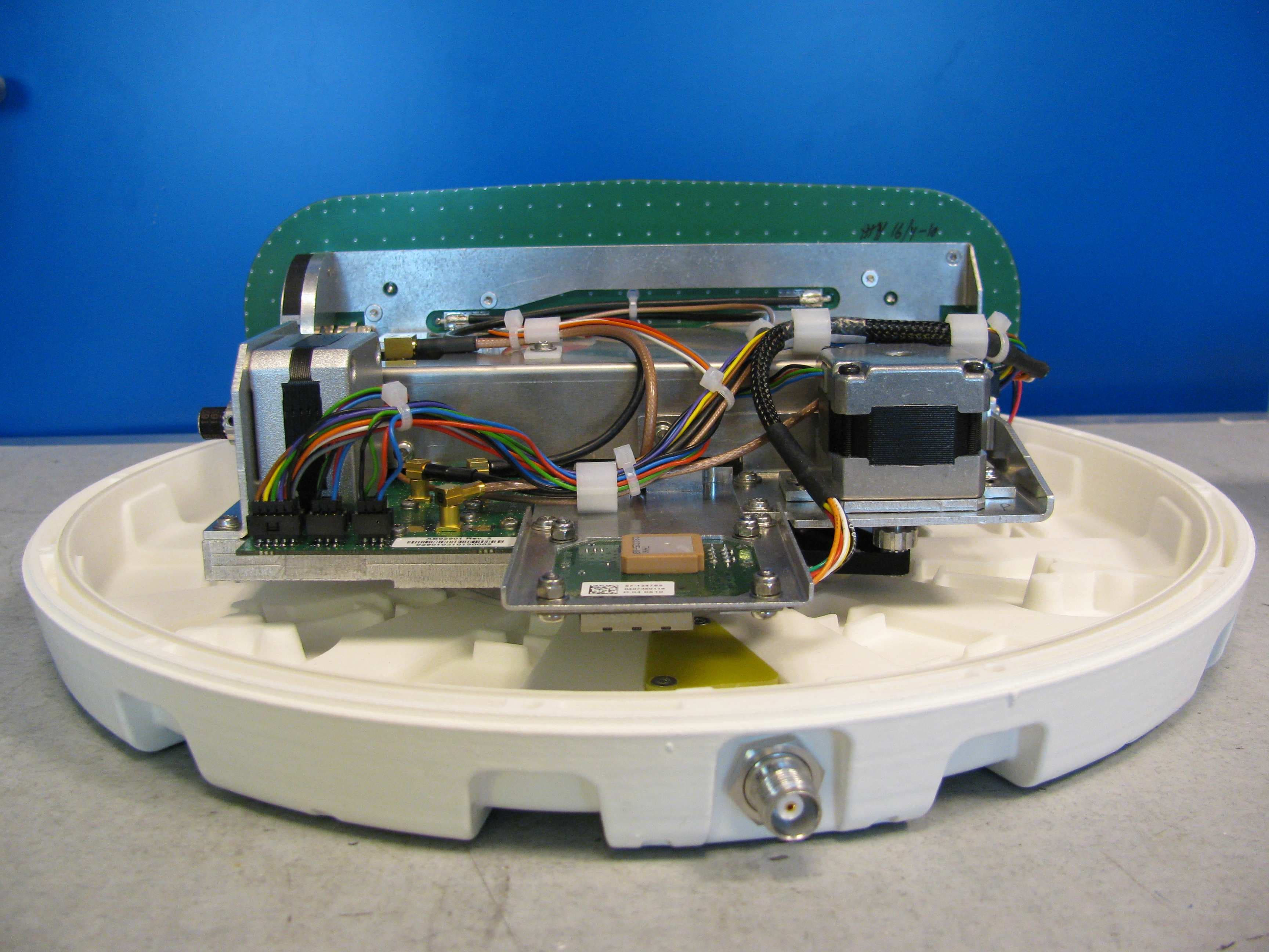
Click to zoom
Application Details
- Equipment Class
- TNB - Licensed Non-Broadcast Station Transmitter
- Date of Grant
- Oct 14, 2010
- Application Purpose
- Original Equipment
- Date of Application
- Oct 14, 2010
- Equipment Note
- EXPLORER 325 landmobile broadband terminal for Inmarsat satellite system
- Frequency Range
- 1626.50000000 - 1660.50000000
- Company
- Thrane & Thrane A/S
- Country
- Denmark
Documents & Files
Document Text
Text extracted from the exhibit documents filed with the FCC. Open a document above to read the original.
Users Manual
USER MANUAL EXPLORER ® 325 98-131305-Aii EXPLORER ® 325 Document number: 98-131305-A Release date: June 17, 2010 Disclaimer Any responsibility or liability for loss or damage in connection with the use of this product and the accompanying documentation is disclaimed by Thrane & Thrane. The information in this manual is provided for information purposes only, is subject to change without notice and may contain errors or inaccuracies. Manuals issued by Thrane & Thrane are periodically revised and updated. Anyone relying on this information should acquire the most current version e.g. from http://www.thrane.com or from the distributor. Thrane & Thrane is not responsible for the content or accuracy of any translations or reproductions, in whole or in part, of this manual from any other source. Copyright © 2010 Thrane & Thrane A/S. All rights reserved. Trademark acknowledgements: •Thrane & Thrane is a registered trademark of Thrane & Thrane A/S in the European Union and the United States. •EXPLORER is a registered trademark of Thrane & Thrane A/S in the European Union and the United States. •Windows and Outlook are registered trademarks of Microsoft Corporation in the United States and other countries. •Inmarsat is a registered trademark of International Maritime Satellite Organisation (IMSO) and is licensed by IMSO to Inmarsat Limited and Inmarsat Ventures plc. •Inmarsat’s product names are trademarks or registered trademarks of Inmarsat. •Other product and company names mentioned in this manual may be trademarks or trade names of their respective owners. Company web site www.thrane.com 98-131305-Aiii Safety summary1 The following general safety precautions must be observed during all phases of operation, service and repair of this equipment. Failure to comply with these precautions or with specific warnings elsewhere in this manual violates safety standards of design, manufacture and intended use of the equipment. Thrane & Thrane assumes no liability for the customer's failure to comply with these requirements. Observe marked areas Under extreme heat conditions do not touch areas of the terminal or antenna that are marked with this symbol, as it may result in injury. Microwave radiation hazards During transmission the antenna in this system radiates Microwave Power.This radiation may be hazardous to humans close to the antenna. When the system is powered, make sure that nobody gets closer than the recommended minimum safety distance. The minimum safety distance is 0.6 m to the side and above the antenna when the EXPLORER 325 is powered. The safety distance of 0.6 m does not apply directly below the antenna, as the radiation forms a hemisphere above the antenna. Service User access to the interior of the system units is prohibited. Only a technician authorized by Thrane & Thrane may perform service - failure to comply with this rule will void the warranty. Do not service or adjust alone Do not attempt internal service or adjustments unless another person, capable of rendering first aid resuscitation, is present. Power supply The voltage range is 10.5 - 32 V DC; 11.5 A - 4 A. Be aware of high start-up peak current: 20 A@24 V, 5ms. Do not operate in an explosive atmosphere Do not operate the equipment in the presence of flammable gases or fumes. Operation of any electrical equipment in such an environment constitutes a definite safety hazard. Keep away from live circuits Operating personnel must not remove equipment covers. Component replacement and internal adjustment must be made by qualified maintenance personnel. Do not replace components with the power cable connected. Under certain conditions, dangerous voltages may exist even with the power cable removed. To avoid injuries, always disconnect power and discharge circuits before touching them. Install and use the antenna with care Thrane & Thrane assumes no liability for any damage caused by the antenna falling off the vehicle or stressing the mounting base. It is the responsibility of the customer to ensure a safe and correct installation of the antenna. The instructions in the Installation manual are only guidelines. Failure to comply with the rules above will void the warranty! 98-131305-Aiv About the manual2 Intended readers This manual is a user manual for the EXPLORER 325 system. The manual is intended for anyone who is using or intends to use this system. No specific skills are required to operate the EXPLORER 325 system. However, it is important that you observe all safety requirements listed in the beginning of this manual, and operate the system according to the guidelines in this manual. Most current version This manual may not always reflect the latest software functionality of your EXPLORER 325 system. To obtain the latest version of the manual, please enter the Thrane & Thrane web site www.thrane.com and download the latest version from Service > Self Service Center > Downloads, or acquire it from your distributor. Manual overview Note that this manual does not cover installation nor does it cover how to use the IP handset that comes with the system. For information on installation refer to the installation manual and for information on the IP handset refer to the user manual for the IP handset. Part numbers for both manuals are listed in the next section. This manual has the following chapters: •Introduction contains a brief description of the system and an overview of the BGAN services. •Getting started explains how to insert SIM (Subscriber Identity Module) card and start up the unit. It also contains a short guide to making the first call. •Operating the system explains how to use the system. •Using the web interface explains how to use the built-in web interface of the terminal for configuration and daily use, and describes the available menus and settings, including advanced setup of interfaces. •Tro u b lesh o ot i n g contains a short troubleshooting guide and explains how to update software. It also describes the fu…
Text truncated - open the document above for the full version.
Cover Letter(s)
Thrane & Thrane A/S · Lundtoftegaardsvej 93 D · DK-2800 Kgs. Lyngby · Denmark T +45 39 55 88 00 · F +45 39 55 88 88 · [email protected] · www.thrane.com Bank: Danske Bank · Comp.reg.: 65 72 46 18 · VAT: DK-20 64 64 46 Date: Sep 07, 2010 Federal Communications Commission, EQUIPMENT APPROVAL SERVICES, P.O. Box 358315 Pittsburgh, Pa 15251-5315 ATTN: Authorization & Evaluation Division PER: 47 CFR 0.457 and 0.459 RE: FCC ID: ROJEXPLORER325 Model TT-3721A Pursuant to Sections 0.457 (d)(l)(ii) and 0.459 of the Commission’s Rules, the Applicant hereby requests confidential treatment of all of the information accompanying this Application as listed below, i.e. 1) Block Diagrams 2) Clock Block Diagrams 3) Schematic Diagrams 4) Description of Circuitry 5) Part lists 6) Tune up Manual and procedures These materials contain trade secrets and proprietary information not customarily released to public and the public disclosure of these matters might be harmful to the Applicant and provide unjustified benefit to its competitors. The Applicant understands that pursuant to Rule 0.457 (d)(l)(ii) disclosure of this Application and all accompanying documentation will not be made before the date of the Grant for this Application. Sincerely, Thrane & Thrane A/S Morten Becker Saul Research & Development
Cover Letter(s)
Thrane & Thrane A/S · Lundtoftegaardsvej 93 D · DK-2800 Kgs. Lyngby · Denmark T +45 39 55 88 00 · F +45 39 55 88 88 · [email protected] · www.thrane.com Bank: Danske Bank · Comp.reg.: 65 72 46 18 · VAT: DK-20 64 64 46 Date: May 17. 2010 Federal Communications Commission, EQUIPMENT APPROVAL SERVICES, P.O. Box 358315 Pittsburgh, Pa 15251-5315 ATTN: Authorization & Evaluation Division RE: FCC ID ROJEXPLORER325 Model TT-3721A Gentlemen: This Letter will authorize the appointment of Nemko. to act as our Agent in all FCC matters. This appointment is affective until otherwise notified by us. This is to advise that we are in full compliance with the Anti-Drug Abuse Act. The Applicant is not subject to a denial of federal benefits pursuant to Section 5301 of the Anti-Drug Abuse Act of 1998,21 USC 862, and no party to the application is subject to a denial of federal benefits pursuant to that section. Sincerely, Thrane & Thrane A/S Morten Becker Saul RF Senior Engineer BGAN Research & Development
Cover Letter(s)
Thrane & Thrane A/S · Lundtoftegaardsvej 93 D · DK-2800 Kgs. Lyngby · Denmark T +45 39 55 88 00 · F +45 39 55 88 88 · [email protected] · www.thrane.com Bank: Danske Bank · Comp.reg.: 65 72 46 18 · VAT: DK-20 64 64 46 Date: Oct 12, 2010 Re.: Equipment Type No and Brand. To Whom It May Concern: The EXPLORER 325 System includes the following main units: TT-3721A EXPLORER 325 System PN = 403721A Consisting of: TT-3733A EXPLORER 325 Terminal PN = 403733A TT-3058A EXPLORER 325 Antenna PN = 403058A Sincerely, Thrane & Thrane A/S Morten Becker Saul RF engineer BGAN Research & Development
ID Label/Location Info
Thrane & Thrane A/S · Lundtoftegaardsvej 93 D · DK-2800 Kgs. Lyngby · Denmark T +45 39 55 88 00 · F +45 39 55 88 88 · [email protected] · www.thrane.com Bank: Danske Bank · Comp.reg.: 65 72 46 18 · VAT: DK-20 64 64 46 Date: Sep 30, 2010 Re.: Equipment Type No and Brand. To Whom It May Concern: The EXPLORER 325 System includes the following main units: TT-3721A EXPLORER 325 System PN = 403721A Consisting of: TT-3733A EXPLORER Terminal PN = 403733A TT-3058A EXPLORER 325 Antenna PN = 403058A Sincerely, Thrane & Thrane A/S Morten Becker Saul RF engineer BGAN Research & Development
Internal Photos
TT3058A Part locations: GPS Module Top view GPS Module Bottom view HPA / LNA Board Top view HPA / LNA Board Bottom view
Internal Photos
Figur 1 PSM board Figur 2 PSM Board Figur 3 MainBoard Figur 4 MainBoard
RF Exposure Info
Prediction of MPE limit at a given distance Equation from page 18 of OET Bulletin 65, Edition 97-01 where:S = power density P = power input to the antenna G = power gain of the antenna in the direction of interest relative to an iso R = distance to the center of radiation of the antenna Valid for frequencies from 100 to 300.000 MHz Maximum peak output power at antenna input terminal:34.20(dBm) Maximum peak output power at antenna input terminal:2.630 (W) Antenna gain(typical):11.88(dBi) Maximum antenna gain:15.417 (numeric ) Prediction distance:60 (cm) Prediction frequency:1643.5(MHz) MPE limit for uncontrolled exposure at prediction frequency:10.00 (W/m^2) MPE limit for controlled exposure at prediction frequency:50.00 (W/m^2) Uncontrolled Exposure: Power density at prediction frequency:8.963707(W/m^2) Maximum allowable antenna gain:12.36(dBi) Margin of Compliance:0.48(dB) Controlled Exposure: 2 4R PG S π = otropic radiator )
Test Report
Nemko AS, Gaustadalléen 30, P.O.Box 73 Blindern, NO-0314 Oslo Norway T +47 22 96 03 30 F +47 22 96 05 50 Enterprise number NO974404532 Visiting address: Nemko Kjeller, Instituttveien 6, P.O.Box 96, NO-2027 Kjeller Norway T +47 64 84 57 00 F +47 64 84 57 05 Test report no. : 145878 - 7 Item tested : EXPLORER 325 Type of equipment : Satellite terminal Client : Thrane & Thrane FCC Part 25, Satellite Communications Subpart C, Technical Standards 15 October 2010 Authorized by : ................................................... Frode Sveinsen Technical Verificator TEST REPORT Project No. 133018-3 Nemko AS, N-2027 Kjeller Page 2 (74) CONTENTS 1 GENERAL INFORMATION ........................................................................................................... 4 1.1 Testhouse Info .................................................................................................................................................... 4 1.2 Client Information ................................................................................................................................................ 4 1.3 Manufacturer (if other than client) ....................................................................................................................... 4 2 Test Information ........................................................................................................................... 5 2.1 Technical Specification of the EUT .................................................................................................................... 5 2.2 Description of Tested Device(s) ......................................................................................................................... 5 2.3 Test Environment ................................................................................................................................................ 6 2.3.1 Normal test condition ......................................................................................................................................... 6 2.4 Test Period .......................................................................................................................................................... 6 2.5 Standards and Regulations ................................................................................................................................ 7 2.6 Test Engineer(s) ................................................................................................................................................. 7 2.7 Additional information ......................................................................................................................................... 7 2.7.1 Test Methods ..................................................................................................................................................... 7 2.7.2 Test Equipment ................................................................................................................................................. 7 3 TEST REPORT SUMMARY .......................................................................................................... 8 3.1 Abbreviations ...................................................................................................................................................... 8 3.2 List of measurements ......................................................................................................................................... 8 3.3 Conclusion .......................................................................................................................................................... 8 3.4 OTHER COMMENTS ......................................................................................................................................... 9 4 TX Output Power $25.204 & $2.1046 ..................................................................................... 10 4.1 TX output power measured with power meter ................................................................................................. 10 4.2 TX EIRP output power measured with spectrum analyzer .............................................................................. 11 5 Spurious or unwanted emission requirements ....................................................................... 12 5.1 Requirements .................................................................................................................................................... 12 6 Spurious and unwanted emissions measurements ................................................................ 13 6.1 Occupied Bandwidth ......................................................................................................................................... 13 6.2 Spectrum mask measurements ........................................................................................................................ 14 6.3 Conducted Spurious Emissions (20 MHz - 18 GHz) ....................................................................................... 15 6.4 Spurious missions from mobile earth stations for protection of aeronautical radionavigation-satellite service16 7 Radiated Spurious emissions TX ON ....................................................................................... 18 8 Frequency stability .................................................................................................................... 19 9 TEST EQUIPMENT AND ANCILLARIES USED FOR TESTS .................................................... 20 10 Measurement Plots .................................................................................................................... 21 10.1 Occupied Bandwidth ......................................................................................................................................... 21 10.2 Spectrum Masks ......................…
Text truncated - open the document above for the full version.
Test Setup Photos
Nemko AS Ref.: 148878 Test Setups: Test setup for conducted measurements: The antenna has two elements and is fed by two high-power outputs. In order to facilitate efficient measurement the two outputs were tested together by the means of cables, attenuators, and a wideband combiner. After this notch filter, high-pass filter or additional attenuators were used. With correct matching of these elements an amplitude difference of less than 0.5 dB was achieved up to 3.5 GHz, less than 1.0 dB up to 7.5 GHz and less than 3 dB up to 18 GHz. Phase difference was less than 10 deg up to 7.5 GHz (linearly increasing), and less than 30 deg up to 18 GHz, this was measured before and after tests were performed. Nemko AS Ref.: 148878 Test setup for radiated emissions: The output from high-power outputs of the antenna was connected to artificial loads during test.
Contact Information
Applicant
Niels Peter Agdal(Mr.)
Technical Contact
Thrane & Thrane A/SMorten Becker
[email protected]+45-39558209
Lundtoftegaardsvej 93D · Lyngby · Denmark
Test Firm
Nemko ASFrode Sveinsen
Technical Specifications
| # | Rule Parts | Frequency Range | Power Output | Emission | Tolerance |
|---|---|---|---|---|---|
| 7 | 25 | 1.63 GHz - 1.66 GHz | 2.6 W | 189KD1W | 123 Hz |
Other Applications from Thrane & Thrane A/S

ROJ-8033A
Aug 22, 2024Satellite IP router
Equipment Class
DTS - Digital Transmission System
ROJ7226
Nov 24, 2022SAILOR 7222 VHF DSC Class A
Equipment Class
GVH - Part 80 VHF Transmitter (GMDSS)
ROJ-3723A
Mar 24, 2020Inmarsat landmobile terminal
Equipment Class
TNB - Licensed Non-Broadcast Station Transmitter
ROJ-3711A
May 01, 2015Satellite Terminal
Equipment Class
DTS - Digital Transmission System
ROJEXPLORER-710
Jun 06, 2014TT-3720B Land-portable broadband terminal for Inmarsat satellite system Consists of TT-3732B Transceiver and TT-3703B Antenna
Equipment Class
TNB - Licensed Non-Broadcast Station Transmitter