ROJTU5160Sailor System 5000 150W GMDSS MF/HF SSB DSC NBDP
Thrane & Thrane A/S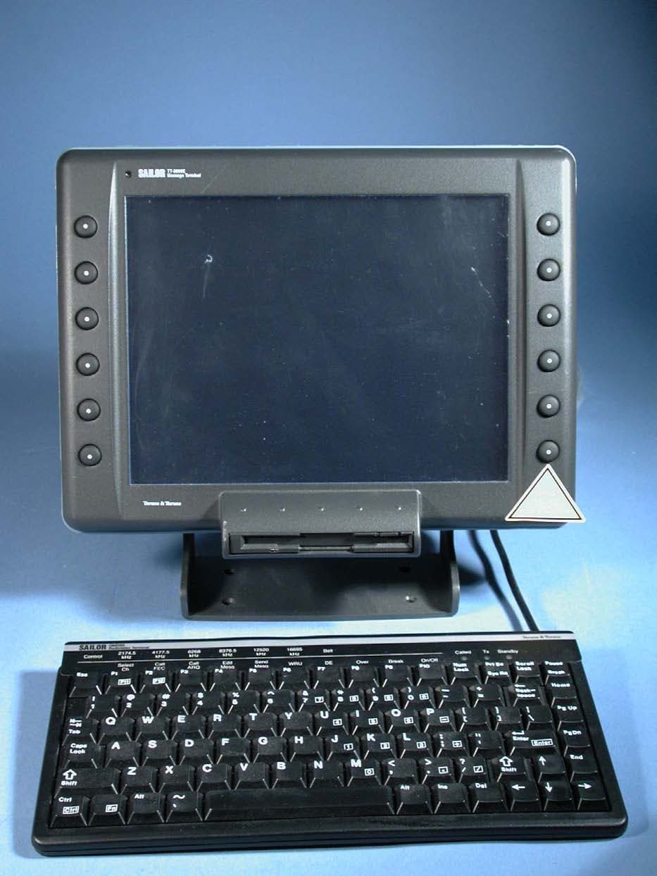
Click to zoom
Application Details
- Equipment Class
- GHF - Part 80 HF Transmitter (GMDSS)
- Date of Grant
- Feb 06, 2008
- Application Purpose
- Original Equipment
- Date of Application
- Feb 06, 2008
- Equipment Note
- Sailor System 5000 150W GMDSS MF/HF SSB DSC NBDP
- Frequency Range
- 1.60000000 - 27.50000000
- Company
- Thrane & Thrane A/S
- Country
- Denmark
Documents & Files
Document Text
Text extracted from the exhibit documents filed with the FCC. Open a document above to read the original.
Users Manual
SAILOR AP5065 Alarm Panel INSTALLATION MANUAL 1 0715 Disclaimer Any responsibility or liability for loss or damage in connection with the use of this product and the accompanying documentation is disclaimed by Thrane & Thrane. The information in this manual is provided for information purposes only, is subject to change without notice, may contain errors or inaccuracies, and represents no commitment whatsoever by Thrane & Thrane. This agreement is governed by the laws of Denmark. Manuals issued by Thrane & Thrane are periodically revised and updated. Anyone relying on this information should satisfy himself/herself as to the most current version. Providers with access to Thrane & Thrane’s Extranet may obtain current copies of manuals at: http:// extranet.thrane.com. Thrane & Thrane is not responsible for the content or accuracy of any translations or reproductions, in whole or in part, of this manual from any other source. Contents Introduction.............................................................................................................................. 3 General Description............................................................................................................. 3 Technical Data..................................................................................................................... 4 Operation................................................................................................................................... 5 Distress................................................................................................................................5 General................................................................................................................................. 6 Installation................................................................................................................................. 7 Connector overview............................................................................................................. 7 Auxiliary interfaces............................................................................................................... 7 Interconnecting more Alarm Panels.................................................................................... 8 Wiring interconnected Alarm Panels................................................................................... 9 Wiring to VHF 1 or VHF 2.................................................................................................. 10 Wiring to MF/HF................................................................................................................. 11 Wiring to Inmarsat-C 1 or Inmarsat-C 2 (mini-C).............................................................. 12 Wiring to 24V DC Supply................................................................................................... 13 Outline and dimension....................................................................................................... 14 2 0715 3 0736 Introduction General Description The GMDSS Distress Alarm Panel is used for remote initiation of distress alert transmissions and visible and audible indication of incoming distress and urgency calls on VHF, MF/HF, and Inmarsat-C. Normally it is installed on the bridge at the conning position. The Alarm Panel contains three main sections, intended for connection to System 5000 VHF, System 5000 MF/HF equipment, and Inmarsat-C SES equipment. All sections work inde- pendently and all control signals are galvanically isolated by opto-couplers. For Inmarsat-C and VHF, the Alarm Panel has duplicated connections allowing two units of each system to be supported simultaneously. Each section includes a push button for distress alert initiation, and a distress annunciator for indication of distress alert transmission in progress or distress or urgency calls received. Additionally there is an annunciator for indication of equipment type. This is switched on when the appropriate transceiver has been sensed by the Alarm Panel. If a distress alarm is initiated on a system with duplicated units, only one of the units will send the alarm. The selected unit is indicated on the display. To protect against inadvertent activation the distress buttons are protected by spring loaded transparent covers. A button must be kept pressed for 5 seconds before the distress alert is initiated, during which time the audible alarm is beeping and the distress button is flashing. The Alarm Panel is supplied from 24 V DC supply voltage (21 V to 32 V). The input is reverse polarity protected. 4 0715 Technical Data General Illuminated red distress button with transparent cover for each section. Indicator Alarm Panel with distress annunciator and status information for each connected unit. Audible alarm for indication of distress alert transmission in progress, or distress or urgency calls received. Dimmer push button for controlling light intensity in the indicator Alarm Panel. Mute push button for resetting the audio alarm. Test push button for verification of indicators, audible alarm and push buttons. All distress functions work fully independent of each other. All control signals are galvanically isolated by opto-couplers. The indication line in the display goes off if the connection to the associated transceiver is broken. When the connection is re-established it may take up to 20 seconds before it is indicated in the display. Supply Voltage:24 V DC (21 V to 32 V) Current consumption:max.100 mA Operating temperature range:-20°C to +55°C Compass safe distance:Standard: 0.9 m. Steering: 0.6 m. 5 0736 Operation Distress Sending Distress Alert Open the key cover and press the ‘DISTRESS’ push button for minimum 5 seconds. The alert button and the selection annunciator for the active unit flashes, and the buzzer sounds periodically. When the distress alert transmission starts, the distress button and the selection annunciator …
Text truncated - open the document above for the full version.
Users Manual
Radiotelex USER MANUAL II RADIOTELEX Disclaimer Any responsibility or liability for loss or damage in connection with the use of this product and the accompanying documentation is disclaimed by Thrane & Thrane. The information in this manual is provided for information purposes only, is subject to change without notice, may contain errors or inaccuracies, and represents no commitment whatsoever by Thrane & Thrane. This agreement is governed by the laws of Denmark. Manuals issued by Thrane & Thrane are periodically revised and updated. Anyone relying on this information should satisfy himself/herself as to the most current version. Providers with access to Thrane & Thrane’s Extranet may obtain current copies of manuals at: http://extranet.thrane.com. Thrane & Thrane is not responsible for the content or accuracy of any translations or reproductions, in whole or in part, of this manual from any other source. 0725 III RADIOTELEX Contents 1Introduction...........................................................................................1-1 1.1General information................................................................................1-1 Radiotelex system..................................................................................1-1 GMDSS..................................................................................................1-1 Communication concept.........................................................................1-1 1.2Terminology............................................................................................1-2 General telex terms................................................................................1-2 Radiotelex terms ....................................................................................1-3 2Operation..............................................................................................2-1 2.1Introduction.............................................................................................2-1 Forms and fields.....................................................................................2-1 Function keys.........................................................................................2-2 General functions...................................................................................2-3 Fast keys................................................................................................ 2-3 Password ................................................................................................ 2-4 2.2Terminals................................................................................................ 2-4 2.3Terminal function keys............................................................................2-5 Function keys when ‘standby’.................................................................2-5 Function keys when not ‘standby’..........................................................2-7 2.4Backups.................................................................................................. 2-8 To make a backup .................................................................................. 2-8 Background information on backups......................................................2-8 Backup policy.........................................................................................2-8 Radiotelex on hard disk..........................................................................2-9 2.5Transmission.......................................................................................... 2-9 2.6Scanning................................................................................................. 2-10 2.7Message handling..................................................................................2-11 Import of message.................................................................................2-12 Export of message.................................................................................2-12 2.8Subscriber handling...............................................................................2-12 Subscriber edition in general.................................................................2-13 Subscriber parts .....................................................................................2-13 Hiding and recovering subscribers........................................................2-14 2.9VIEW function.........................................................................................2-14 2.10Distress..................................................................................................2-15 Distress mode........................................................................................2-16 Distress Transmission............................................................................2-17 Distress SCAN function.........................................................................2-17 Distress VIEW function..........................................................................2-17 2.11Status messages....................................................................................2-18 0725 IV RADIOTELEX 0725 3Installation and configuration.............................................................3-1 3.1Installation..............................................................................................3-1 System wirings.......................................................................................3-1 Modem setup..........................................................................................3-3 Factory reset..........................................................................................3-6 Printer setup...........................................................................................3-6 Ship name..............................................................................................3-6 Setting up subscribers.............................................................…
Text truncated - open the document above for the full version.
Users Manual
AC Power Supply T e c h n i c a l M a n u a l Valid for: PS4655 PS4665 P2420 Please Note: Any responsibility or liability for loss or damage in connection with the use of this product and the accompanying documentation is disclaimed. The information in this quick guide is furnished for informational use only, is subject to change without notice, may contain errors or inaccuracies, and represents no commitment whatsoever. This agreement is governed by the laws of Denmark. Doc. No.: M4655COM Issue: D/0549 Contents AC Power Supply CONTENTS AC POWER SUPPLY 1 INTRODUCTION 1-1 1.1 GENERAL DESCRIPTION 1-1 1.2 TECHNICAL DATA 1-1 2 TECHNICAL DESCRIPTION 2-1 2.1 PRINCIPLE OF OPERATION 2-1 3 INSTALLATION 3-1 3.1 OUTLINE AND DIMENSIONS 3-1 3.2 MOUNTING POSSIBILITIES 3-1 3.3 INSTALLATION WIRING 3-2 3.4 BLOCK DIAGRAM 3-3 3.5 AC SUPPLY VOLTAGE SETTING 3-4 3.6 CONNECTIONS 3-4 4 SCHEMATIC DIAGRAM AND COMPONENT LOCATION 4-1 4.1 POWER SUPPLY UNIT 4-1 5 PARTS LIST 5-1 6 ACCESSORIES INCLUDED 6-1 0048 1-1 1 Introduction AC Power Supply AC POWER SUPPLY 1 INTRODUCTION 1.1 GENERAL DESCRIPTION The AC Power Supply is designed as a stand alone automatic AC Power Supply with automatic switch-over to 24V battery supply. The AC Power Supply is designed with four separately fused output lines to ensure independent supply for connected equipment. Furthermore AC Power Supply includes the following features: • 115V/230V selectable input. • Encapsulation class IP22. • Galvanic isolated AC alarm output. • Protected Battery monitoring output. • Easy connection. • Easy access to fuses. • Vertical or horizontal mounting. • IEC 945 approved. 1.2 TECHNICAL DATA AC input voltages: 115V, range 88V - 132V or 230V, range 176V - 264V. Manual setting. AC input frequency: 50/60 Hz ± 6% DC output voltage: 29V ± 0.5V. DC output current: 13A continuous. 17A for 15 minutes. 25A for 1 minute. Duty-cycle 10%. Battery monitoring: Protected output. AC failure output: Relay contacts 5-50mA, 10-32V. Closed in alarm condition. Alarm in case of AC supply failure. Protection: The AC Power Supply output is current limited and protected against short circuit, over voltage and over temperature. Operating temperature: - 20° to + 55° C. Dimensions: HxWxD: 110x370x260 mm. Weight: Approx. 5 kg. Compass safe distance: Standard: 1.4 m. Steering: 1.0 m 0549 1-2 1 Introduction AC Power Supply 0048 2-1 2 Technical Description AC Power Supply 2 TECHNICAL DESCRIPTION 2.1 PRINCIPLE OF OPERATION The AC Power Supply contains an input filter followed by a rectifier (230V)/voltage doubler (115V) circuit producing an unregulated DC voltage which is converted to 29V in a push-pull converter. A regulator optically isolated form the driver circuit then adjusts the output into a constant voltage. The output DC voltage is galvanically isolated from the input and the chassis (ground). The four DC outputs are connected to the battery using it as source if an AC line failure or failure in the unit occurs. As the AC line recovers the AC Power Supply is again source for the four DC outputs. This sequence is controlled by the switch over circuit. 0549 2-2 2 Technical Description AC Power Supply 0048 3-1 3 Installation AC Power Supply 3 INSTALLATION 3.1 OUTLINE AND DIMENSIONS 370mm Mounting, 4 holesø7mm 37670 160mm 260mm 331mm 110mm Cable entry in bottom 350mm 1) 1) 2) 1) 0048 37669 4 screws M5 x 12 4 screws M5 x 12 3.2 MOUNTING POSSIBILLITIES 1) Space for air fl ow min. 200mm 2) Space for cable 250mm 3-2 3 Installation AC Power Supply 3.3 INSTALLATION WIRING 0048 20A - + - + - + 10A10A10A10A10A DC 1 10A +- 20A 30A +- BATTERY CHARGE X4 X5 X9X10X2X1 FLOATMAIN AC ALR LIGHT AC ALR VBAT- DC 2 DC 3 VBAT+ NL X14X13X15 -+ Battery voltage monitor AC alarm Line Neutral Earth 37594 * Max 20A - 29V DC out* Max 10A - 29V DC out* Max 10A - 29V DC out * Max 10A - Emergency light 230/115V AC input Fuse *Note that total output must not exceed specifications 230V/8AT F13 115V/15AT F12 BATTERY CHARGER 3-3 3 Installation AC Power Supply 3.4 BLOCK DIAGRAM INPUT RECTIFIER/ FILTER AC-ALARM CURRENT TRAFO PUSH-PULL STAGE CURRENT FEEDBACK DRIVER STAGE PWM SLOPE COMP. POWER TRAFO OUTPUT RECTIFIER/ FILTER SWITCH OVER AUXILLARY SUPPLY OPTO OTPOVP OPTO BATTERY MONITOR 37671 230V AC AC ALR VBAT BATTERY DC 1 LIGHT DC 2 DC 3 REGULATOR 115V AC 0048 3-4 3 Installation AC Power Supply 0048 3.5 AC SUPPLY VOLTAGE SETTING Before connecting the AC Power Supply to the AC mains, check that the AC Power Supply is set to the correct voltage and that the fuse rating corresponds to the setting used. The voltage setting is selected by changing the fuse located under the front cover. The equipment is normally set to 230V. To select a different voltage insert the appropriate fuse. Take care that the power is switched off before changing the fuse. Fuse setting for 230V Fuse setting for 115V Caution: Incorrect setting of the mains voltage may damage the AC Power Supply assembly. 3.6 CONNECTIONS AC INPUT The AC supply leads are connected to the terminal block as indicated. Screened power supply cable may be used as required by some administrations. The cable is fastened and the screen connected by a cable clamp on the main chassis below the terminal block. Recommended cable type: 3 x 1.5 mm² screened. Setting Voltage range Fuse rating 230V 176 - 264V F13 - 8AT NL X14X13X15 37686 230V/8AT F13 115V/15AT F12 F13 RF ground Terminal Designation Description X13 N Neutral X14 L Line X15 Protective Earth Setting Voltage range Fuse rating 115V 88 - 132V F12 - 15AT NL X14X13X15 37725 230V/8AT F13 115V/15AT F12 F12 RF ground 3-5 3 Installation AC Power Supply Terminal Designation Description X9 BATTERY - Input from Battery X10 BATTERY + Max. cable length to battery 7 metres 11 metres 17 metres Recommended Screened multiwire 2 x 10 mm² 2 x 16 mm² 2 x 25 mm² External fuses 40A 50A 63A OUTPUTS Terminal Designation Description X1 DC 1 + 29V DC or Battery X2 DC 1 - voltage in case of AC supply failure Terminal Designation Description X5 - 1 LIGH…
Text truncated - open the document above for the full version.
Users Manual
S.P. RADIO A/SAALBORGDENMARK TECHNICAL MANUAL FOR H1252B DC PRINTER Please note Any responsibility or liability for loss or damage in connection with the use of this product and the accompanying documentation is disclaimed. The information in this manual is furnished for informational use only, is subject to change without notice, may contain errors or inaccuracies, and represents no commitment whatsoever. This agreement is governed by the laws of Denmark. Doc. no.: M1252BGBIssue: A/0146 CONTENTS PART I 1GENERAL INFORMATION1-1 1.1OKI DOCUMENTATION1-1 2INSTALLATION2-1 2.1MOUNTING POSSIBILITIES, DIMENSIONS AND DRILLING PLAN2-1 2.2H1252B PRINTER WITH MOUNTING KIT H1250 OR GMDSS CONSOLE H21922-2 3PARTS LIST3-1 CONTENTS PART II 1GENERAL INFORMATION1-1 1.1INTRODUCTION1-1 1.2PRINCIPLE OF OPERATION1-1 1.3TECHNICAL DATA1-1 2MAINTENANCE/MODIFICATION2-1 2.1DISASSEMBLING TO REMOVE THE MAINS TRANSFORMER2-1 2.2DISASSEMBLING AND MOUNTING OF THE ON-OFF SWITCH2-1 2.3MOUNTING THE DC POWER SUPPLY AND REASSEMBLING2-2 2.4ELECTRICAL CONNECTIONS2-4 3SERVICE3-1 3.1PRINTER SELFTEST3-1 3.2MODULE CHECK OF THE DC POWER SUPPLY3-1 3.3CHECK AFTER REPAIR3-1 4MECHANICAL DISASSEMBLING OF PRINTER4-1 5CIRCUIT DESCRIPTION5-1 5.1DC POWER SUPPLY5-1 6PARTS LIST6-1 H1252B 9737 CONTENTS 1GENERAL INFORMATION1-1 1.1OKI DOCUMENTATION1-1 PART I/H1252B PAGE 1-1 1 GENERAL INFORMATION H1252B Hardcopy printer is an OKI MICROLINE 182/280 printer with built-in DC power supply for 10.5- 32V DC operation. H1252B is as standard delivered with a Roll Paper Stand, other paper types can also be used, please refer to the OKI manual for detailed information. H1252B is as standard delivered with the mounting kit H1250, it can also be mounted on the H2192 GMDSS Console using the mounting plate which is delivered together with the H2192 GMDSS Console. Paper roll, Power cable and Centronics cable are supplied with the H1252B. 501279 501274 1.1 OKI DOCUMENTATION PART I/H1252B 501278 CONTENTS 2INSTALLATION2-1 2.1MOUNTING POSSIBILITIES, DIMENSIONS AND DRILLING PLAN2-1 2.2H1252B PRINTER WITH MOUNTING KIT H1250 OR GMDSS CONSOLE H21922-2 PART I/H1252B PAGE 2-1 2INSTALLATION 2.1 MOUNTING POSSIBILITIES, DIMENSIONS AND DRILLING PLAN Mounting kit H1250 240 mm 280 mm371 mm 28709 28711 4 pcs ø6 mm 300 mm 341 mm 371 mm 290 mm Mounting kit H2192 442 mm325 mm 240 mm 28699 428 mm 442 mm 2 pcs 4 mm 28710 118.5 mm 256 mm PART I/H1252B 2 INSTALLATIONPART I/H1252B 2.2 H1252B PRINTER WITH MOUNTING KIT H1250 OR GMDSS CONSOLE H2192 H1252B printer with H1250 PAGE 2-2 H1252B printer with H2192 28697 Screw, 1 piece M4 x 10 Washers, 2 pieces M4 Self-cutting screws, 2 pieces 4.2 x 25 Screws, 3 pieces M4 x 20 428 mm 442 mm 118.5 mm 256 mm 28641 Self-cutting screws, 4 pieces 4.2 x 25 Screws, 3 pieces M4 x 20 Washers, 4 pieces M4 Screw, 1 piece M4 x 10 300 mm 341 mm 290 mm 371 mm CONTENTS 3PARTS LIST3-1 PART I/H1252B PAGE 6-1 3PARTS LIST PART I/H1252B OKI MICROLINE u182/280 WITH 24V DC POWER SUPPLY ECI A/S 821252 POSITIONDESCRIPTIONMANUFACTORTYPEPART NO. VARIOUS BOTTOM PLATE PRINTER 182 H1250 ECI A/S 1-0-24747 / 140.956 200606 VARIOUSTELEX ROLL B=20.9cmL=120m SINGLE LAYERNCRArt.Nr: 230.10047.830 VARIOUS INTERCONNECTION CABLE 25 POLES SUB D-CENTRONIC RADIO PARTS Art.Nr: 393535 56.013 VARIOUSPOWER CABLE 3 POLE H1252B2000mm (T&T M061-101028)MONTRONICS3-0-2847856.066 Art.Nr: M024 VARIOUS SCREW KIT ECI A/S 700654 700654 VARIOUS SPARE FUSES FOR H1252B H1252B ECI A/S 0-0-27246 727246 VARIOUS 10.5-32V DC POWER SUPPLY FOR OKI PRINTER u182/u280 ECI A/S 0-0-28515 728515 VARIOUS MANUAL FOR H1252B ENGLISH ECI A/S M1252BGB CONTENTS 1GENERAL INFORMATION1-1 1.1INTRODUCTION1-1 1.2PRINCIPLE OF OPERATION1-1 1.3TECHNICAL DATA1-1 PART II/H1252B PART II/H1252B PAGE 1-1 1GENERAL INFORMATION 1.1 INTRODUCTION This section gives you all the necessary informations to maintaine the DC power supply module. It also specify how to modify the printer to operate on DC supply instead of AC supply. 1.2 PRINCIPLE OF OPERATION The power supply module is constructed to operate from a battery voltage of 10.5V DC to 32V DC to deliver the necessary voltages for the printer. The voltage conversion takes place in a “flyback” switch converter, which is controlled by a current mode controller. The regulation of the output voltage is controlled via a separate winding of the transformer, which also deliveres the power for the control circuit. At the input and at the output are placed filters to suppress the switch noise. BLOCKDIAGRAM PWM INPUT FILTERCONVERTER SWITCH FILTER OUTPUT CONTROL CIRCUIT + - 10.5V....32V +30V +10V 28480 1.3 TECHNICAL DATA Input voltage range: 10.5V DC to 32V DC Current consumption: max. 4.5A (fuse = 6.3AT) Output voltages: 10V DC / 0.3A : 30V DC / 0.8A Noise from input terminals: better than CEPT Rec. T/R 34-01 On/off: by switch Operating temperature: -15 o C to +55 o C CONTENTS 2MAINTENANCE/MODIFICATION2-1 2.1DISASSEMBLING TO REMOVE THE MAINS TRANSFORMER2-1 2.2DISASSEMBLING AND MOUNTING OF THE ON-OFF SWITCH2-1 2.3MOUNTING THE DC POWER SUPPLY AND REASSEMBLING2-2 2.3.1MOUNTING OF THE DC POWER SUPPLY2-2 2.3.2MODIFICATION OF THE PRINTER MAIN CONTROL BOARD2-3 2.3.3REASSEMBLING OF THE PRINTER2-3 2.4ELECTRICAL CONNECTIONS2-4 PART II/H1252B PAGE 2-1 2MAINTENANCE/MODIFICATION This section is intended for use when modifying the printer to operate from DC supply instead of 220V AC supply. 2.1DISASSEMBLING TO REMOVE THE MAINS TRANSFORMER Remove the access cover by lifting up rear edge. Pull out the platen knob. Remove the two screws. Remove the top cover by lifting up the front and pushing it backward. Remove the transformer output cable from the printer Main Control Board. Remove the ground strap screw, but keep it for later use. Remove the two screws, that fix the transformer, but keep them for later use. Remove the transformer assembly with power PCB and AC cord receptable by lifting upwards. Remove the 220V~ label located at the panel cut out for the AC cord receptable. 2 45 3 3 28560 1 2.2DISASSEMBLING AND M…
Text truncated - open the document above for the full version.
Users Manual
SAILOR CU5100 MF/HF Radiotelephone USER MANUAL Introduction Congratulations on your new SAILOR CU5100 MF/HF maritime radio telephone with built-in DSC (Digital Selective Calling) system, fulfilling the highest international standards for marine MF/HF communication and safety procedures. The transceiver is born with a 2187,5kHz DSC watch receiver forming an ideal system for MF GMDSS installations. The transceiver can easily be upgraded for 6 channel scanning DSC watch receiver and Telex operation to comply with MF/HF requiements in sea area A3. If connected to a GPS or other maritime navigation system it can automatically include the true UTC time and your position in its DSC distress messages. For an explanation of DSC, see page 2. This SAILOR marine equipment is a part of the modular system 5000 which also includes a HF single sideband radiotelephone. SAILOR marine equipment is specially designed for the extremely rugged conditions on bord a ship, based on more than 50 years’ experience with all kinds of boats, from small pleasure crafts, over fishing boats working under all climatic conditions, to the biggest ships. SAILOR ® is one of the worlds leading manufacturers of maritime radiocommunication equipment - a position which has been maintained by means of constant and extensive product development. We have a worldwide network of dealers with general agencies in more than 80 countries. All our dealers are specially trained to service all your SAILOR ® products. About this manual This manual is for the daily user of the system. Additionally, it includes a section on the installation procedures, and - on page iii - standard distress procedures. We highly recom- mend you to read the manual before you start using the equipment. Notice: There may be some minor differences in the graphic layout of the manual compared to the physical device. Disclaimer Any responsibility or liability for loss or damage in connection with the use of this product and the accompanying documentation is disclaimed by Thrane & Thrane. The information in this manual is provided for information purposes only, is subject to change without notice, may contain errors or inaccuracies, and represents no commitment whatsoever by Thrane & Thrane. This agreement is governed by the laws of Denmark. Manuals issued by Thrane & Thrane are periodically revised and updated. Anyone relying on this information should satisfy himself/herself as to the most current version. Providers with access to Thrane & Thrane’s Extranet may obtain current copies of manuals at: http:// extranet.thrane.com. Thrane & Thrane is not responsible for the content or accuracy of any translations or reproductions, in whole or in part, of this manual from any other source. i 0725 ii Abbreviations used in this manual ADDRAddress AGCAutomatic Gain Control AMAmplitude Modulation ARQAutomatic Repetition reQuest CLRFClarify CUControl Unit DIRTLXDirect Telex DSCDigital Selective Calling ETSIEuropean Telecommunications Standards Institute FECForward Error Correction GAGo Ahead GMDSSGlobal Maritime Distress and Safety System GPSGlobal Positioning System HFHigh Frequency H3ESingle sideband - full carrier IMOInternational Maritime Organisation IRSInformation Receiving Station ISSInformation Sending Station ITUInternational Telecommunication Union J3ESingle sideband - no carrier MFMedium Frequency MMSIMaritime Mobile Ship Identification MOMJust a moment please MSGMessage NBDPNarrow Band Direct Printing PTTPush-To-Talk RF-GReceiver Frequency Gain RxReceive SSBSingle Side Band TELTelephony TxTransmit UTCCo-ordinated Universal Time VHFVery High Frequency WRUWho Are You 0725 Quick DSC distress call (only for emergency use) 1. If necessary, switch on by pressing the ON/OFF button 2. Lift up the lid covering the orange key and press for 3 seconds. 3. The distress will be accompanied by a sound. Distress message is sent at the continuous tone. 4. Unless stopped manually, by pressing the CANCEL softkey or switching the unit off, the distress call is automatically repeated every 3½-4½ minutes until distress acknowledge- ment is received. Wait for distress acknowledgement and start mayday procedure. If an alarm panel is connected the MF/HF DISTRESS button on this unit will have the same functionality. All further handling should continue in front of your main MF/HF DSC. Mayday procedure When DSC distress acknowledgement is received after you have pressed DISTRESS, or if you otherwise need to commence distress traffic via radiotelephony on the distress traffic frequency, follow this procedure: •the distress signal MAYDAY, spoken three times; •the words THIS IS; •the NAME of the vessel in distress, spoken three times; •the CALL SIGN or other identification; •the MMSI if needed; •the POSITION given as the LATITUDE and LONGITUDE or with respect to known geographical location, •the NATURE of the distress; •the kind of ASSISTANCE required; and •any other useful INFORMATION Upon reception of a DSC distress alert from another ship in distress, you should acknowl- edge the receipt by radiotelephony on the distress traffic frequency, by doing the following: •the distress signal MAYDAY; •the words THIS IS; •the NAME of the vessel in distress, spoken three times; •the NAME or other identification of own ship, spoken three times; •“RECEIVED MAYDAY”. Transmission of DSC distress alert on MF/HF (2, 4, 6, 8, 12, 16 MHz) 2187.5 kHz,4207.5 kHz,6312.0 kHz,8414.5 kHz,12577.0 kHz, 16804.5 kHz 0725 iii 12345 678910 The MF/HF at a glance (CU5100) 1. Display. 2. Dimming button. 3. Mode button. Toggles between SSB TELEPHONY, AM BROADCAST, DSC, TELEX (Option) and SSB REMOTE 4. Menu button. Access to the menu system. 5. Keyboard. 6. Loudspeaker. 7. DISTRESS button. Protected by shield. To use, lift the shield and press for 3 seconds. 8. Soft keys. The function of each key is described in its respective field in the display above each key. 9. Adjust/Tune. Multi purpose rotary knob. Controls backlight, fr…
Text truncated - open the document above for the full version.
Contact Information
Applicant
Niels Peter Agdal(Mr.)
Test Firm
Kiwa Nederland B.V.Willem Jong
[email protected]+31 889983621
Technical Specifications
| # | Rule Parts | Frequency Range | Power Output | Emission | Tolerance |
|---|---|---|---|---|---|
| 2 | 80.1101(c)(4) | 1.6 MHz - 27.5 MHz | 150 W | 300HJ2B | 0.3 ppm |
Other Applications from Thrane & Thrane A/S

ROJ-8033A
Aug 22, 2024Satellite IP router
Equipment Class
DTS - Digital Transmission System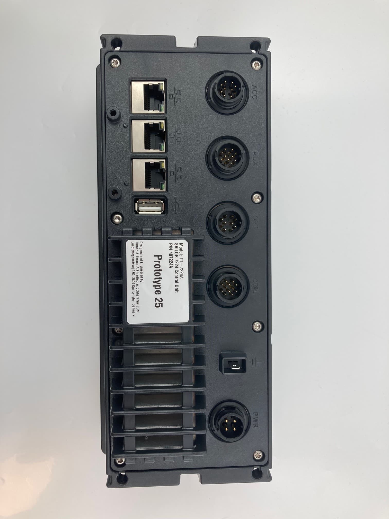
ROJ7226
Nov 24, 2022SAILOR 7222 VHF DSC Class A
Equipment Class
GVH - Part 80 VHF Transmitter (GMDSS)
ROJ-3723A
Mar 24, 2020Inmarsat landmobile terminal
Equipment Class
TNB - Licensed Non-Broadcast Station Transmitter
ROJ-3711A
May 01, 2015Satellite Terminal
Equipment Class
DTS - Digital Transmission System
ROJEXPLORER-710
Jun 06, 2014TT-3720B Land-portable broadband terminal for Inmarsat satellite system Consists of TT-3732B Transceiver and TT-3703B Antenna
Equipment Class
TNB - Licensed Non-Broadcast Station Transmitter