ROL-ASI41010000Wireless USB Dongle
Astarte Technology Co., Ltd.
Click to zoom
Application Details
- Equipment Class
- DTS - Digital Transmission System
- Date of Grant
- Jan 20, 2005
- Application Purpose
- Original Equipment
- Date of Application
- Jan 20, 2005
- Equipment Note
- Wireless USB Dongle
- Frequency Range
- 2412.00000000 - 2462.00000000
- Company
- Astarte Technology Co., Ltd.
- Country
- Taiwan
Documents & Files
Document Text
Text extracted from the exhibit documents filed with the FCC. Open a document above to read the original.
Users Manual
1 54Mbps 802.11b/g SoftGate Wireless AP/Router solution User’s Guide Version QG 1.75 December 2004 Copyright 2004. All Rights Reserved. Document Version: QG 1.75 All trademarks and trade names are the properties of their respective owner. 2 Federal Communication Commission Interference Statement This equipment has been tested and found to comply with the limits for a Class B digital device, pursuant to Part 15 of the FCC Rules. These limits are designed to provide reasonable protection against harmful interference in a residential installation. This equipment generates, uses and can radiate radio frequency energy and, if not installed and used in accordance with the instructions, may cause harmful interference to radio communications. However, there is no guarantee that interference will not occur in a particular installation. If this equipment does cause harmful interference to radio or television reception, which can be determined by turning the equipment off and on, the user is encouraged to try to correct the interference by one of the following measures: - Reorient or relocate the receiving antenna. - Increase the separation between the equipment and receiver. - Connect the equipment into an outlet on a circuit different from that to which the receiver is connected. - Consult the dealer or an experienced radio/TV technician for help. FCC Caution: Any changes or modifications not expressly approved by the party responsible for compliance could void the user's authority to operate this equipment. This device complies with Part 15 of the FCC Rules. Operation is subject to the following two conditions: (1) This device may not cause harmful interference, and (2) this device must accept any interference received, including interference that may cause undesired operation. IMPORTANT NOTE: FCC Radiation Exposure Statement: This equipment complies with FCC radiation exposure limits set forth for an uncontrolled environment. End users must follow the specific operating instructions for satisfying RF exposure compliance. This transmitter must not be co-located or operating in conjunction with any other antenna or transmitter. Remark: Wireless USB Dongle is limited in Ch1~Ch11 by specified firmware controlled in U.S.A. 3 Chapter 1. General Introduction This Chapter provides a general overview of the SoftGate AP/Router's features and specifications. Thank you for choosing SoftGate® wireless solution. SoftGate® is the first AP-less series family product to utilize an existing computer to become a wireless AP and Router with the management capability. SoftGate® can provide four functions (4- in-1): Router, AP, Bridge, and WLAN Client. Through SoftGate®, users can share internet connection and PC’s resources such as files, Hard Disk storage, MP3 music, printers, CD/DVD ROM...etc. A wireless Local LAN connection can be easily built using SoftGate® technology. SoftGate® is the first technology that truly removes the limitation of wireless base station (AP/Router). There are two major functions added in this version: Client Management and Time Management. Client Management SoftGate® has a unique patent for user to manage individual client. SoftGate® console screen will update immediately if there is any new client login to SoftGate®. This feature is not possible to accomplish by using a traditional AP(or dedicated hardware AP). For traditional AP, user must go through a complicated procedure in order to get only the client’s MAC address. Traditional or dedicated hardware AP can get only the client’s MAC address. SoftGate®, on the other hand, can easily provide the full client information including Computer Name, IP address and MAC address. Time Management SoftGate® is able to let user manage the client by time. SoftGate® is not only provide the limiting hours that client can access SoftGate® but also the exact hour to login. Most importantly is that SoftGate® operates on each individual client. Hence, the operation on the client will not disturb other clients normal operation. 1.1 SoftGate Features 1.1 z 4 in 1 Device— Integrates Router, AP, Bridge, and WLAN client into your system. z Easy Installation & Expansion— Simple, affordable and flexible solution break through your wireless limitation. z Complete Mobility— Small size, portable wireless AP, Router, and WLAN client. z Mode Switch— Mode switching can be as easy as one mouse click. It will take less than one minute to switch between the mode operations. z Wireless Bridge — SoftGate® can share the Internet connection via another standard wireless device in the same system, It's useful for hotspot (Mobile city) network environment. z Intelligent device— Auto-detect and configuration at installation. There is a minimum to no knowledge required to setup a wireless environment. In the client mode, SoftGate ® will auto detect and connect to available AP/Router. z Time Management —SoftGate ® can manage clients according to time limitation. You can easily setup a time limitation for each individual user. The time operation on each individual user will not disturb other clients’ normal operation. z Share Folder— SoftGate ® will make share folders easier than ever. SoftGate® instantaneously allow user to share the Hard Disk information with the clients. It will assume maximum allowance to access the Hard Disk. Once, the SoftGate® is shutdown, than the shared folders turn off automatically. It will prevent the information being access without user awareness. z Save and Load— Each configuration can be saved independently. User can re-load the profile at the proper environment. z Flexible WLAN adapter selected— SoftGate ® can let users select to share different broadband Internet connection, such as RJ45, wireless connection, dial-up, or 1394 connection. z Support multiple languages— SoftGate ® can let users to choose different language at installation. Users is also able to change to the prefer language after completed installation. z Computer name and IP— So…
Text truncated - open the document above for the full version.
External Photos
Page 1 CONSTRUCTION PHOTOS OF EUT Page 2
ID Label/Location Info
FCC ID Label Location
Internal Photos
Page 3 Page 4 Page 5 Page 6
Operational Description
FCC ID: ROL-ASI41010000 Report No. RF931206L15 Operational Description This device is a Wireless USB Dongle which operates in the 2.4GHz frequency spectrum with throughput of up to 54Mbps which OFDM technique will be applied. If the signal to noise radio is too poor which could not support 54Mbps, the 11Mbps data rate with DSSS technique will be applied. The transmitter of the EUT is powered by host equipment. The antenna is Chip antenna without antenna connector. The other instruction, please have a look at the users manual.
RF Exposure Info
FCC ID: ROL-ASI41010000 Report No: SA931206L15 1 RF EXPOSURE REPORT REPORT NO.: SA931206L15 MODEL NO.: ASI4101 ACCORDING: FCC Guidelines for Human Exposure IEEE C95.1 APPLICANT: Astarte Technology Co., Ltd. ADDRESS: 11F, No. 166, Dah-Yeh RD., Peitou 112, Taipei, Taiwan, R.O.C. ISSUED BY: Advance Data Technology Corporation LAB ADDRESS: No. 47, 14th Ling, Chia Pau Tsuen, Lin Kou Hsiang 244, Taipei Hsien, Taiwan, R.O.C. TEST LOCATION: No. 19, Hwa Ya 2nd Rd., Wen Hwa Tsuen, Kwei Shan Hsiang, Taoyuan Hsien 333, Taiwan, R.O.C. FCC ID: ROL-ASI41010000 Report No: SA931206L15 2 RF Exposure Measurement (Portable Device) 1. Introduction In this document, we try to prove the safety of radiation harmfulness to the human body for our product. The limit for Maximum Permissible Exposure (MPE) specified in FCC 1.1310 is followed. The Gain of the antenna used in this product is measured in a Fully Anechoic Chamber (FAC) calibrated for antenna measurement in ADT, and also the maximum total power input to the antenna is measured. Through the Friis transmission formula and the maximum gain of the antenna, we can calculate the distance, away from the product, where the limit of MPE is reached. Although the Friis transmission formula is a far field assumption, the calculated result of that is an over-prediction for near field power density. We will take that as the worst case to specify the safety range. 2. RF Exposure Limit According to FCC 1.1310: The criteria listed in the following table shall be used to evaluate the environmental impact of human exposure to radio-frequency (RF) radiation as specified in 1.1307(b) LIMITS FOR MAXIMUM PERMISSIBLE EXPOSURE (MPE) Frequency Range (MHz) Electric Field Strength (V/m) Magnetic Field Strength (A/m) Power Density (mW/cm 2 ) Average Time (minutes) (A)Limits For Occupational / Control Exposures 300-1500......F/3006 1500-100,000......56 (B)Limits For General Population / Uncontrolled Exposure 300-1500......F/15006 1500-100,000......1.030 F = Frequency in MHz FCC ID: ROL-ASI41010000 Report No: SA931206L15 3 3. Friis Formula Friis transmission formula : Pd = (Pout*G) / (4*pi*r 2 ) where Pd = power density in mW/cm 2 Pout = output power to antenna in mW G = gain of antenna in linear scale Pi = 3.1416 R = distance between observation point and center of the radiator in cm If we know the maximum Gain of the antenna and the total power input to the antenna, through the calculation, we will know the MPE value at distance r. Ref. : David K. Cheng, Field and Wave Electromagnetics, Second Edition, Page 640, Eq. (11-133). 4 EUT Operating condition The software provided by Manufacturer enabled the EUT to transmit and receive data at lowest, middle and highest channel individually. 5. Classification This device is not fixed inside the host equipment that is classified as Portable Device. FCC ID: ROL-ASI41010000 Report No: SA931206L15 4 6 Conclusion No Evaluation required if power is below this threshold: F(GHz)mW Low2.412 High2.462 24.620 Maximum measured transmitter power: Pout (dBm)Pout (mW) Conducted Power11.1012.882 EIRP Power13.1020.417 *Note: The antenna is Chip antenna with 2.0dBi gain. Threshold for no SAR evaluation is 24.620mW Transmitter power is 20.417mW Conclusion: No SAR evaluation required since Transmitter Pout is below FCC threshold.
Test Report
FCC ID: ROL-ASI41010000 Report No.: RF931206L151Report Format Version 2.0.1 FCC TEST REPORT REPORT NO.: RF931206L15 MODEL NO.: ASI4101 RECEIVED: Dec. 06, 2004 TESTED: Dec. 24, 2004 ~ Jan. 14, 2005 ISSUED: Jan. 17, 2005 APPLICANT: Astarte Technology Co., Ltd. ADDRESS: 11F, No. 166, Dah-Yeh RD., Peitou 112, Taipei, Taiwan, R.O.C. ISSUED BY: Advance Data Technology Corporation LAB ADDRESS: No. 47, 14th Ling, Chia Pau Tsuen, Lin Kou Hsiang 244, Taipei Hsien, Taiwan, R.O.C. TEST LOCATION: No. 19, Hwa Ya 2nd Rd., Wen Hwa Tsuen, Kwei Shan Hsiang, Taoyuan Hsien 333, Taiwan, R.O.C. This test report consists of 65 pages in total. It may be duplicated completely for legal use with the approval of the applicant. It should not be reproduced except in full, without the written approval of our laboratory. The client should not use it to claim product endorsement by CNLA, A2LA or any government agencies. The test results in the report only apply to the tested sample. 0528 ILAC MRA FCC ID: ROL-ASI41010000 Report No.: RF931206L152Report Format Version 2.0.1 Table of Contents 1.CERTIFICATION ......................................................................................................4 2.SUMMARY OF TEST RESULTS ..............................................................................5 2.1MEASUREMENT UNCERTAINTY ...........................................................................6 3.GENERAL INFORMATION.......................................................................................7 3.1GENERAL DESCRIPTION OF EUT.........................................................................7 3.2DESCRIPTION OF TEST MODES...........................................................................8 3.3GENERAL DESCRIPTION OF APPLIED STANDARDS ..........................................8 3.4DESCRIPTION OF SUPPORT UNITS .....................................................................9 3.5CONFIGURATION OF SYSTEM UNDER TEST ....................................................10 4.TEST TYPES AND RESULTS ................................................................................ 11 4.1CONDUCTED EMISSION MEASUREMENT ......................................................... 11 4.1.1 LIMITS OF CONDUCTED EMISSION MEASUREMENT....................................... 11 4.1.2 TEST INSTRUMENTS ........................................................................................... 11 4.1.3 TEST PROCEDURES ............................................................................................ 12 4.1.4 DEVIATION FROM TEST STANDARD .................................................................. 12 4.1.5 TEST SETUP ......................................................................................................... 13 4.1.6 EUT OPERATING CONDITIONS ........................................................................... 13 4.1.7 TEST RESULTS ..................................................................................................... 14 4.2RADIATED EMISSION MEASUREMENT ..............................................................20 4.2.1 LIMITS OF RADIATED EMISSION MEASUREMENT............................................ 20 4.2.2 TEST INSTRUMENTS............................................................................................ 21 4.2.3 TEST PROCEDURES ............................................................................................ 22 4.2.4 DEVIATION FROM TEST STANDARD .................................................................. 22 4.2.5 TEST SETUP ......................................................................................................... 23 4.2.6 EUT OPERATING CONDITIONS ........................................................................... 23 4.2.7 TEST RESULTS ..................................................................................................... 24 4.2.8 TEST RESULTS (A) ............................................................................................... 25 4.2.9 TEST RESULTS (B) ............................................................................................... 28 4.36dB BANDWIDTH MEASUREMENT .....................................................................31 4.3.1 LIMITS OF 6dB BANDWIDTH MEASUREMENT ................................................... 31 4.3.2 TEST INSTRUMENTS............................................................................................ 31 4.3.3 TEST PROCEDURE............................................................................................... 32 4.3.4 DEVIATION FROM TEST STANDARD .................................................................. 32 4.3.5 TEST SETUP ......................................................................................................... 32 4.3.6 EUT OPERATING CONDITIONS ........................................................................... 32 4.3.7 TEST RESULTS (A) ............................................................................................... 33 4.3.8 TEST RESULTS (B) ............................................................................................... 36 4.4MAXIMUM PEAK OUTPUT POWER .....................................................................39 FCC ID: ROL-ASI41010000 Report No.: RF931206L153Report Format Version 2.0.1 4.4.1 LIMITS OF MAXIMUM PEAK OUTPUT POWER MEASUREMENT...................... 39 4.4.2 INSTRUMENTS...................................................................................................... 39 4.4.1 TEST PROCEDURES ............................................................................................ 40 4.4.2 DEVIATION FROM TEST STANDARD .................................................................. 40 4.4.3 TEST SETUP ......................................................................................................... 40 4.4.4 EUT OPERATING CONDITIONS ........................................................................... 40 4.4.3…
Text truncated - open the document above for the full version.
Test Setup Photos
FCC ID: ROL-ASI41010000 Report No.: RF931206L1563Report Format Version 2.0.1 5. PHOTOGRAPHS OF THE TEST CONFIGURATION CONDUCTED EMISSION TEST FCC ID: ROL-ASI41010000 Report No.: RF931206L1564Report Format Version 2.0.1 RADIATED EMISSION TEST
Contact Information
Applicant
James Yang(Marketing Manager)
Technical Contact
Advance Data Technology Corp.Ellis Wu
[email protected]+886-3-318-3232
No.19, Hwa Ya 2nd Rd., Kueishan · Taoyuan · Taiwan
Test Firm
Advance Data Tech. Corp. Hsin Chu EMCStephen Chen
Technical Specifications
| # | Rule Parts | Frequency Range | Power Output |
|---|---|---|---|
| 1 | 15C | 2.41 GHz - 2.46 GHz | 13.00 mW |
Other Applications from Astarte Technology Co., Ltd.
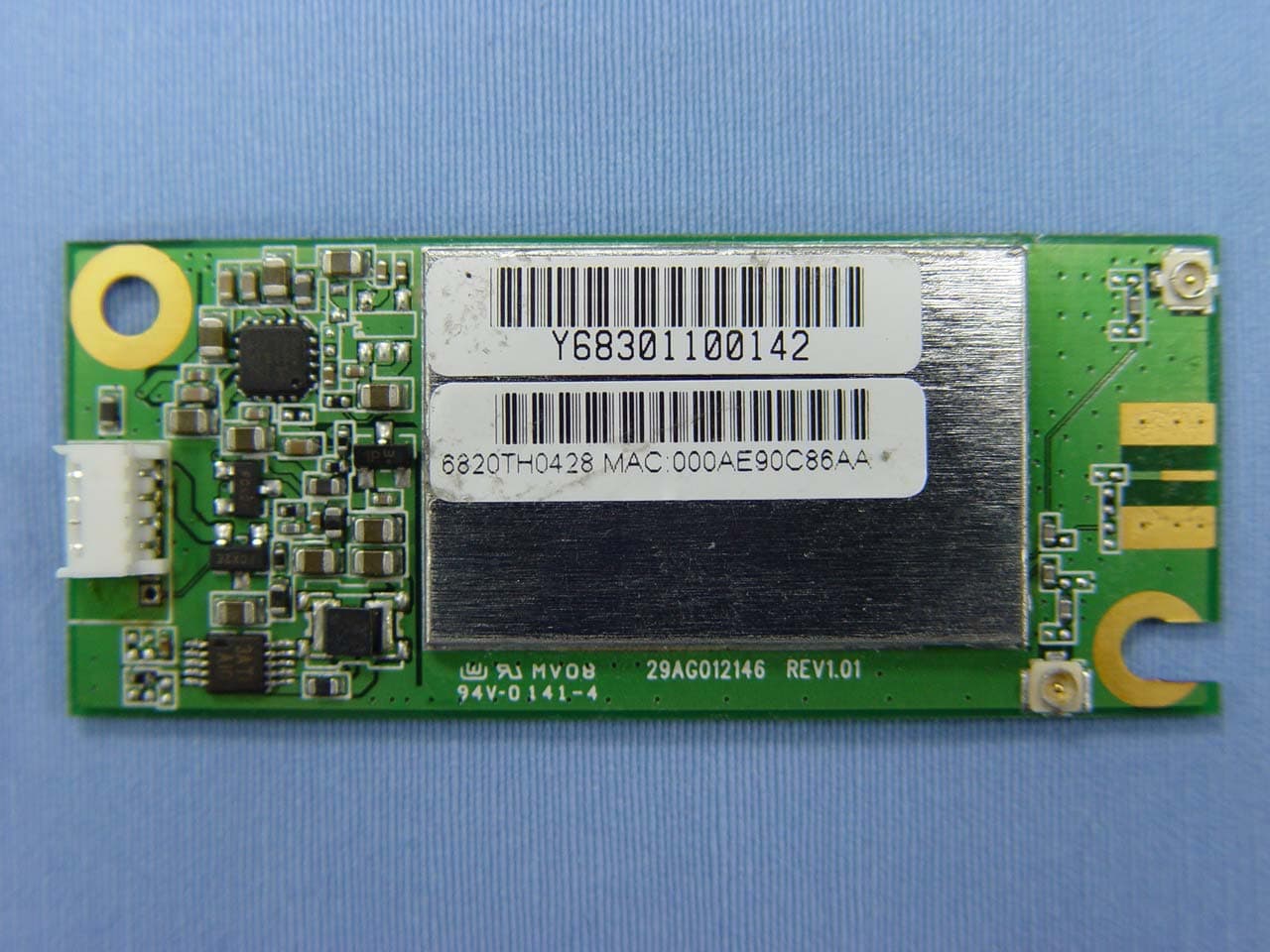
ROL-ASI47010000
Oct 03, 2004802.11 b/g USB Module
Equipment Class
DTS - Digital Transmission System
ROL-ASS21010000
Aug 12, 2004Wireless USB Dongle
Equipment Class
DTS - Digital Transmission System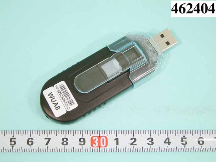
ROL-ASS21110128
Aug 09, 2004USB DONGLE
Equipment Class
DTS - Digital Transmission System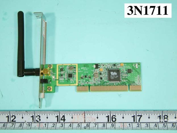
ROL-ASW2301
Jan 04, 2004ASTARTE / SOFTGATE
Equipment Class
DTS - Digital Transmission System
ROL-ASW2201
Dec 23, 2003ASTARTE/SOFTGATE
Equipment Class
DTS - Digital Transmission System