ROYCCR24RMOTWireless Microphone System - Base Receiver
Trinus Systems Inc.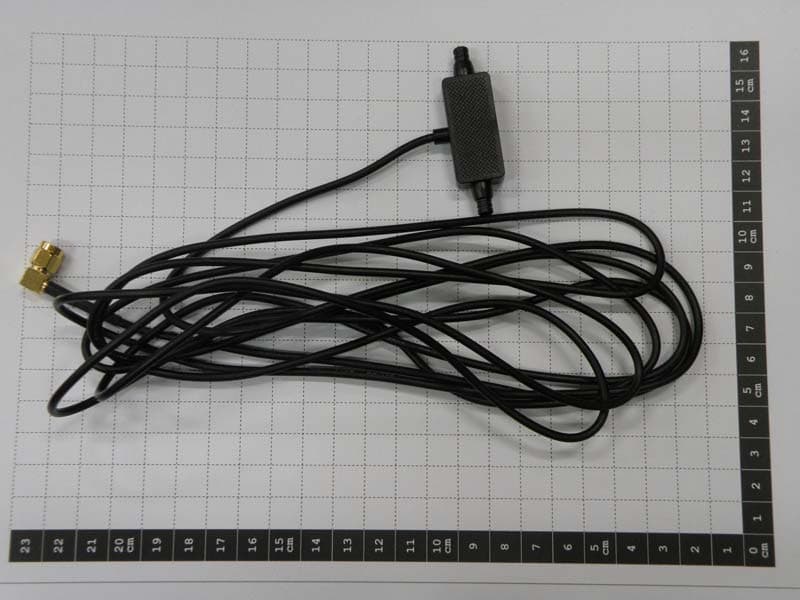
Click to zoom
Application Details
- Equipment Class
- DSS - Part 15 Spread Spectrum Transmitter
- Date of Grant
- Dec 21, 2010
- Application Purpose
- Original Equipment
- Date of Application
- Dec 21, 2010
- Equipment Note
- Wireless Microphone System - Base Receiver
- Frequency Range
- 2401.05600000 - 2482.27200000
- Company
- Trinus Systems Inc.
- Country
- South Korea
Documents & Files
Document Text
Text extracted from the exhibit documents filed with the FCC. Open a document above to read the original.
Users Manual
Wireless Microphone System User Guide 2Wireless Microphone System © 2010 MOTOROLA, INC. All rights reserved. Motorola reserves the right to make changes to any product to improve reliability, function, or design. Motorola does not assume any product liability arising out of, or in connection with, the application or use of any product, circuit, or application described herein. No license is granted, either expressly or by implication, estoppel, or otherwise under any patent right or patent, covering or relating to any combination, system, apparatus, machine, material, method, or process in which Motorola products might be used. An implied license exists only for equipment, circuits, and subsystems contained in Motorola products. MOTOROLA and the Stylized M Logo are registered trademarks of Motorola, Inc. Other product names mentioned in this manual may be trademarks or registered trademarks of their respective companies and are hereby acknowledged. © Motorola, Inc. 2010. April, 14, 2010 Support Motorola, Inc. 1301 E. Algonquin Road, Schaumburg, IL 60196 U.S.A. Inside the USA and Canada, call Motorola System Support Center at 1-800-221-7144. User Guide3 Safety and General Information Product Safety and RF Exposure for Electronic Devices with RF Transmit and Receive Capability Electronic devices - Where this term is specified, it refers to both the handheld/ body worn wireless microphone and the base. The microphone and base will be referred to individually where appropriate. RF Energy Exposure Awareness and Control Information and operational Instructions for General Population Use. Note: This electronic device is authorized for general population/consumer use. This electronic device uses electromagnetic energy in the radio frequency (RF) spectrum to provide communications between two or more users over a distance. It uses radio frequency (RF) energy or radio waves to send and receive data. RF energy is one form of electromagnetic energy. Other forms include, but are not limited to, sunlight and x-rays. RF energy, however, should not be confused with these other forms of electromagnetic energy, which when used improperly, can cause biological damage. Very high levels of x-rays, for example, can damage tissues and genetic material. Experts in science, engineering, medicine, health, and industry work with organizations to develop standards for safe exposure to RF energy. These standards provide recommended levels of RF exposure for both workers and the general public. These recommended RF exposure levels include substantial margins of protection. All Motorola electronic devices with transmit and receive capability are designed, manufactured, and tested to ensure they meet government-established RF exposure levels. In addition, manufacturers BEFORE USING THIS ELECTRONIC DEVICE, READ THIS BOOKLET WHICH CONTAINS IMPORTANT OPERATING INSTRUCTIONS FOR SAFE USAGE AND RF ENERGY AWARENESS AND CONTROL INFORMATION AND OPERATIONAL INSTRUCTIONS FOR COMPLIANCE WITH RF ENERGY EXPOSURE LIMITS IN APPLICABLE NATIONAL AND INTERNATIONAL STANDARDS. ALSO READ THE OPERATIONAL INSTRUCTIONS FOR SAFE USAGE. CAUTION 4Wireless Microphone System also recommend specific operating instructions to users of those electronic devices. These instructions are important because they inform users about RF energy exposure and provide simple procedures on how to control it. Please refer to the following websites for more information on what RF energy exposure is and how to control your exposure to assure compliance with established RF exposure limits: http://www.fcc.gov/oet/rfsafety/rf-faqs.html http://www.osha.gov/SLTC/radiofrequencyradiation/ index.html CCR24TMOT This device was evaluated for typical hand-held (held-to-face) operations with 2.5cm spacing from the front of the radio. For hand-held operation, the radio should be held 2.5cm from the user’s face in order to comply with FCC RF exposure requirements. (1g Head SAR: 0.088mW/g) For body worn operation, this tracker has been tested and meets the FCC RF exposure guidelines when used with the accessories supplied for this product.(1g Body SAR: 0.131mW/g) Use of other accessories may not ensure compliance with FCC RF exposure guidelines. CCR24RMOT This equipment complies with FCC radiation exposure limits set forth for an uncontrolled environment. This equipment should be installed and operated with minimum distance 20cm between the radiator & your body. This transmitter must not be co-located or operating in conjunction with any other antenna or transmitter. Federal Communication Commission (FCC) Regulations (US markets only) The FCC rules require manufacturers to comply with the FCC RF energy exposure limits for electronic devices with transmit and receive capability before they can be marketed in the U.S. When those electronic devices are used as a consequence of employment, the FCC requires users to be fully aware of and able to control their exposure to meet occupational requirements. Exposure awareness can be facilitated by the use of a User Guide5 product label directing users to specific user awareness information. Your Motorola electronic device has a RF Exposure Product Label. Do not remove this RF Exposure Label from the device. Also, your Motorola user manual, or separate safety booklet includes information and operating instructions required to control your RF exposure and to satisfy compliance requirements. Compliance with RF Exposure Standards Your Motorola electronic device is designed and tested to comply with a number of national and International standards and guidelines (listed below) for human exposure to radio frequency electromagnetic energy. This electronic device complies with the IEEE (FCC) and ICNIRP exposure limits for general population/uncontrolled RF exposure environments. Your Motorola electronic device complies with the following RF energy exposure standards and guidelines: • United States Federal Communications Commission, Code of Federal Re…
Text truncated - open the document above for the full version.
Cover Letter(s)
Trinus Systems,Inc. Unitech-Ville 8F 803, #1141-2 Beakseok-Dong, Ilsandong-Gu, Goyang City, Kyeonggi-Do, Korea 410-722 E-MAIL : [email protected] Federal Communications Commission Authorization and Evaluation Division Confidentiality Request regarding application for certification of FCC ID:ROYCCR24TMOT & ROYCCR24RMOT Pursuant to Sections 0.457 and 0.459 of the Commission’s Rules, we hereby request confidential treatment of information accompanying this application as outlined below: 1. Block Diagram 2. Schematic Diagram 3. Operational description The above material contains trade secrets or technical data, which would customarily be guarded from competitors. We do not want these documents to be accessible to the general public. The public disclosure of these materials may be harmful to the applicant and provide unjustified benefits to its competitors. The applicant understans that pursuant ot Section 0.457 of the Rules, disclosure of this application and all accompanying documentation will not be made before the date of the Grant for this application. Sincerely, Date : 02 th of Dec, 2010
Cover Letter(s)
Trinus Systems Inc Date 2 th of December , 2010 Compliance Certification Services Certification Division 561F Monterey Road Morgan Hill, CA 95037 To whom it may concern: We, the undersigned, hereby authorize Korea Testing Laboratory, to act on our behalf in all manners relating to application for equipment authorization, including signing of all documents relating to these matters. Any and all acts carried out by Korea Testing Laboratory on our behalf shall have the same effect as acts of our own. We, the undersigned, hereby certify that we are not subject to a denial of federal benefits, that includes FCC benefits, pursuant to Section 5301 of the Anti-Drug Abuse Act of 1988, 21 U.S.C. 853(a). In authorizing KTL as our agent, we still recognize that we are responsible to: a) comply with the relevant provisions of the certification program; b) make all necessary arrangements for the conduct of the evaluation, including provision for examining documentation and access to all areas, records (including internal audit reports) and personnel for the purposes of evaluation (e.g. testing, inspection, assessment, surveillance, reassessment) and resolution of complaints; c) make claims regarding certification only in respect of the scope for which certification has been granted; d) do not use our product certification in such a manner as to bring the Certification Division into disrepute and not make any statement regarding our product certification which the Certification Division may consider misleading or unauthorized; e) upon suspension or cancellation of certification, discontinue use of all advertising matter that contains any reference thereto and return any certification documents as required by the Certification Division; f) use certification only to indicate the products are certified as being in conformity with specified standards; g) endeavor to ensure that no certificate or report nor any part thereof is used in a misleading manner; h) ensure that any reference to our product certification in communication media such as documents, brochures or advertising, complies with the requirements of the Certification Division; i) keep a record of all complaints made known to the us relating to the product’s compliance with requirements of the relevant standard and to make these records available to the Certification Division when requested; j) take appropriate action with respect to such complaints and any deficiencies found in products or services that affect compliance with the requirements for certification; k) document the actions taken. This authorization is valid until further written notice from the applicant. Sincerely Yours, Signature Here REMARK: 1. This authorization letter will be sent along with your application when filing with the Certification Division. 2. Please follow the format and type it on company letterhead and send original to us.
Cover Letter(s)
Chris Harvey From: Sung-kyu Cho [[email protected]] Sent: Monday, December 20, 2010 6:20 AM To: [email protected] Cc: [email protected]; [email protected] Subject: RE: Trinus Systems Inc, FCC ID: ROYCCR24RMOT, Assessment NO.: AN10T1249, Notice#1 Attachments: Test setup photo_CCR24RMOT.pdf; Internal photo_CCR24RMOT.pdf; Circuit diagram_CCR24RMOT.pdf; Circuit description_CCR24RMOT.pdf; Antenna Spec_CCR24RMOT.pdf; Test_Report_CCR24RMOT_FCC15.247.pdf; Test_Report_CCR24TMOT_FCC15.247.pdf; MPE REPORT-CCR24RMOT.pdf Page 1 of 2RE: Trinus Systems Inc, FCC ID: ROYCCR24RMOT, Assessment NO.: AN10T1249, N ... 12/20/2010 Dear Chris, My answers are embeded below. This project is urgent so your fast review will be appreciated. -----Original Message----- From: [email protected] [mailto:charvey [email protected]] Sent: Friday, December 17, 2010 12:32 AM To: [email protected] Cc: [email protected]; [email protected] Subject: Trinus Systems Inc, FCC ID: ROYCCR24RMOT, Assessment NO.: AN10T1249, Notice#1 Receiver Dear SK Cho, You are listed as the Technical Contact for the above referenced TCB application. The following item(s) need(s) to be resolved before the review can be continued: 1. The Internal Photos do not seem to show the RF Circuitry and RF connection to the antenna connector. Please provide additional Internal Photos to show these RF areas. Ans) I've attached revised internal photo. 2. The Test Setup photo exhibit submitted is actually the setup of the Transmitter device. Please submit a Test Setup Photo exhibit for the Receiver unit (you can extract this from the RF Test report). Ans) I've attached test setup photo again. 3. The Schematic exhibit submitted in the Receiver application documents only the Transmitter. Please provide the Schematic exhibit for the Receiver. Ans) I've attached receiver schematic. 4. The Operational Description shows Channels 0-90, ending at 2478.816 MHz, but the test report goes to Channel 94, ending at 2482.272 MHz. Please confirm which is correct and update the exhibit(s) as needed. Ans) I've attached operatinoal description including revised frequency table. 5. FCC 15.203 requires that antennas that have an removable connector utilize a unique antenna connector (non-standard). Please provide the Antenna Specification exhibit for the antenna used with the Receiver device. Ans) The antenna connector type is reverse sma type. I've attached antenna spec. 6. The RF Exposure MPE exhibit states an antenna gain of 1.32dBi, but the RF Test report indicates 2.51 dBi antenna gain. Please confirm which antenna gain is correct and update the exhibit(s) as necessary. Ans) I've attahced revised MPE exhibit. 7. The Upper Side Band Edge Plot (page 14 of 35 of Transmitter RF Report) seems to show a center frequency of the fundamental located at approximately 2481.5MHz which seems to be lower than the band edge channel stated as 2482.272MHz. Ans) The center frequency was set to 2483.5 MHz. There's digit limitation so center frequency is displayed at 2483 MHz but actual center frequency was set to 2483.5 MHz. 8. The MPE Calculation states that the IC Limit is 10mW/cm2, but the limit should be 10W/m2, which is equivalent to 1mW/cm2, which is equivalent top the FCC MPE limit. Also, for a Mobile RF Exposure device the minimum separation distance is 20cm, so indicating or calculating a closer safe separation is inappropriate. Please correct this exhibit. Ans) I've attahced revised MPE exhibit. 9. The RF Report Section 1.2 lists the Antenna Gain as Ver 1.0 and the Function Type as Ver 1.0. Please correct these items. Ans) I corrected it. I've attached test report. The items indicated above must be submitted before processing can continue on the above referenced application. Failure to provide the requested information within 30 days of the original e-mail date may result in application dismissal and forfeiture of the filing fee. Also, please note that partial responses increase processing time and should not be submitted. Any questions about the content of this correspondence should be directed to the e-mail address listed below the name of the sender. Revised documentation should not be emailed, but instead should be submitted through "Add Attachment" function at the UL-CCS website. Please have your Assessment Number and FCC ID/IC Certification number handy. You may use the following link: https://cert.ccsemc.com/filing/ Best regards, Chris Harvey [email protected] No virus found in this message. Checked by AVG - www.avg.com Version: 10.0.1170 / Virus Database: 426/3326 - Release Date: 12/19/10 Page 2 of 2RE: Trinus Systems Inc, FCC ID: ROYCCR24RMOT, Assessment NO.: AN10T1249, N ... 12/20/2010
External Photos
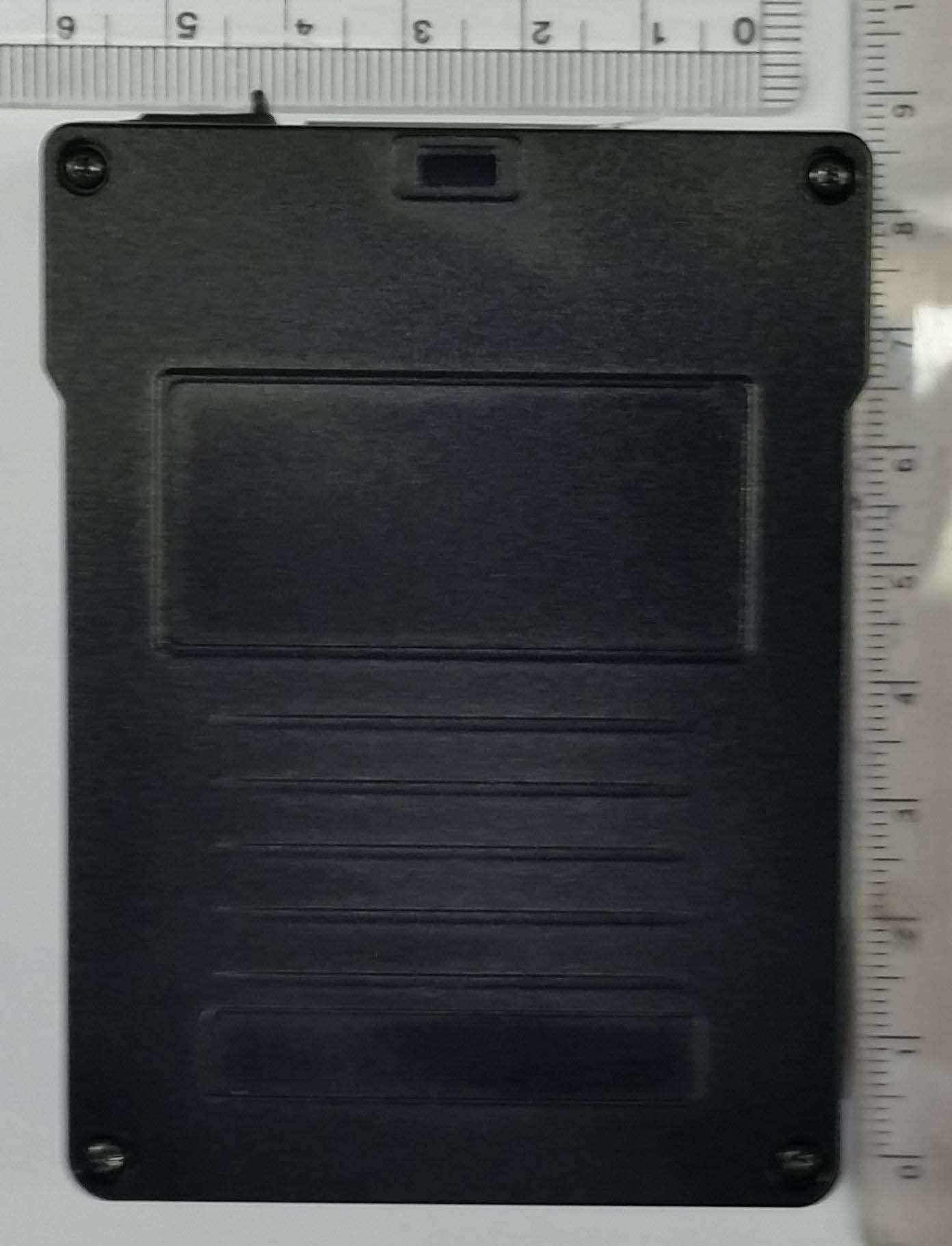
Model number : CCR24RMOT Photographs (Outside) Model number : CCR24RMOT Photographs (Outside) Model number : CCR24RMOT Photographs (Outside)
ID Label/Location Info
Model Number : CCR24RMOT Label Information Model Number : CCR24RMOT Label Information
Internal Photos
Model Number : CCR24RMOT Photographs (Inside) Model Number : CCR24RMOT Photographs (Inside) Model Number : CCR24RMOT Photographs (Inside) Model Number : CCR24RMOT Photographs (Inside)
Operational Description
1 승 승 인 인 원 원 H H P P - - 2 2 . . 4 4 N N - - R R X X T T ( ( G G L L A A S S S S ) ) REXTRON CO., LTD. DRAWN CHECKED APPROVED 김선군 이한수 최영 Approved by (주) TRINUS DRAWN CHECKED APPROVED 2010. 08 . 25 . 1. Specifications 2 1.1 General Standards 1.1.1 Model name : HP-2.4N-RXT(GLASS) 1.1.2 Antenna type : PCB antenna 1.2 Electrical Standards 1.2.1 Frequency range : 2.4~2.5GHz 1.2.2 V.S.W.R : 1.5 : 1(max) 1.2.3 Radiation pattern : Omni-directional 1.2.4 Polarization : Dipole type 1.2.5 Impedance : 50 1.3 Mechanical Standards 1.3.1 Base body : PC (Plastics-Component) 1.3.2 Color : Black 1.3.3 Cable ass’y : RG174 cable + SMA R/A connector (Reverse Fe-male) 1.3.7 Length : Antenna 56±1mm , Cable Ass’y 3 ft ± 5cm , 10ft ± 5cm 1.3.8 Thickness : 9.5±1 1.3.9 Operating temperature : -20°C ~ +50°C 2. Exterior 3 3. Test data sheet Parameter Specification Test Data V.S.W.R 1.5:1(max) 3 ft =1.2:1 10 ft =1.12:1 Return Loss -15 dB(max) 3 ft = -20 dB 10 ft = -24dB 4. Data sheet (안테나 측정 값) 5.1 Return Loss 3 ft 10 ft 5.2 VSWR 3 ft 10 ft 4 5.3 Smith Chart 3 ft 10 ft
RF Exposure Info
693, Haean-ro, Sangnok-gu, Ansan-si, Gyeonggi-do, KOREA (426-901) Tel. : +82-31-5000-133 http://www.ktl.re.kr Fax. : +82-31-5000-149 FP-204-03-01 RF EXPOSURE INFORMATION 1. EUT information Type of equipment Wireless Microphone System Device Category Mobile Device Model Name CCR24RMOT FCC ID ROYCCR24RMOT IC Number 5479A-CCR24RMOT Tx Frequency Band 2401.056 MHz ~ 2,482.272 MHz Antenna Gain 2.51 dBi 2. FCC MPE Limits The limit for Maximum Permissible Exposure (MPE), specified in FCC §1.1310, is listed in Table 1. According to FCC §1.1310: the criteria listed in the following table shall be used to evaluate the environmental impact of human exposure to radio-frequency(RF) radiation as specified in §1.1307(b). Table1. FCC LIMITS FOR MAXIMUM PERMISSIBLE EXPOSURE Frequency Range (MHz) Electric Field Strength (V/m) Magnetic Field Strength (A/m) Power Density (mW/cm 2 ) Average Time (Minutes) (A) Limits For Occupational / Control Exposures (f= frequency) 30-300 61.4 0.163 1.0 6 300-1500 ... ... ... 6 1500-100,000 ... ... ... 6 (B) Limits For General Population / Uncontrolled Exposure (f=frequency) 30-300 27.5 0.073 0.2 30 300-1500 ... ... f/1500 30 1500-100,000 ... ... 1.0 30 693, Haean-ro, Sangnok-gu, Ansan-si, Gyeonggi-do, KOREA (426-901) Tel. : +82-31-5000-133 http://www.ktl.re.kr Fax. : +82-31-5000-149 FP-204-03-01 3. IC MPE Limits The limit for Maximum Permissible Exposure (MPE), specified in IC RSS-102, is listed in Table 2. According to IC RSS-102: the criteria listed in the following table shall be used to evaluate the environmental impact of human exposure to radio-frequency(RF) radiation as specified in RSS-102 Table2. IC LIMITS FOR MAXIMUM PERMISSIBLE EXPOSURE (Uncontrolled Environment) Frequency Range (MHz) Electric Field (V/m rms) Magnetic Field (A/m rms) Power Density (W/m 2 ) Average Time (Minutes) 0.003-1 280 2.19 - 6 1-10 280/f 2.19/f - 6 10-30 28 2.19/f - 6 30-300 28 0.073 2 * 6 300-1500 1.585 f 0.5 0.0042 f 0.5 f/150 6 1500-15000 61.4 0.163 10 6 15000-150000 61.4 0.163 10 616000/f 1.2 150000-300000 0.158 f 0.5 4.21 x 10 -4 f 0.5 6.67 x 10 -5 f 616000/f 1.2 4. PROCEDURES The procedure used to determine the RF power density was based upon a calculation for determining compliance with the MPE requirements. This calculation is based on the highest EIRP possible from the system, considering maximum power and antenna gain, and considering the limit of uncontrolled exposure limit. The power density level is calculated at a distance of 20 cm. And Minimum distance is also calculated. MPE evaluations are calculated under Maximum Power condition in the band. Formula P d =PG / (4πr 2 ) Where, P d = Power Density (mW/cm 2 ) P= Power input to the antenna (in appropriate units, e.g., mW) G= Power gain of the antenna in the direction of interest relative to an isotropic radiator π=3.1416 r=distance between observation point and centre of the radiator (cm) 693, Haean-ro, Sangnok-gu, Ansan-si, Gyeonggi-do, KOREA (426-901) Tel. : +82-31-5000-133 http://www.ktl.re.kr Fax. : +82-31-5000-149 FP-204-03-01 5. Calculated MPE Result The power density limit for General Population/Uncontrolled Exposure at each frequency is determined based on the information in Table 1(FCC) & Table 2(IC). MPE evaluations are calculated under Maximum Power condition. Table3. Calculated MPE Data according to FCC/IC limit Frequency 2,482.272 MHz Limit 1 mW/cm 2 Distance (cm), R 20 cm ERP 24.88 dBm (307.6 mW) Ant. Gain, G 2.51 dBi Power Density (mW/cm 2 ) 0.109
Test Report
ATTESTATION STATEMENT This device (FCC ID : ROYCCR24TMOT & ROYCCR24RMOT ) complies with the following Part 15 regulations. 15.247(a)(1) • the hopping sequence must be pseudorandom • all channels are used equally on average • the receiver input bandwidth is approximately equal to the transmit bandwidth • the receiver hops in sequence with the transmitted signal 15.247(g) the system is designed to comply with all of the regulations in Section 15.247 when the transmitter is presented with a continuous data (or information) 15.247(h) the system does not coordinate its channel selection/hopping sequence with other frequency hopping systems for the express purpose of avoiding the simultaneous occupancy of individual hopping frequencies by multiple transmitters Sincerely Yours,
Test Report
Report No.: 10-2341-050-01 Page 1 of 35 Pages 693, Haean-ro, Sangnok-Gu, Ansan-si, Gyunggi-Do , Korea (426-901) Tel. : +82-31-5000-132 http://www.ktl.re.kr Fax. : +82-31-5000-149 FP-204-03-01 TEST REPORT 1. Applicant Name : Trinus Systmes Inc Address : Unitech-Ville 8F 803, #1141-2 Beakseok-Dong, Ilsandong-Gu, Goyang City, Gyeonggi-Do, Korea 410-722 2. Products Name : Wireless Microphone System Model/Type : CCR24RMOT FCC ID : ROYCCR24RMOT Manufacturer : Trinus Systmes Inc 3. Test Standard : FCC CFR 47 Part 15, Subpart C section 15.247 RSS-210 Issue 7 4. Test Method : ANSI C63.4-2009 5. Test Result : Positive 6. Date of Application : October. 06, 2010 7. Date of Issue : October. 22, 2010 Tested by Approved by ` Sung-kyu Cho Jeong-min Kim Telecommunication Team Engineer Telecommunication Team Manager The test results contained apply only to the test sample(s) supplied by the applicant, and this test report shall not be reproduced in full or in part without approval of the KTL in advance. Report No.: 10-2341-050-01 Page 2 of 35 Pages 693, Haean-ro, Sangnok-Gu, Ansan-si, Gyunggi-Do , Korea (426-901) Tel. : +82-31-5000-132 http://www.ktl.re.kr Fax. : +82-31-5000-149 FP-204-03-01 TABLE OF CONTENTS 1. GENERAL INFORMATIONS .................................................................................................. 4 1.1. Applicant (Client) .............................................................................................................................................. 4 1.2. Equipment (EUT) ............................................................................................................................................... 4 1.3. Testing Laboratory ............................................................................................................................................ 5 1.4. Channel Frequeny Table .................................................................................................................................. 5 2. SUMMARY OF TEST RESULTS ............................................................................................ 6 3. MEASUREMENT & RESULTS ............................................................................................... 7 3.1. 20 dB Bandwidth ............................................................................................................................................... 7 3.1.1. Test Setup Layout .................................................................................................................................... 7 3.1.2. Test Procedure ......................................................................................................................................... 7 3.1.3. Limits ........................................................................................................................................................ 7 3.1.4. Test result ................................................................................................................................................. 7 3.2. Maximum Peak Power .................................................................................................................................... 10 3.2.1. Test Setup Layout .................................................................................................................................. 10 3.2.2. Test Procedure ....................................................................................................................................... 10 3.2.3. Limits ...................................................................................................................................................... 10 3.2.4. Test result ............................................................................................................................................... 10 3.3. 100 KHz Bandwidth of Frequency Band Edges ........................................................................................... 13 3.3.1. Test Setup Layout .................................................................................................................................. 13 3.3.2. Test Procedure ....................................................................................................................................... 13 3.3.3. Limits ...................................................................................................................................................... 13 3.3.4. Test result ............................................................................................................................................... 13 3.4. Hopping Channel Separation ......................................................................................................................... 15 3.4.1. Test Setup Layout .................................................................................................................................. 15 3.4.2. Test Procedure ....................................................................................................................................... 15 3.4.3. Limits ...................................................................................................................................................... 15 3.4.4. Test result ............................................................................................................................................... 15 Report No.: 10-2341-050-01 Page 3 of 35 Pages 693, Haean-ro, Sangnok-Gu, Ansan-si, Gyunggi-Do , Korea (426-901) Tel. : +82-31-5000-132 http://www.ktl.re.kr Fax. : +82-31-5000-149 FP-204-03-01 3.5. Number of Hopping Channels ....................................................................................................................... 17 3.5.1. Test Setup Layout .................................................................................................................................. 17 3.5…
Text truncated - open the document above for the full version.
Test Setup Photos
Model Number : CCR24RMOT Test setup Photo
Contact Information
Applicant
Ahnse Lee(Director of R & D Center)
Test Firm
Korea Testing LaboratoryYang-hyun Kim
Technical Specifications
| # | Rule Parts | Frequency Range | Power Output |
|---|---|---|---|
| 1 | 15C | 2.40 GHz - 2.48 GHz | 307.00 mW |
Other Applications from Trinus Systems Inc.
ROYSA366PBWC
Aug 18, 2015Body Worn Camera System
Equipment Class
DTS - Digital Transmission System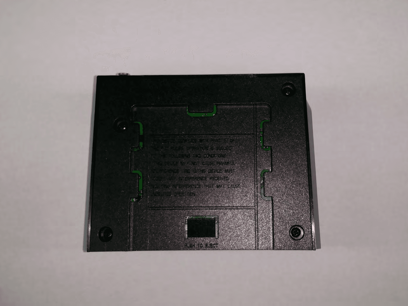
ROY3102PNARE
Apr 28, 2014Wireless Transceiver System
Equipment Class
DSS - Part 15 Spread Spectrum Transmitter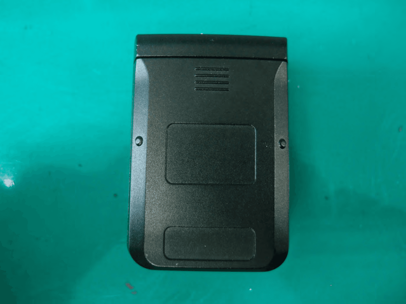
ROY3101PNATR
Apr 28, 2014Wireless Transceiver System
Equipment Class
DSS - Part 15 Spread Spectrum Transmitter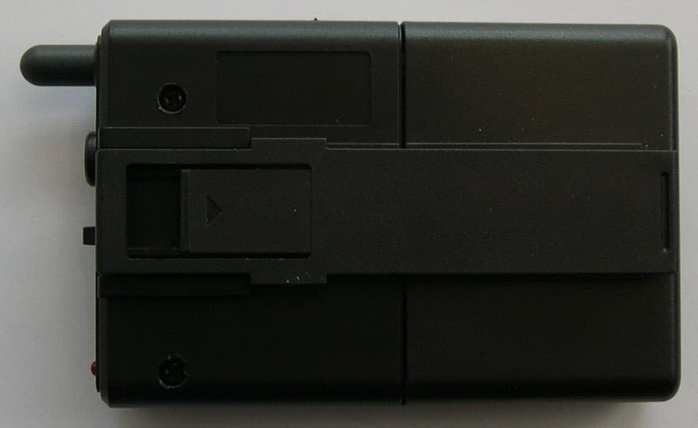
ROYTPRF-900H
Dec 15, 2003Wireless Transceiver System, Handset
Equipment Class
DXX - Part 15 Low Power Communication Device Transmitter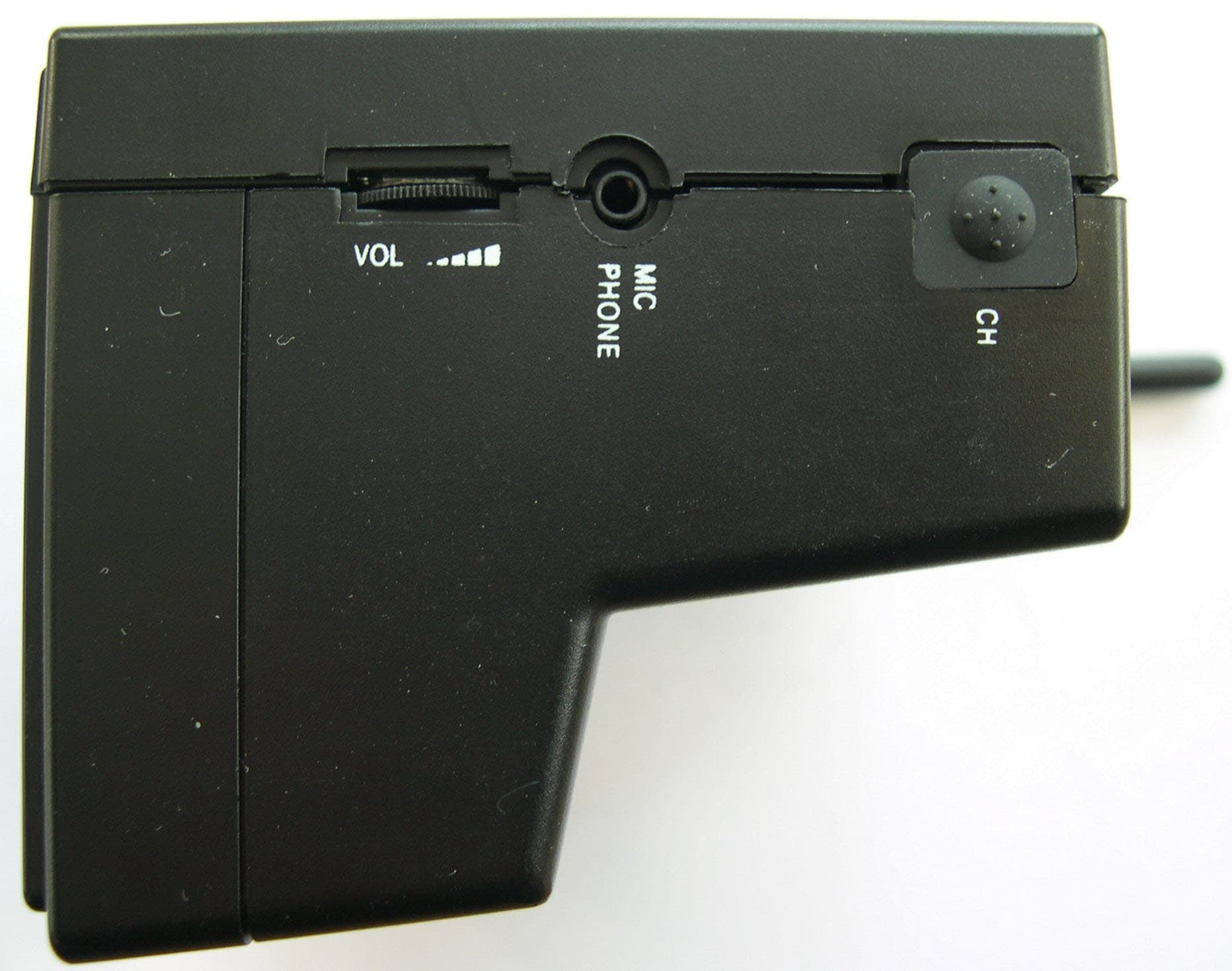
ROYTPRF-900B
Dec 15, 2003Wireless Transceiver System, Base Station
Equipment Class
DXX - Part 15 Low Power Communication Device Transmitter