ROYTPRF-900HWireless Transceiver System, Handset
Trinus Systems Inc.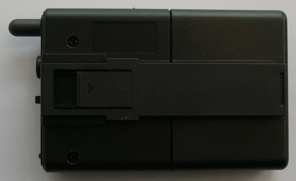
Click to zoom
Application Details
- Equipment Class
- DXX - Part 15 Low Power Communication Device Transmitter
- Date of Grant
- Dec 15, 2003
- Application Purpose
- Original Equipment
- Date of Application
- Dec 15, 2003
- Equipment Note
- Wireless Transceiver System, Handset
- Frequency Range
- 925.30000000 - 927.25000000
- Company
- Trinus Systems Inc.
- Country
- South Korea
Documents & Files
Document Text
Text extracted from the exhibit documents filed with the FCC. Open a document above to read the original.
Users Manual
Wireless Transceiver System (TPRF-900) Manual 1. Getting Started . Introduction: This equipment has been manufactured and tested under strict quality control conditions. This Wireless Transceiver System has been tested within a 1000 feet radius. The receiving chips use a Super Heterodyne method, while the Base and Hand sets use and coincides with a Digital Coded method. In case of frequencies overlapping with other waves, up to 40 different channels can be selected for clearer reception by manually using the Channel Switch button . Equipments: a. Base Set – 1 unit b. Hand Set – 1 unit c. Headset (optional) – 2 units d. Microphone – 1 unit e. Rechargeable Battery – 1 pack f. User’s Manual - 1 book * Accessories parts are subject to change without any notice for functional improvements. . Cautions: a. Use only the given antenna with the Base Set b. Do not immerse in water or keep in humid areas c. Do not place near TV, speakers, or other electronic devices d. Before installation, check power supply and voltage to avoid hazards e. Do not apply force or shock to the unit f. Do not disassemble the unit . Parts Description: Base Set: Hand Set: 2. Functions: This Wireless Transceiver System can automatically search, find, and memorize the best reception within 40 channels. Therefore, top of the line clarity and communication is guaranteed. a. Hand Set: The Talk ON/OFF switch, can activate the Base unit. b. Base Set: The RJ-45 #6 pin is used for controlling the communication. If a LOW (TTL:”L”) signal is received, the communication is enabled regardless the Hand Set is ON or OFF. If a HIGH (TTL:"L") signal is received, the communication is disconnected. c. Channel Surfing: If reception becomes unclear, press the Channel Switch button once. d. Security: The CPU and EEPROM can choose from one million different passwords to prevent eavesdropping. e. Paging: The Base Set can page the Hand Set for communication. f. Standby: While charging, the Hand Set is in standby mode. g. Communication Range: When the Hand Set goes out of range, a warning beep will sound on the Hand Set. h. Low Battery: When the Hand Set is low on battery, a warning beep will sound and a warning light will appear. 3. Base and Hand Set Installation Base Set a. Connect the RJ-45 connector to the Base Set b. Connect the Microphone (optional Headset) to the Base Set Hand Set a. The battery pack is not built-in the Hand Set for safety reasons. Connect the battery pack to the Hand Set and then turn the power switch ON (located in the battery storage area) b. Prior to use, charge the unit by placing the Hand Set in the Base Set for at least 3~5 hours c. Connect the Microphone (optional Headset) to the Hand Set RJ-45 Connector Pin Description ① VCC : DC power (10V ~ 16V DC) ② GND : DC power GND ③ RX Audio : RX Audio signal + TX Audio signal ④ GND : ⑤ TX Audio(AUX) : TX Audio ⑥ RF module ON : (TTL : “L”) ⑦ RF Loop ON : Hand, Base Set Loop ON signal (TTL : “L”) ⑧ MIC/Headset ON : MIC/Headset ON signal (TTL : “L”) Beep Tone Power ON/OFF---------------------------Æ Beep Low Battery ----------------------------Æ Bee- Beep Connection Established --------------------Æ Beep~ Hand and Base Set Recognition --------------Æ Beep~ Charging Mode ---------------------------Æ Beep~ Paging from Base Set----------------------Æ Beep~ Beep ~ Beep (continuously) Out of Communication Range-----------------Æ Bee-Bee-Beep Disconnection----------------------------Æ Beep 4. Rechargeable Battery Pack It is recommended that before using, charge the unit by placing the Hand Set in the Base Set for at least 3~5 hours. Replacing the Battery Pack a. Remove the battery cover on the Hand Set b. Turn the power switch OFF (located in the battery storage area) c. Detach the battery pack cable from Hand Set d. Connect the new battery pack to the Hand Set and then turn the power switch ON (located in the battery storage area) e. Close the battery cover 5. Recommendations a. Prior to use, charge the unit by placing the Hand Set in the Base Set for at least 3~5 hours b. The LED on the Base Set indicates Charging Mode. If LED light does not turn on, call the A/S center c. If the Hand Set is not in use for long periods, turn the power switch OFF (located in the battery storage area). d. Check the LED on Hand Set for Low Battery status e. Charge Hand Set when not in use for short periods 6. Troubleshooting Problems Check Points No reception - check the battery status - check the connection and cables - check the communication range Poor reception, static, noise - change the location of Base Set - check the communication range - check to see if placed near TV, speakers, or other electronic devices FCC COMPLIANCE STATEMENT THIS DEVICE COMPLIES WITH PART 15 OF THE FCC RULES. Operation is subject to the following two conditions; (1) this device may no t cause harmful interference, and (2) this device must accept any interferenc e received, including interference that may cause undesired operation. CAUTION: 1) Changes or modifications not expressly approved by the party responsible fo r compliance could void the user’s authority to operate the equipment. 2) This device and its antenna must not be co-located or operating in conjunction with an y other antenna or transmitter.
External Photos
SK TECH CO., LTD. Page 1 of 2 SKT SKTTRT-031215-009 FCC ID: ROYTPRF-900H External Photographs of EUT <Photograph 1: HANDSET - Front View> <Photograph 2: HANDSET - Rear View> SK TECH CO., LTD. Page 2 of 2 SKT SKTTRT-031215-009 FCC ID: ROYTPRF-900H <Photograph 3: HANDSET - Top View> <Photograph 4: HANDSET - Bottom View> <Photograph 5: HANDSET – Left Side View>
ID Label/Location Info
SK TECH CO., LTD. Page 1 of 1 SKT SKTTRT-031215-009 FCC ID: ROYTPRF-900H FCC ID Label Location & Sample << HANDSET >> Label is attached on the rear panel of the HANDSET The label shall be permanently affixed at the conspicuous location on the device and be readily visible to the user at the time of purchase. 25mm LABEL LOCATION COMPLIANCE STATEMENT LOCATION WIRELESS TRANCEIVER SYSTEM Model: TPRF-900H Manufacturer: Trinus System Inc. FCC ID: ROYTPRF-900H This device complies with Part 15 of the FCC rules Operation is subject to the following two conditions; (1) This device may not cause harmful interference, and (2) This device must accept any interference received, including interference that may cause undesired operation. LABEL SAMPLE 12mm
Internal Photos
SK TECH CO., LTD. Page 1 of 4 SKT SKTTRT-031215-009 FCC ID: ROYTPRF-900H Internal Photographs of EUT <Photograph 1: HANDSET - Cover removed> SK TECH CO., LTD. Page 2 of 4 SKT SKTTRT-031215-009 FCC ID: ROYTPRF-900H <Photograph 2: HANDSET - Front View > SK TECH CO., LTD. Page 3 of 4 SKT SKTTRT-031215-009 FCC ID: ROYTPRF-900H <Photograph 3: HANDSET, RF module shielding cover removed > SK TECH CO., LTD. Page 4 of 4 SKT SKTTRT-031215-009 FCC ID: ROYTPRF-900H <Photograph 4: HANDSET - Rear View >
Operational Description
MAIN SYSTEMS with some Peripherals MAIN SYSTEM (Mobile Video System including VCR) is installed in the trunk of the cars. MAIN SYSTEM Placing HANDSET into the BASE 12VDC battery powered Mobile Video System including VCR 12VDC battery powered RED Color: BATT+ BLACK Color: GND WHITE Color: ACC ACC is in the state of the key in the car turned right Other Peripherals such as RADAR BASE powered through RJ45 Connector, HANDSET can be charged by placing it into BASE To 12VDC Battery To Peripherals (Camera & Controller) To BASE (RJ45) To Other Peripherals (RADAR, CABIN)
Operational Description
SK TECH CO., LTD. Page 1 of 1 SKT SKTTRT-031215-009 FCC ID: ROYTPRF-900H Operational Description (RF part) The HANDSET and BASE have the different RF modules, RU0926H18HKB and RU0902B18HKB respectively, which is a short –range, full duplex wireless radio transceiver. See the attached block diagrams and schematics. RX Audio/DATA Part Audio signals, which are received and demodulated in the RF module, are expended by Compander IC (KA8507D) and then adjusted by variable resistor (SVR2). The adjusted audio signals are amplified, and transmitted to Earphone. DATA, which are received and demodulated in the RF module, are amplified via transistors, TR8 & TR1, and then transmitted to RX DATA port on the Microprocessor (KS57P01504), which has 4K-byte one-time-programmable ROM. TX Audio/DATA Part Audio signals, which are input by MIC, are compressed by Compander IC and then adjusted by SVR1. The adjusted audio signals are modulated in the RF module. TX DATA, which are controlled by the Microprocessor, are directly modulated and radiated. EEPROM & RESET circuit EEPROM is used for storage of the identification code. As Power-ON-Reset functions, this circuit is activated in LOW. LOW battery indicator circuit (HANDSET) Where the voltage of the battery is below 3.1 V, the LOW battery indicated circuit is activated by IC K1A7031F and the LOWDET terminal of the Microprocessor. ANTENNA The antenna is affixed on it and no external ground is required or used with HANDSET.
Test Report
SK TECH CO., LTD. Page 1 of 11 SKT SKTTRT-031215-009 FCC ID: ROYTPRF-900H Certificate of Compliance Test Report No.: SKTTRT-031215-009 NVLAP CODE: 200220-0 Applicant: Trinus Systems Inc. Applicant Address: 310-3, ShinCheon-4Dong, Dong-Gu, Daegu, Korea 701-024 Device Under Test: Wireless Transceiver System FCC ID: ROYTPRF-900H Model No.: TPRF-900H Receipt No.: SKTEU03-0682 Date of receipt: December 3, 2003 Date of Issue: December 15, 2003 Location of Testing: SK TECH CO., LTD. 820-2, Wolmoon-Ri, Wabu-Up, Namyangju-Si, Kyunggi-Do, Korea Test Procedure: ANSI C63.4 / 2001 Test Specification: FCC Title 47, Part 15 Subpart C / August 26, 2003 Equipment Class: Part 15 Low Power Communication Device Transmitter Test Result: The above-mentioned device has been tested and passed.- Tested & Reported by: Jong-Soo, Yoon 12/15/2003 Approved by: Jae-Kyung, Bae 12/15/2003 Signature Date Signature Date Other Aspects: Abbreviations: · OK, Pass = passed · Fail = failed · N/A = not applicable ☞ •This test report is not permitted to copy partly without our permission. •This test result is dependent on only equipment to be used. •This test result is based on a single evaluation of one sample of the above mentioned. •This test report must not be used to claim product endorsement by NVLAP or any agency of the U.S Government. • We certify that this test report has been based on the measurement standards that is traceable to the national or International standards. NVLAP Lab. Code: 200220-0 SK TECH CO., LTD. Page 2 of 11 SKT SKTTRT-031215-009 FCC ID: ROYTPRF-900H >> CONTENTS << 1. GENERAL ............................................................................................... 3 2. TEST SITE .............................................................................................. 3 2.1 Location ................................................................................................3 2.2 List of Test and Measurement Instruments ...............................................4 2.3 Test Date ...............................................................................................4 2.4 Test Environment ...................................................................................4 3. DESCRIPTION OF THE EQUIPMENT UNDER TEST ................................. 5 3.1 Rating and Physical Characteristics ..........................................................5 3.2 Equipment Modifications .........................................................................5 3.3 Submitted Documents ............................................................................5 4. MEASUREMENT CONDITIONS ............................................................... 6 4.1 Description of test configuration ..............................................................6 4.2 List of Peripherals ...................................................................................6 4.3 Type of used Cables ...............................................................................6 4.4 Uncertainty ............................................................................................6 5. TEST AND MEASUREMENTS ................................................................... 7 5.1 ANTENNA REQUIREMENT ............................................................... 7 5.1.1 Regulation .......................................................................................7 5.1.2 Result .............................................................................................7 5.2 RADIATED EMISSIONS ................................................................... 8 5.2.1 Regulation .......................................................................................8 5.2.2 Test Procedure .................................................................................8 5.2.3 Test Results .....................................................................................9 Table 1: Open Field Radiated Emissions (HANDSET) ......................................... 9 5.3 OCCUPIED BANDWIDTH (BAND EDGE) ........................................ 10 5.3.1 Regulation .....................................................................................10 5.3.2 Test Procedure ...............................................................................10 5.3.3 Test Results ...................................................................................10 Table 2: Measured values of the Occupied bandwidth ..................................... 10 Figure 1: Plot of the Occupied Bandwidth (HANDSET, Operating at 925.30 MHz) 11 Figure 2: Plot of the Occupied Bandwidth (HANDSET, Operating at 927.25 MHz) 11 SK TECH CO., LTD. Page 3 of 11 SKT SKTTRT-031215-009 FCC ID: ROYTPRF-900H 1. GENERAL These tests were performed using the test procedure outlined in ANSI C63.4, 2001 for intentional radiators, and in accordance with the limits set forth in FCC Part 15.249 for Low Power Communication Device Transmitter. The EUT (Equipment Under Test) has been shown to be capable of compliance with the applicable technical standards. We attest to the accuracy of data. All measurements reported herein were performed by SK Tech Co., Ltd. and were made under Chief Engineer’s supervision. We assume full responsibility for the completeness of these measurements and vouch for the qualifications of all persons taking them. 2. TEST SITE SK TECH Co., Ltd. 2.1 Location 820-2, Wolmoon Ri, Wabu-Up, Namyangju-Si, Kyunggi-Do, Korea This test site is in compliance with ISO/IEC 17025 for general requirements for the competence of testing and calibration laboratories. This laboratory is accredited by NVLAP for NVLAP Lab. Code: 200220-0 and DATech for DAR-Registration No.: TTI-P-G155/97-10 SK TECH CO., LTD. Page 4 of 11 SKT SKTTRT-031215-009 FCC ID: ROYTPRF-900H 2.2 List of Test and Measurement Instruments Equipment Type Manufacturer Model No. Serial No. Cal. Due Date EMI Test Receiver Rohde&SchwarzESVS 10 825120/013 10, 2004 EMI Test Receiver Rohde&…
Text truncated - open the document above for the full version.
Test Setup Photos
SK TECH CO., LTD. Page 1 of 2 SKT SKTTRT-031215-009 FCC ID: ROYTPRF-900H Test set up photos <Radiated Emissions – HANDSET: Front View> SK TECH CO., LTD. Page 2 of 2 SKT SKTTRT-031215-009 FCC ID: ROYTPRF-900H <Radiated Emissions – HANDSET: Rear View>
Contact Information
Applicant
Ahnse Lee(Director of R & D Center)
Test Firm
SK Tech Co., Ltd.Jae-Yeong Hyun
Technical Specifications
| # | Rule Parts | Frequency Range | Power Output |
|---|---|---|---|
| 1 | 15C | 925.3 MHz - 927.25 MHz | - |
Other Applications from Trinus Systems Inc.
ROYSA366PBWC
Aug 18, 2015Body Worn Camera System
Equipment Class
DTS - Digital Transmission System
ROY3102PNARE
Apr 28, 2014Wireless Transceiver System
Equipment Class
DSS - Part 15 Spread Spectrum Transmitter
ROY3101PNATR
Apr 28, 2014Wireless Transceiver System
Equipment Class
DSS - Part 15 Spread Spectrum Transmitter
ROYCCR24RMOT
Dec 21, 2010Wireless Microphone System - Base Receiver
Equipment Class
DSS - Part 15 Spread Spectrum Transmitter
ROYTPRF-900B
Dec 15, 2003Wireless Transceiver System, Base Station
Equipment Class
DXX - Part 15 Low Power Communication Device Transmitter