ROYSA366PBWCBody Worn Camera System
Trinus Systems Inc.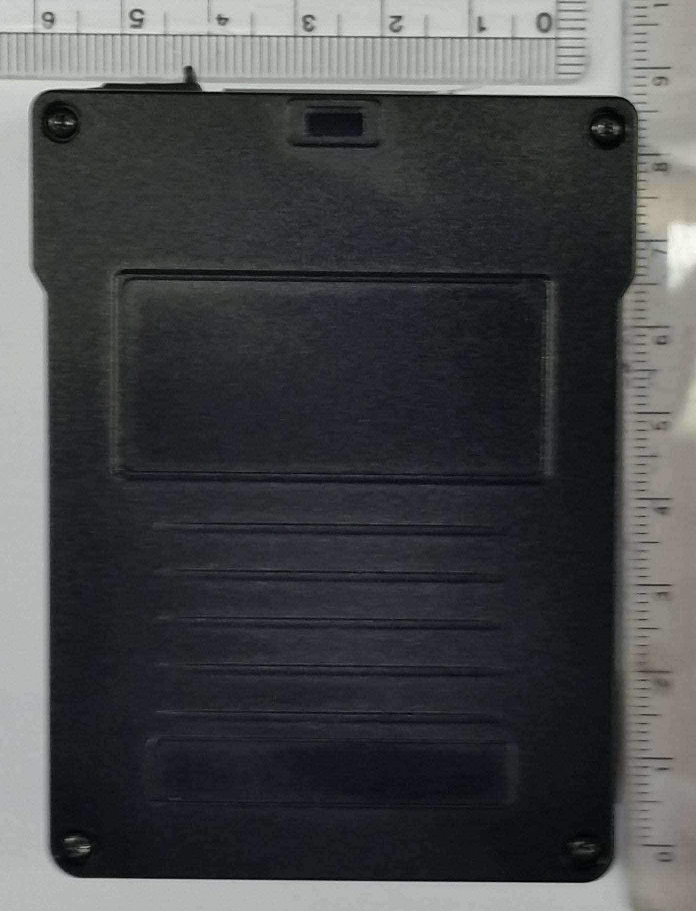
Click to zoom
Application Details
- Equipment Class
- DTS - Digital Transmission System
- Date of Grant
- Aug 18, 2015
- Application Purpose
- Original Equipment
- Date of Application
- Aug 18, 2015
- Equipment Note
- Body Worn Camera System
- Frequency Range
- 2412.00000000 - 2462.00000000
- Company
- Trinus Systems Inc.
- Country
- South Korea
Documents & Files
Document Text
Text extracted from the exhibit documents filed with the FCC. Open a document above to read the original.
Users Manual
--------------------------------------------------------------------------------------- Read this user guide carefully for safe operation and proper use of the product. Features and specifications are subject to change without notification. Arbitrator Body Worn Camera System ARB-SA366 User Guide FCC RF Radiation Exposure Statement This equipment complies with FCC RF radiation exposure limits set forth for an uncontrolled environment. This equipment should be installed and operated with a minimum distance of 5 millimeters between the radiator and your body. This transmitter must not be co-located or operated in conjunction with any other antenna or transmitter. Version 1.00 FCC ID : ROYSA366PBWC This device complies with part 15 of the FCC Rules. Operation is subject to The following two conditions : (1) This device may not cause harmful interference, and (2) this device must accept any interference received, including interference that may cause undesired operation. Caution: Any changes or modifications in construction of this device which are not expressly approved by the party responsible for compliance could void the user’s authority to operate the equipment. Note: This equipment has been tested and found to comply with the limits for a class B digital device, pursuant to part 15 of the FCC Rules. These limits are designed to provide reasonable protection against harmful interference in a residential installation this equipment generates, uses and can radiate radio frequency energy and, if not installed and used in accordance with the instructions, may cause harmful interference to radio communications, However, there is no guarantee that interference will not occur in a particular installation. If this equipment does cause harmful interference to radio or television reception, which can be determined by turning the equipment off and on, the user is encouraged to try to correct the interference by one or more of the following measures : -Reorient or relocate the receiving antenna. -Increase the separation between the equipment and receiver. -Connect the equipment into an outlet on a circuit different from that to which the receiver is connected. -Consult the dealer or an experienced radio / TV technician for help. CAUTION 1 18 AUDIT LOG INFORMATION-2 1. When Using the Battery Danger (1) Misusing the battery may cause the battery to get hot, explode, or ignite and cause serious injury. Be sure to follow the safety rules listed below: - Do not place the battery in fire or heat the battery. - Do not install the battery backwards so that the polarity is reversed. - Do not connect the positive terminal and the negative terminal of the battery to each other with any metal object (such as a wire). - Do not carry or store the batteries together with necklaces, hairpins, or other metal objects. - Do not pierce the battery with nails, strike the battery with a hammer, step on the battery, or otherwise subject it to strong impacts or shocks. - Do not solder directly onto the battery. - Do not expose the battery to water or salt water, or allow the battery to get wet. (2) Do not disassemble or modify the battery. The battery contains safety and protection devices which, if damaged, may cause the battery to generate heat, explode or ignite. (3) Do not place the battery on or near fire, stoves, or other high temperature locations. Do not place the battery in direct sunlight, use or store the battery inside cars in hot weather. Doing so may cause the battery to generate heat, explode, or ignite. Using the battery in this manner may also result in a loss of performance and a shortened life expectancy. (4) Do not insert the battery into equipment designed to be hermetically sealed. In some cases hydrogen or oxygen may be discharged from the cell which may result in rupture, fire or explosion. CAUTION : Risk of explosion if battery is replaced by an incorrect type. Dispose of used batteries according to the instructions. (Please refer to instruction for safe disposal of lithium polymer battery at page#3) Category Log Item Parameter System Power on/off System reboot by [event] [event] : a factor of reboot System Start [Product Name] [Firmware Version] [Serial#] Standby Start / End Configuration is changed Configuration error [file.setting] Log in/out [officer ID] [officer ID] Restoring FAT Start Restoring FAT End [with Error] SD formatted [with Error] Factory default Upgrading/Downgrading Start [Firmware File Name] [Firmware Version] Upgrading/Downgrading End [with Error] GPS Enabled / Disabled Time adjustment [Before] [After] [Before] = UTC time before adjustment [After] = UTC time after adjustment 17 2 CAUTION Warning (1)Immediately discontinue use of the battery if, while using, charging, or storing the battery, the battery emits an unusual smell, feels hot, changes color, changes shape or appears abnormal in any other way. Contact your authorized reseller or Panasonic if any of these problems are observed. (2) Do not place the batteries in microwave ovens, high-pressure containers, or on induction cookware. (3) In the event that the battery leaks and the fluid gets into one’s eye, do not rub the eye. Rinse well with water and immediately seek medical care. If left untreated the battery fluid could cause damage to the eye. Caution (1) If the device is to be used by small children, an adult should explain the contents of the user’s manual to the children. The person should provide adequate supervision to insure that the device is being used as explained in the user’s manual. (2) When the battery is worn out, insulate the terminals with adhesive tape or similar materials before disposal. Danger Be sure to follow the rules listed below while charging the battery. Failure to do so may cause the battery to become hot, explode, or ignite and cause serious injury. · When charging the battery, either use a specified battery charger or otherwise insure that the battery charging conditions specified by Panason…
Text truncated - open the document above for the full version.
Attestation Statements
ESTECH Co., Ltd. Head Office : Suite 1015 World Meridian II, 123 Gasan Digital 2-ro, Geumcheon-gu, Seoul 153-759, R. O. Korea * Tel : 822-867-3201, * Fax : 822-867-3204 Wep Site : http://www.estech.co.kr EMC Test Lab : 347-69, Jungbu-daero 147beon-gil, Majang-myeon, Icheon-si, Gyeonggi-do 467-811, R. O. Korea * Tel : 82-31-631-8037, * Fax : 82-31-631-8039 Declaration of Compliance 8F, RM801, UNITECHVILLE ILSAN-RO 142, ILSANDONG-GU, Date of issue : 14. Aug. 2015 GOYANG-SI, GYEONGGI-DO, SOUTH KOREA Zip Code : 410-722 Test Report No.:ESTF151508-003 Test Site : Estech Lab Attn : Ahnse Lee FCC IDENTIFIER : Declaration of Conformity APPLICANT : Trinus Systems Inc. FCC Rule Part(s) : Part 15B Equipment Class : Class B EUT Type : Body Worn Camera System Model Name : ARB-SA366 This device has been shown to be capable of compliance with the applicable technical standards as indicated in the measurement report and was tested in accordance with the measurement procedures specified in ANSI C63.4(2009). I attest to the accuracy of data and all measurements reported herein were performed by me or were made under my supervision and are correct to the best of my knowledge and belief. I assume full responsibility for the completeness of these measurements and vouch for the qualification of all persons taking there. Estech certifies that no party to this application has been denied the FCC benefits pursuant to Section 53C1 of the Anti-Drug Abuse Act of : 988, 21 U.S.C. 853(a) Jinmo. Yang Engineering Manager
Cover Letter(s)
SCS-F18: Project and Product Certification Representative Authorization Letter Page 2 of 3 Rev 5.0 Trinus Systems Inc. Aug.13.2015 To: SIEMIC, INC. 775 Montague Expressway, Milpitas, CA 95035 USA Dear Sir/Madam, Re: Product Certification Representative Authorization Letter We, Trinus Systems Inc. hereby authorize SIEMIC, Inc. to act as a Certification Body for certifying for the following project(s): (Product description : Body Worn Camera System , model name : ARB-SA366) FCC ID: ROYSA366PBWC Sincerely, Client’s signature : Client’s name / title : Ahnse Lee / Director of R&D Center Contact information / address : 8F, RM801, UNITECHVILLE ILSAN-RO 142, ILSANDONG-GU, GOYANG-SI , GYEONGGI-DO , South Korea , 410-722
Cover Letter(s)
SCS-F19: Confidentiality Request Letter Page 2 of 2 Rev 4.0 Trinus Systems Inc. Aug.13.2015 To: Federal Communications Commission Authorization and Evaluation Division 7435 Oakland Mills Road Columbia, MD Subject: Permanent Confidentiality Request for FCC ID: ROYSA366PBWC We hereby request confidential treatment of information accompanying this application as outlined below: - Block Diagram - Schematics - Operational Description The above materials contain trade secrets and proprietary information not customarily released to the public. The public disclosure of these materials may be harmful to the applicant and provide unjustified benefits to its competitors. The applicant understands that pursuant to Section 0.457 & 0.459 of the Rules, disclosure of this application and all accompanying documentation will not be made before the date of the Grant for this application. Sincerely, Client’s signature : Client’s name & title : : Ahnse Lee / Director of R&D Center Contact information / address: 8F, RM801, UNITECHVILLE ILSAN-RO 142, ILSANDONG-GU, GOYANG-SI , GYEONGGI-DO , South Korea , 410-722
Cover Letter(s)
Trinus Systems Inc. WIFI Channel 12 & 13 Declaration Letter To whom it may concern : We have declared below featured for FCC equipment authorization in regard to 802.11n channel 12 & 13 operating capability for FCC ID : ROYSA366PBWC Please check ■ Product hardware does not have the capability to operate on channel 12 & 13 Product hardware has the capability to operate on channel 12 & 13. However , these 2 channels will be disabled via software and user will not able to enable these 2 channels Product hardware has the capability to operate on channel 12 & 13. And meeting KDB 594280 D01 requirement. Pls explain detail here. Others Pls explain detail here. Company Name: Trinus Systems Inc. Address : 8F, RM801, UNITECHVILLE, ILSAN-RO 142, ILSANDONG-GU, GOYANG-SI , GYEONGGI-DO, SOUTH KOREA, Zip Code: 410-722 Name / Title : Ahnse Lee / Director of R&D Center Signature : Phone : 82-31-904-5588 Email : [email protected] Date : 2015-08-17
ID Label/Location Info
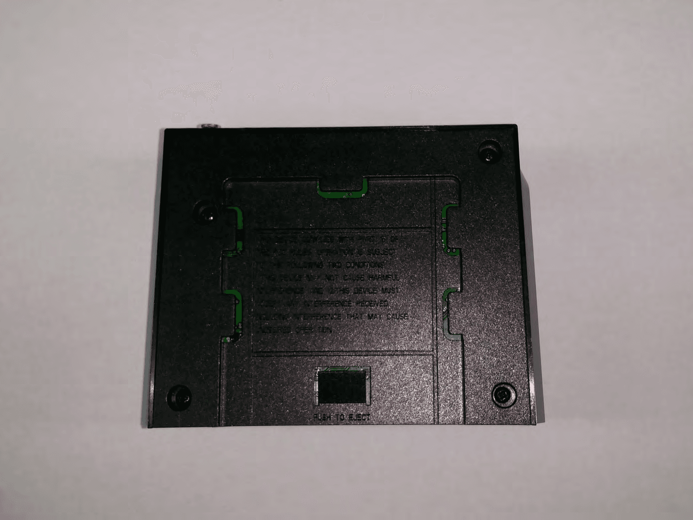
Label of location
Internal Photos
* ANTENNA POSITION* ANTENNA POSITION
RF Exposure Info
According to KDB 447498 D01 General RF Exposure Guidance v05, section 4.3.1 At 100 ㎒ to 6 ㎓ and for test separation distances ≤ 50 mm, the SAR test exclusion threshold is determined according to the following; a) [(max. power of channel, including tune-up tolerance, ㎽) / (min. test separation distance, mm)] x [√f(GHz)] ≤ 3.0 1. SAR test exclusion threshold Frequency : 2462 ㎒ (min. separation distances = 5 mm) SAR test exclusion thresholds(5 mm) = [(9.55 / 5) * √2.412] = 2.966 ≤ 3.0 Mode Frequency (MHz) Tune up output Power (dBm) Measured max output power (dBm) Separation Distance (mm) ≤ 3.0 802.11n24128.809.7652.94 802.11n24368.809.2952.64 802.11n24628.808.1352.05 2. Conclusion : WL SAR was not required SAR test exclusion [Tune up power, dBm ] = [Target power, dBm ± tune-up tolerance, dBm)] Maximum tuned up power = ( 8.80 dBm ± 1 dBm) = 9.8 dBm = 9.55 mW Measured max output power = 9.76 dBm
Test Report
3 4 5 6 10 10 10 10 11 13 13 13 13 14 14 14 14 7.2 Test instruments and measurement setup .................................................................. ... 7.3 Measurement results ................................................................................................ 7.1 Test procedure ...................................................................................................... 5.4 Trace data ............................................................................................................ ... 6. Maximum Peak Output Power .......................................................................................... 6.1 Test procedure ...................................................................................................... 6.2 Test instruments and measurement setup .................................................................. ... 6.3 Measurement results ................................................................................................ 7. Maximum conducted (average) output power ..................................................................... 5.3 Measurement results ................................................................................................ 5.1 Test procedure ...................................................................................................... 5.2 Test instruments and measurement setup .................................................................. ... 4. Measurement condition ................................................................................................ 5. DTS bandwidth ......................................................................................................... ... Contents 1. Laboratory Information ................................................................................................... 2. Description of EUT ...................................................................................................... 3. Test Standards ......................................................................................................... ... 15 18 18 18 18 19 21 21 21 21 22 26 26 26 27 28 36 11.1 Measurement equipment ....................................................................................... 36 11.2 Environmental conditions .................................................................................... ...36 37 38 38 39 40 41 12.4. Photographs of EUT ............................................................................................. ... Appendix 1. Special diagram 11. Measurement of conducted emission ........................................................................... Report Number : ESTF151508-001 , Web : www. estech. co. kr Page 2 of 41 10.1 Measurement equipment ....................................................................................... ... 10.3 Measurement Instrument setting for Radiated Emission ................................................ 10.4 Test Data ............................................................................................................... 11.3 Test Data ............................................................................................................... 10.2 Environmental conditions .......................................................................................... Appendix 2. Antenna Requirement 12. Photographs of test setup ....................................................................................... ... 12.1.Setup for Radiated Test : (30 ~ 1 000) MHz ............................................................ 12.2.Setup for Radiated Test : Above 1 GHz .................................................................. 12.3. Setup for Conducted Test : (0.15 ~ 30) MHz............................................................ ... 9. Emissions in non-restricted frequency bands .................................................................. 8.1 Test procedure ......................................................................................................... 8.4 Trace data ............................................................................................................... 10. Measurement of radiated emission ................................................................................. 8. Maximum power spectral density level in the fundamental emission ....................................... 9.2 Test instruments and measurement setup ..................................................................... 9.3 Measurement results ................................................................................................ 9.4 Trace data of band-edge & out of emissioin ............................................................... 9.1 Test procedure ...................................................................................................... ... 8.3 Measurement results ................................................................................................ 8.2 Test instruments and measurement setup .................................................................. ... 7.4 Trace data(Peak, Average).......................................................................................... EST-QP-20-01(2)-(F15) 1. Laboratory Information 1.1 General 1.2 Test Lab. Corporation Name : ESTECH Co., Ltd. This EUT (Equipment Under Test) has been shown to be capable of compliance with the applicable technical standards and is tested in accordance with the measurement procedures as indicated in this report. ESTECH Lab attests to accuracy of test data. All measurement reported herein were performed by ESTECH Co., Ltd. ESTECH Lab assume full responsibility for the completeness of these measurements and vouch for the qualifications of all persons taking them. Head Office : Suite 1015 World Meridian II, 123 Gasan Digital 2-ro, Geumcheon-gu, Seoul 153-759, R. O. Korea EMC/Telecom/Safety Test Lab : 347-69, Jungbu-daero 147b…
Text truncated - open the document above for the full version.
Test Setup Photos
1. Photographs of test setup (802.11n) 1-1.Setup for Radiated Test : 30 ~ 1 000 MHz [ Front ] TEST SETUP PHOTO [ Rear ] 1-2.Setup for Radiated Test : Above 1 GHz [ Front ] [ Rear ] 1-3.Setup for Conducted Test : 0.15 ~ 30 MHz [ Front ] [ Rear ]
Contact Information
Applicant
Ahnse Lee(Director of R & D Center)
Test Firm
ESTECH Co., Ltd.Yang Jinmo
Technical Specifications
| # | Rule Parts | Frequency Range | Power Output |
|---|---|---|---|
| 1 | 15C | 2.41 GHz - 2.46 GHz | 9.46 mW |
Other Applications from Trinus Systems Inc.
ROY3102PNARE
Apr 28, 2014Wireless Transceiver System
Equipment Class
DSS - Part 15 Spread Spectrum Transmitter
ROY3101PNATR
Apr 28, 2014Wireless Transceiver System
Equipment Class
DSS - Part 15 Spread Spectrum Transmitter
ROYCCR24RMOT
Dec 21, 2010Wireless Microphone System - Base Receiver
Equipment Class
DSS - Part 15 Spread Spectrum Transmitter
ROYTPRF-900H
Dec 15, 2003Wireless Transceiver System, Handset
Equipment Class
DXX - Part 15 Low Power Communication Device Transmitter
ROYTPRF-900B
Dec 15, 2003Wireless Transceiver System, Base Station
Equipment Class
DXX - Part 15 Low Power Communication Device Transmitter