RPARFA3ARF-Module (RFID Tag Reader/Writer)
Riso Kagaku Corporation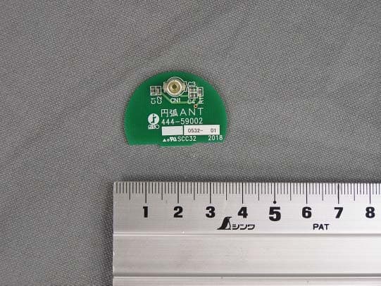
Click to zoom
Application Details
- Equipment Class
- DXT - Part 15 Low Power Transceiver, Rx Verified
- Date of Grant
- Sep 08, 2005
- Application Purpose
- Original Equipment
- Date of Application
- Sep 08, 2005
- Equipment Note
- RF-Module (RFID Tag Reader/Writer)
- Frequency Range
- 13.56000000 - 13.56000000
- Company
- Riso Kagaku Corporation
- Country
- Japan
Documents & Files
Document Text
Text extracted from the exhibit documents filed with the FCC. Open a document above to read the original.
Users Manual
1 RF-MODULE-3CH-V3A(Type: 045-50025) User’s Manual Ver. 1.0 Riso Kagaku Corporation 2 This manual describes the use, the functions and the performance of the Radio Frequency Identification System RF-MODULE-3CH-V3A. The system is so manufactured that it can not be repaired or replaced by the user; and therefore, if there are such needs, please contact Riso Kagaku Corporation or its agent. No service work should be started before the service person has read this manual. Features This product uses radio frequency of 13.56 MHz to communicate with the tags; thus, it should conform to any relative laws and regulations of the country or the region. Authorization of the module or the printer into which the module is installed may be required in some countries or regions. Cautions 1. Use or store this product on the temperature and humidity conditions mentioned below, so as to maintain its operational reliability. 2. Use or store this product in an environment free of explosive gases, inflammable gases, corrosive gases, oils, organic solvents, dust, salt and metal powders. 3. Keep this product free of direct shock, strong vibration or sunshine. 4. To communicate with the tags, this product uses 13.56 MHz radio frequency, which may be interfered by radio waves (noises) emitted from a transceiver, a motor, a monitor, a power supply (including a power supply IC), etc. Please make sure that such interferences will not occur before using the product in a place near to these devices. 5. Take proper measures to avoid any possible electrostatic discharge to the product, which may damage the product. 6. After doing the wiring, make sure the connectors are fastened properly. Warning Do not alter any part of the product. Alteration of the printed wiring board, the antennas or the connecting cables of the module may damage the control board of the printer, and is an illegal act if it causes the modular transmitter emissions out of the limits provided by laws or regulations. Specifications 3 Dimensions Less than 60 x 70 x 14.2 mm Transmitting Frequency 13.56 MHz Transmission field strength Less than 500 μV/m at 3m Operating Temperature 0 to +50 o C Storage Temperature -20 to +60 o C Operating Humidity 25 to 85% RH (Without condensation) Supply voltage 5 V dc +/- 10% Discarding the Product The product should be discarded as normal printed wiring boards. If you do not know how such boards should be discarded, ask Riso Kagaku Corporation, its agent or the government. Notice about the law and the standard FCC ID: RPARFA3A This device complies with Part 15 of the FCC Rules. Operation is subject to the following two conditions: (1) this device may not cause harmful interference, and (2) this device must accept any interference received, including interference that may cause undesired operation. The user is cautioned that unauthorized changes or modifications not approved could void the user's authority to operate the equipment. Canada IC: 4819A-RFA3A Operation is subject to the following two conditions: (1) this device may not cause interference, and (2) this device must accept any interference, including interference that may cause undesired operation of the device.
Cover Letter(s)
RISO KAGAKU CORPORATION FCC ID: RPARFA3A Request for transmitter modular approval Characteristics of the Modular Transmitter Item Requirements Does the EUT meet the requirement? 1 Have its own RF shielding This module is not required to have its own RF shielding to meet FCC emission requirements. It was tested in a stand alone configuration without external shielding. 2 Have buffered modulation/data inputs (if such inputs are provided) All inputs to the module are buffered through logic or microprocessor inputs. 3 Have its own power supply regulation This module has own power supply regulation. 4 Meet the antenna requirements of Section 15.203 The requirements are not met; however, the module is so configured that it is impossible for the user to replace the antennas. 5 Be tested in a stand-alone configuration, i.e., the antenna, AC or DC power and data input/output lines must be connected to the module but, the module must not be inside another case during testing This modular transmitter was tested in a stand-alone configuration outside the host device during testing. The host device is an ac-powered unit intended to be used as office/business printer. 6 Be labeled with its own FCC ID number, and if the FCC ID is not visible when the module is installed inside another device, then the outside of the device into which the module is installed must also display a label referring to the enclosed module. This modular transmitter is labeled with its own FCC ID number, and, as the FCC ID is not visible when the module is installed into the host device, the host device bears a label wording: “Contains FCC ID:RPARFA3A” 7 The modular transmitter is manufactured so that the user cannot influence the operation of the transmitter that will operate outside of the scope of the regulations. The module is so manufactured. 8 Address compliance with the Commission's RF exposure limits in Sections 2.1091 and 2.1093. In addition, spread spectrum transmitters operating under Section 15.247 are required to address RF exposure compliance in accordance with Section 15.247(b)(4). The module is not subject to 2.1091, 2.1093 or 15.247. (It is not mobile, portable, or spread spectrum transmitter.)
External Photos
FCC ID: RPARFA3A 045-50025 (RF-MODULE-3CH-V3A) Component side FCC ID: RPARFA3A 444-59002 (D-Shape Antenna) Component side FCC ID: RPARFA3A 444-59006 (O-Shape Antenna) Component side FCC ID: RPARFA3A 045-50025 (RF-MODULE-3CH-V3A) Solder side FCC ID: RPARFA3A 444-59002 (D-Shape Antenna) Solder side FCC ID: RPARFA3A 444-59006 (O-Shape Antenna) Solder side
ID Label/Location Info
FCC ID: RPARFA3A FCC ID LABEL AND LOCATION FCC ID Label for 045-50025(RF-MODULE-3CH-V3A) FCC ID LABEL LOCATION 16mm 17.5mm
Internal Photos
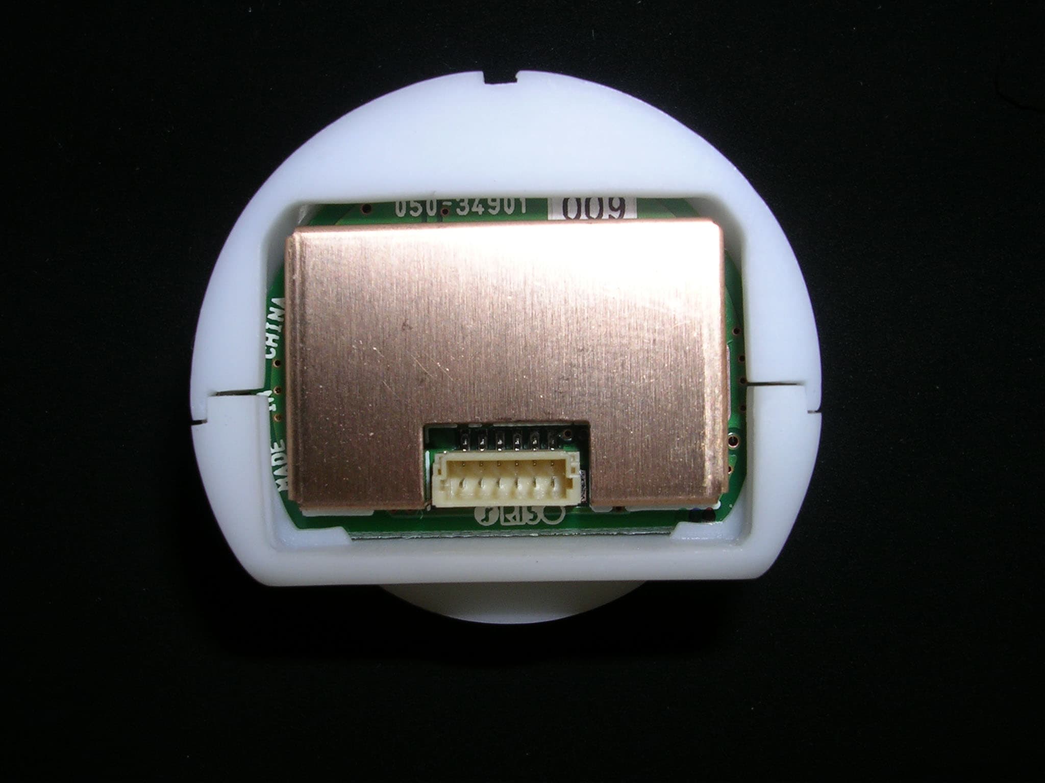
FCC ID: RPARFA3A 045-50025 (RF-MODULE-3CH-V3A) Component side FCC ID: RPARFA3A 444-59002 (D-Shape Antenna) Component side FCC ID: RPARFA3A 444-59006 (O-Shape Antenna) Component side FCC ID: RPARFA3A 045-50025 (RF-MODULE-3CH-V3A) Solder side FCC ID: RPARFA3A 444-59002 (D-Shape Antenna) Solder side FCC ID: RPARFA3A 444-59006 (O-Shape Antenna) Solder side
Test Report
JAPAN QUALITY ASSURANCE ORGANIZATION 2096, OHATA, TSURU-SHI, YAMANASHI 402-0045, JAPAN PHONE +81-554-43-5517, FAX +81-554-43-6316 JQA File No.: 441-50438 Issue Date : August 9, 2005 Page 1 of 28 EMI TEST REPORT JQA File No. : 441-50438 Model No. : 045-50025 Type of Equipment : RF-Module (RFID Tag Reader/Writer) Regulations Applied : CFR 47 FCC Rules and Regulations Part 15 FCC ID : RPARFA3A Applicant : RISO KAGAKU CORPORATION Address : 127-7, Taninosawa, Fukuda, Ami-machi, Inashiki-gun, Ibaraki-ken 300-1156, Japan Manufacture : RISO KAGAKU CORPORATION Address : 127-7, Taninosawa, Fukuda, Ami-machi, Inashiki-gun, Ibaraki-ken 300-1156, Japan Received date of EUT : July 23, 2005 Final Judgment : Passed TEST RESULTS IN THIS REPORT are obtained in use of equipment that is traceable to National Institute of Advanced Industrial Science and Technology (AIST) of Japan and National Institute of Information and Communications Technology (NICT) of Japan. The test results only responds to the tested sample. THIS REPORT should not be reproduced, except in full, without the approval of the JQA Safety & EMC Center EMC Engineering Department TSURU EMC Branch. JQA File No.: :441-50438 FCC ID : :RPARFA3A Model No. :045-50025 Issue Date August 9, 2005 Standard :CFR 47 FCC Rules Part 15 Page 2 of 28 JAPAN QUALITY ASSURANCE ORGANIZATION TABLE OF CONTENTS Page 1 Documentation 1.1 Test Regulation 3 1.2 General Information 3 1.3 Test Condition 4 – 8 1.4 EUT Modifications / Deviation from Standard 9 1.5 Test results 10 1.6 Summary 11 1.7 Test Configuration / Operation of EUT 12 1.8 EUT Arrangement(Drawing) 13 1.9 Preliminary Test and Test-setup (Drawings) 14 – 18 1.10 EUT Arrangement (Photographs) 19 - 21 2 Test Data 2.1 AC Power Line Conducted Emission 0.45 MHz – 30 MHz 22 – 23 2.2 Radiated Emission (Electric Field)9 kHz – 30 MHz 24 2.3 Radiated Emission (Electric Field)30 MHz – 1000 MHz 25 - 26 2.4 Radiated Emission (Electric Field) Above 1 GHz N/A 2.5 Frequency Stability 27 2.6 Occupied Bandwidth 28 2.7 AC Power Line Conducted Emissions for Receiver N/A 2.8 Spurious Emissions for Receiver (Radiation) see note note : refer to pages 10 and 25pages JQA File No.: :441-50438 FCC ID : :RPARFA3A Model No. :045-50025 Issue Date August 9, 2005 Standard :CFR 47 FCC Rules Part 15 Page 3 of 28 JAPAN QUALITY ASSURANCE ORGANIZATION 1 DOCUMENTATION 1.1 TEST REGULATION FCC Rules and Regulations Part 15 Subpart A and C (January 8, 2004) Intentional Radiators Test procedure : AC power line conducted emission, radiated emission, frequency stability and occupied bandwidth tests were performed according to the procedures in ANSI C63.4-2003. 1.2 GENERAL INFORMATION 1.2.1 Test facility : 1) Test Facility located at JQA Safety & EMC Center EMC Engineering Department TSURU EMC Branch : Open Site No.1, No.2, An Anechoic Chamber (3 m and 10 m, on common plane) and a Shielded Room FCC Registration Number: 342182 (Date of Listing : March 30, 2005) 2) JQA Safety & EMC Center EMC Engineering Department TSURU EMC Branch is recognized under the National Voluntary Laboratory Accreditation Program for satisfactory compliance established in title 15, Part 285 Code of Federal Regulations. NVLAP Lab Code : 200192-0 (Effective through : June 30, 2006) 1.2.2 Description of the Equipment Under Test (EUT) : 1) Type of Equipment : RF-Module (RFID Tag Reader/Writer) 2) Product Type : Prototype 3) Category : Low Power Communication Device 4) EUT Authorization : Certification 5) FCC ID : RPARFA3A 6) Trade Name : RISO 7) Model No. : 045-50025 8) Operating Frequency Range : 13.56 MHz 9) Highest Frequency Used in the EUT : 13.56 MHz 10) Serial No. : FL13 11) Date of Manufacture : - 12) Power Rating : 5.0VDC(*) 13) EUT Grounding : None *The EUT was operated with the host printer.(Input: 120Vac 60Hz, Output: 5.0Vdc) 1.2.3 Definitions for symbols used in this test report : X - indicates that the listed condition, standard or equipment is applicable for this report. - indicates that the listed condition, standard or equipment is not applicable for this report. JQA File No.: :441-50438 FCC ID : :RPARFA3A Model No. :045-50025 Issue Date August 9, 2005 Standard :CFR 47 FCC Rules Part 15 Page 4 of 28 JAPAN QUALITY ASSURANCE ORGANIZATION 1.3 TEST CONDITION 1.3.1 The measurement of the AC Power Line Conducted Emission X - was performed in the following test site. - was not applicable. Test location : JQA Safety & EMC Center EMC Engineering Department TSURU EMC Branch 2096 Ohata, Tsuru-shi Yamanashi-ken 402-0045, JAPAN - Shielded Room A - Shielded Room B X - Anechoic Chamber - Open Site No.1 - Open Site No.2 Used test instruments : Type Model No.Manufacturer Serial No. Last Cal. Interval X - Test Receiver (R-3) ESI7 Rohde & Schwarz 100059 2004/11 1 Year - Test Receiver (R-4) ESHS30 Rohde & Schwarz 842053/001 2005/2 1 Year - Test Receiver (R-5) ESCS30 Rohde & Schwarz 100203 2005/2 1 Year - AMN (L-1) KNW-407 Kyoritsu Electrical8-833-5 2004/10 1 Year - AMN (L-2) KNW-407 Kyoritsu Electrical8-680-14 2004/10 1 Year X - AMN (L-3) KNW-407 Kyoritsu Electrical8-757-1 2005/6 1 Year - AMN (L-4) KNW-242 Kyoritsu Electrical8-755-1 2005/6 1 Year - AMN (L-5) KNW-242C Kyoritsu Electrical8-837-14 2005/6 1 Year - AMN (L-6) KNW-243C Kyoritsu Electrical8-692-5 2004/9 1 Year - AMN (L-7) KNW-243C Kyoritsu Electrical8-831-3 2005/6 1 Year - AMN (L-8) KNW-243C Kyoritsu Electrical8-831-4 2005/6 1 Year - AMN (L-9) KNW-243C Kyoritsu Electrical8-831-2 2004/9 1 Year - ISN (L-10) ENY41 Rohde & Schwarz 0830663/046 2005/2 1 Year - ISN (L-11) ENY22 Rohde & Schwarz 0830661/029 2005/2 1 Year X - RF Cable (CB-3) 3D-2W Fujikura - 2005/5 1 Year - RF Cable (CB-4) 3D-2W Fujikura - 2005/5 1 Year - RF Cable (CB-5) 3D-2W Fujikura - 2005/5 1 Year X - Pulse Limiter (PL-3) ESH3-Z2 Rohde & Schwarz - 2004/11 1 Year - Pulse Limiter (PL-4) ESH3-Z2 Rohde & Schwarz - 2005/2 1 Year - Pulse Limiter (PL-5) ESH3-Z2 Rohde & Schwarz - 2005/2 1 Year - 50ohm Termination(TM-1) BNC-P-1.5 TDC - 2005/3 1 Year - 50ohm Termination(TM-2…
Text truncated - open the document above for the full version.
Test Setup Photos
JAPAN QUALITY ASSURANCE ORGANIZATION 2096, OHATA, TSURU-SHI, YAMANASHI 402-0045, JAPAN PHONE +81-554-43-5517, FAX +81-554-43-6316 JQA File No.: 441-50438 Issue Date : August 9, 2005 Page 1 of 28 EMI TEST REPORT JQA File No. : 441-50438 Model No. : 045-50025 Type of Equipment : RF-Module (RFID Tag Reader/Writer) Regulations Applied : CFR 47 FCC Rules and Regulations Part 15 FCC ID : RPARFA3A Applicant : RISO KAGAKU CORPORATION Address : 127-7, Taninosawa, Fukuda, Ami-machi, Inashiki-gun, Ibaraki-ken 300-1156, Japan Manufacture : RISO KAGAKU CORPORATION Address : 127-7, Taninosawa, Fukuda, Ami-machi, Inashiki-gun, Ibaraki-ken 300-1156, Japan Received date of EUT : July 23, 2005 Final Judgment : Passed TEST RESULTS IN THIS REPORT are obtained in use of equipment that is traceable to National Institute of Advanced Industrial Science and Technology (AIST) of Japan and National Institute of Information and Communications Technology (NICT) of Japan. The test results only responds to the tested sample. THIS REPORT should not be reproduced, except in full, without the approval of the JQA Safety & EMC Center EMC Engineering Department TSURU EMC Branch. JQA File No.: :441-50438 FCC ID : :RPARFA3A Model No. :045-50025 Issue Date August 9, 2005 Standard :CFR 47 FCC Rules Part 15 Page 2 of 28 JAPAN QUALITY ASSURANCE ORGANIZATION TABLE OF CONTENTS Page 1 Documentation 1.1 Test Regulation 3 1.2 General Information 3 1.3 Test Condition 4 – 8 1.4 EUT Modifications / Deviation from Standard 9 1.5 Test results 10 1.6 Summary 11 1.7 Test Configuration / Operation of EUT 12 1.8 EUT Arrangement(Drawing) 13 1.9 Preliminary Test and Test-setup (Drawings) 14 – 18 1.10 EUT Arrangement (Photographs) 19 - 21 2 Test Data 2.1 AC Power Line Conducted Emission 0.45 MHz – 30 MHz 22 – 23 2.2 Radiated Emission (Electric Field)9 kHz – 30 MHz 24 2.3 Radiated Emission (Electric Field)30 MHz – 1000 MHz 25 - 26 2.4 Radiated Emission (Electric Field) Above 1 GHz N/A 2.5 Frequency Stability 27 2.6 Occupied Bandwidth 28 2.7 AC Power Line Conducted Emissions for Receiver N/A 2.8 Spurious Emissions for Receiver (Radiation) see note note : refer to pages 10 and 25pages JQA File No.: :441-50438 FCC ID : :RPARFA3A Model No. :045-50025 Issue Date August 9, 2005 Standard :CFR 47 FCC Rules Part 15 Page 3 of 28 JAPAN QUALITY ASSURANCE ORGANIZATION 1 DOCUMENTATION 1.1 TEST REGULATION FCC Rules and Regulations Part 15 Subpart A and C (January 8, 2004) Intentional Radiators Test procedure : AC power line conducted emission, radiated emission, frequency stability and occupied bandwidth tests were performed according to the procedures in ANSI C63.4-2003. 1.2 GENERAL INFORMATION 1.2.1 Test facility : 1) Test Facility located at JQA Safety & EMC Center EMC Engineering Department TSURU EMC Branch : Open Site No.1, No.2, An Anechoic Chamber (3 m and 10 m, on common plane) and a Shielded Room FCC Registration Number: 342182 (Date of Listing : March 30, 2005) 2) JQA Safety & EMC Center EMC Engineering Department TSURU EMC Branch is recognized under the National Voluntary Laboratory Accreditation Program for satisfactory compliance established in title 15, Part 285 Code of Federal Regulations. NVLAP Lab Code : 200192-0 (Effective through : June 30, 2006) 1.2.2 Description of the Equipment Under Test (EUT) : 1) Type of Equipment : RF-Module (RFID Tag Reader/Writer) 2) Product Type : Prototype 3) Category : Low Power Communication Device 4) EUT Authorization : Certification 5) FCC ID : RPARFA3A 6) Trade Name : RISO 7) Model No. : 045-50025 8) Operating Frequency Range : 13.56 MHz 9) Highest Frequency Used in the EUT : 13.56 MHz 10) Serial No. : FL13 11) Date of Manufacture : - 12) Power Rating : 5.0VDC(*) 13) EUT Grounding : None *The EUT was operated with the host printer.(Input: 120Vac 60Hz, Output: 5.0Vdc) 1.2.3 Definitions for symbols used in this test report : X - indicates that the listed condition, standard or equipment is applicable for this report. - indicates that the listed condition, standard or equipment is not applicable for this report. JQA File No.: :441-50438 FCC ID : :RPARFA3A Model No. :045-50025 Issue Date August 9, 2005 Standard :CFR 47 FCC Rules Part 15 Page 4 of 28 JAPAN QUALITY ASSURANCE ORGANIZATION 1.3 TEST CONDITION 1.3.1 The measurement of the AC Power Line Conducted Emission X - was performed in the following test site. - was not applicable. Test location : JQA Safety & EMC Center EMC Engineering Department TSURU EMC Branch 2096 Ohata, Tsuru-shi Yamanashi-ken 402-0045, JAPAN - Shielded Room A - Shielded Room B X - Anechoic Chamber - Open Site No.1 - Open Site No.2 Used test instruments : Type Model No.Manufacturer Serial No. Last Cal. Interval X - Test Receiver (R-3) ESI7 Rohde & Schwarz 100059 2004/11 1 Year - Test Receiver (R-4) ESHS30 Rohde & Schwarz 842053/001 2005/2 1 Year - Test Receiver (R-5) ESCS30 Rohde & Schwarz 100203 2005/2 1 Year - AMN (L-1) KNW-407 Kyoritsu Electrical8-833-5 2004/10 1 Year - AMN (L-2) KNW-407 Kyoritsu Electrical8-680-14 2004/10 1 Year X - AMN (L-3) KNW-407 Kyoritsu Electrical8-757-1 2005/6 1 Year - AMN (L-4) KNW-242 Kyoritsu Electrical8-755-1 2005/6 1 Year - AMN (L-5) KNW-242C Kyoritsu Electrical8-837-14 2005/6 1 Year - AMN (L-6) KNW-243C Kyoritsu Electrical8-692-5 2004/9 1 Year - AMN (L-7) KNW-243C Kyoritsu Electrical8-831-3 2005/6 1 Year - AMN (L-8) KNW-243C Kyoritsu Electrical8-831-4 2005/6 1 Year - AMN (L-9) KNW-243C Kyoritsu Electrical8-831-2 2004/9 1 Year - ISN (L-10) ENY41 Rohde & Schwarz 0830663/046 2005/2 1 Year - ISN (L-11) ENY22 Rohde & Schwarz 0830661/029 2005/2 1 Year X - RF Cable (CB-3) 3D-2W Fujikura - 2005/5 1 Year - RF Cable (CB-4) 3D-2W Fujikura - 2005/5 1 Year - RF Cable (CB-5) 3D-2W Fujikura - 2005/5 1 Year X - Pulse Limiter (PL-3) ESH3-Z2 Rohde & Schwarz - 2004/11 1 Year - Pulse Limiter (PL-4) ESH3-Z2 Rohde & Schwarz - 2005/2 1 Year - Pulse Limiter (PL-5) ESH3-Z2 Rohde & Schwarz - 2005/2 1 Year - 50ohm Termination(TM-1) BNC-P-1.5 TDC - 2005/3 1 Year - 50ohm Termination(TM-2…
Text truncated - open the document above for the full version.
Contact Information
Applicant
Tomokazu Sugiyama(Regulation Manager)
Test Firm
Japan Qlty. Assur. Org. Safety & EMC CtrHideki Kajiwara
Technical Specifications
| # | Rule Parts | Frequency Range | Power Output | Tolerance |
|---|---|---|---|---|
| 1 | 15C | 13.56 MHz - 13.56 MHz | - | 0.0100000000 % |
Other Applications from Riso Kagaku Corporation
RPARFR6
Sep 09, 2008RFID Tag Reader/Writer
Equipment Class
DXX - Part 15 Low Power Communication Device Transmitter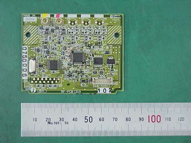
RPARFA3B
Feb 03, 2008RF Module(RFID Tag Reader/Writer)
Equipment Class
DXT - Part 15 Low Power Transceiver, Rx Verified
RPARFOM5
Sep 05, 2007RF Module(RFID Tag Reader/Writer)
Equipment Class
DXX - Part 15 Low Power Communication Device Transmitter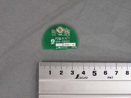
RPARFA3
Sep 05, 2005RF-Module (RFID TAG Reader/Writer)
Equipment Class
DXT - Part 15 Low Power Transceiver, Rx Verified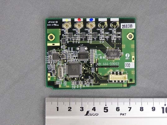
RPARFMHL00
Mar 07, 2004RFID Tag Reader / Writer
Equipment Class
DXT - Part 15 Low Power Transceiver, Rx Verified