RR7CLBLUEHOOKBluetooth Earphone
Great Well Electronic Limited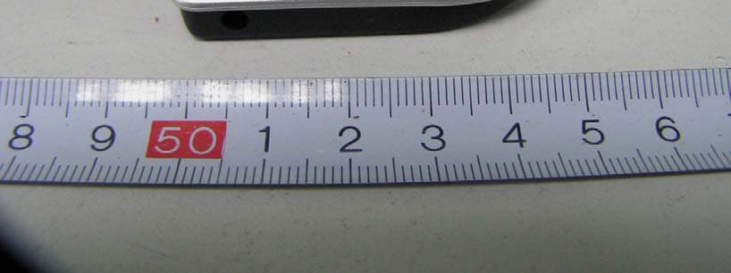
Click to zoom
Application Details
- Equipment Class
- DSS - Part 15 Spread Spectrum Transmitter
- Date of Grant
- Aug 07, 2007
- Application Purpose
- Original Equipment
- Date of Application
- Aug 07, 2007
- Equipment Note
- Bluetooth Earphone
- Frequency Range
- 2402.00000000 - 2480.00000000
- Country
- China
Documents & Files
Document Text
Text extracted from the exhibit documents filed with the FCC. Open a document above to read the original.
Users Manual
CL BlueHook User's Manual 1. Introduction 1.1 Bluetooth introduction 1.2 Headset Picture 1.3 indicator specification 2. Operation Instruction 2.1Bluetooth headset pairing 2.2 Wearing 2.3 How to receive a call 2.4 How to end a call 2.5 How to reject a call 2.6 How to dial a call 2.7 How to redial last call 2.8 Voice transition from mobile phone to headset 2.9 How to open Bluetooth headset 2.10 How to close Bluetooth headset 2.11 How to adjust volume in speaking 2.12 How to charge battery of CL BlueHook 3. Specification 4. Appendix 1、 Introduction 1.1 Bluetooth introduction Bluetooth is nickname of king in Denmark in the Dark Ages. Bluetooth technology is ISM frequency working in global common 2.4GHz frequency. It provides low cost, close wireless communication and forms personal network in communication environment of fixed and mobile devices to realize seamless resource sharing for kinds of devices nearby. CL BlueHook is a standard headset in accordance with Bluetooth 2.0+EDR and supports Headset and Headsfree at the same time. The working effective range is within 10m. 1.2 Headset Picture It can realize speaking function when you use press-key on CL BlueHook Bluetooth headset and no need to touch mobile phone. Vo l u m e increase key Transparent LED plastic sheet Charging Port Multifunction speaking key Microphone Volume reduction key Audio output cord 1.3 indicator specification Indicator Headset state it flashes blue every 3sec. Headset is in power on state and can not be used now. Blue and red flash alternately Headset is in standby state and waits for connection with mobile phone. After blue and red flash alternately, blue light flashes 8 times continuously Connection between headset and mobile phone. it flashes blue every 2sec. Headset is in standby state and can be used. it flashes red slowly. low battery for headset 2. Operation Instruction 2.1Bluetooth headset pairing “Pairing” is a Bluetooth term and refers to let your Bluetooth device make wireless communication by simple setting, inform chain circuit, your headset can only make wireless speaking with mobile phone. Pairing only needs to make once. Then, you open mobile phone every time; CL BlueHook will connect with mobile phone automatically. If it shows “whether connection BT-019 or not” on mobile phone, you only need to press Confirm Button on mobile phone. a.Make sure headset is in power-on mode. ( Details as 2.9 How to open headset) b.Make sure without other Bluetooth devices in pairing mode within 10m. c.Long press “VOL + and VOL-” about 3sec till BLUE AND RED LED flash alternatively. Loose “VOL + and VOL-”, headset is in waiting mode. d.Choose Bluetooth on the connection type of Bluetooth mobile phone, after entry menu, choose “lookup and search pairing device” (Details as Bluetooth mobile phone specification) e. Then,press Confirm on mobile phone, it shows “input ID Code” on screen of mobile phone,please enter PIN Code“0000”;When BLUE LED of Bluetooth headset flashes slowly, it means successful pairing. The headset is in standby mode and can be used normally. Note:If RED LED of headset flashes, it shows low battery of Bluetooth headset. 2.2 Wearing CL BLUEHOOK Bluetooth headset: With clip type design, you can clip CL BlueHook on clothes and wear earphone on left and right ear if you like. 2.3 Receiving a phone call When there is an incoming call, press the Multi-function Button once to answer the phone call. 2.4 How to end a phone call During a phone call, press the Multi-function Button once to answer the phone call. 2.5 Refuse an incoming call After hearing indication voice for incoming call, press VOL- for 3sec. Note: the function needs mobile phone to support. 2.6 Make a call a.Make a call through mobile phone, set up on mobile phone firstly, send calling to handsfree or headset, then dial number as usual, begin speaking after answer, headset will connect automatically. If end up a call, press the Multi-function Button. b.Make a call by voice command (only apply to mobile phone supported the function). Firstly, connect headset by handsfree operation. Secondly, long press VOL+, you will hear voice prompt. Then speak name and telephone number loudly and clearly to microphone on headset. If there is trained voice command on mobile phone, it can dial telephone you want. 2.7 Redial the last calling phone Press “VOL -” for 3sec, redial the last telephone number after hearing the voice. Note: a.Mobile phone has not any incoming call and is not in speaking mode. b.The function only works on Bluetooth mobile phone under application mode of handsfree. 2.8 Voice transfer from headset to mobile phone When you need to use mobile phone to make a call, please press VOL+. The voice has transferred from headset to mobile phone after hearing the voice for 3sec. 2.9 How to open headset When using headset again, you need not to pair headset with mobile phone and only need to open headset to connect automatically. Power-on method: press Multifunction Speaking Button for 5sec until BLUE LED flashes, then loose. If successful connection, BLUE LED flashes 3 times every 3sec, it shows headset can open telephone or be in standby mode. Note:RED LED will flashes if low battery. 2.10 Close headset Press Multifunction Speaking Button about 3sec till RED LED flashed, you will hear a voice from headset and then loose Multifunction Speaking Button, the headset will power off now. 2.11 Adjust volume Add volume during speaking, you need press VOL+ lightly; reduce volume during speaking, you need press VOL- lightly. 2.12 Charging battery When you use CL BlueHook for the first time, please charging over 3hrs till RED LED is put off. During charging, please not to make other application at the same time. When use CL BlueHook again, charging about 3hrs. Please insert charger to charging port on CL BlueHook. During charging, RED LED will flash. When charging is over, LED will put off and battery is full charge. ▲ Note: A.When RED LED will flash in standb…
Text truncated - open the document above for the full version.
Block Diagram
Block Diagram 1.8VPower supply Charge DC charge Interface Battery RF Receiver RF Transmitter RISC MICROCONTROLLOR AUDIO CODEC USB Interface SPI Interface UART Interface PIO Interface AIO Interface RF Filter PCM Interface SPEAKER Clock Generation 16MHZ Crystal 2.402-2.4800GHZ 2.7VLDO
External Photos
External Photos EUT – Front View EUT – Back View
ID Label/Location Info
ID Label/Location FCC ID Label Label Location Information Specifications : Text is Black or white in color and is left justified. Labels are printed in indelible ink on permanent adhesive backing or silk-screened onto the EUT or shall be affixed at a conspicuous location on the EUT. Label Location: FCC ID: RR7CLBlueHook
Internal Photos
Internal Photos EUT – Cover off View EUT –Main Board Top View EUT –Main Board Bottom View Battery View
Operational Description
Operational principle 1. CPU,U2,BC413159A11: CSR BlueCore-04-Audio-rom BC413159A11QFN, ①Key Features Radio -Operation with common TX/RX terminal simplifies external matching circuitry and eliminates external antenna switch -Bist minimizes production test time -No external trimming is required in production -Full RF reference designs are available -Bluetooth V2.0+EDR specification compliant ②Transmitter +6dBm RF transmit power with level control from on-chip 6-bit DAC over a dynamic range >30dB -Supports Class 2 and Class 3 radios without the need for an external power amplifier or TX/RX switch -Support Class 1 radio with an external power amplifier provided by a power control terminal controlled by an internal 8-bit voltage DAC and an external RF TX/RX switch ③Receiver -Integrated channel filters -Digital demodulator for improved sensitivity and co-channel rejection -Digitized RSSI available in real time over the HCI interface -Fast AGC for enhanced dynamic range ④Synthesizer -Fully integrated synthesizer, no external VCO varactor diode or resonator -Compatible with crystals between 8 and 32MHz (in multiples of 250KHz) or an external clock ⑤Baseband and software -Internal 6Mbit ROM -Internal 48kb RAM to support EDR..allows full speed Bluetooth data transfer, mixed voice and data and full piconet operation -Logic for forward error correction, header error control, access code correlation, CRC,demodulation, encryption bit-stream generation, whitening and transmit pulse shaping -Transponders for A-law, μ-law and linear voice from host and A-law, μ-law and CVSD voice over air ⑥Physical Interfaces -Synchronous serial interface up to 4Mbaud for system debugging -UART interface with programmable Baud rate up to 3Mbaud with an optional bypass mode -Full speed USB v1.1 interface supports OHCI and UHCI host interfaces. Compliant with USB v2.0-optional I 2 C TM compatible interface ⑦Audio Codec -15-bit resolution, 8KHz sampling frequency -Digital enhancements to add bass cut,side tone and treble boost -Analogue enhancements to support single-ended speaker drive capability and reference availability ⑧Operation Principle: Low power 1.8v operation Operation clock is provided by 16MHz oscillator. 2. EEPROM ,U1, CAT24C32, 32kb I 2 C CMOS serial eeprom.It is used to store the normal and test firmware. 3. power supply:3.7V Recharger Lithium battey,U3 2.7VLDO Voltage to micphone 4. D1,Power on Shine RED LED;D2 Turn off shineGREEN LED 5. ANT (Metal) S4 DBF71B191 are 2.4GHz ISM Match part.
Operational Description
Hopping Information 1 Hopping Range Hereby we declare that the maximum frequency of this device is: 2402-2480MHz. This is according the Bluetooth Core Specification V2.0 (+ critical errata) for devices which will be operated in the USA. This was checked during the Bluetooth Qualification tests (Test Case: TRM/CA/04-E). Other frequency ranges (e.g. for Spain, France, Japan) which are allowed according the Core Specification are not supported by this device. 2 Hopping Sequence Example of a 79 hopping sequence in data mode: 33,04,21,44,23,42,53,46,55,48,40,59,72,29,76,31,08,73, 07,75,09,45,60,39,58,13,47,11,77,52,35,50,65,54,67,56, 69,62,71,64, 37,25,27,66,57,70,74,61,78,63,10,41,05,43, 15,44,64,68,02,70,06,01,51,03,55,05,03,66,53,49,36,47, 3 Receiver input bandwidth The input bandwidth of the receiver is 1MHz. In every connection one Bluetooth device is the master and the other one is the slave. The master determines the hopping sequence. The slave follows this sequence. Both devices shift between RX and TX time slot according to the clock of the master. Additionally the type of connection is set up at the beginning of the connection. The master adapts its hopping frequency and its TX/RX timing according to the packet type of the connection. Also the slave of the connection will use these settings. Repeating of a packer has no influence on the hopping sequence. The hopping sequence generated by the master of the connection will be followed in any case. That means a repeated packet will not be send on the same frequency, it is send on the next frequency of the hopping sequence.
Schematics
2402MHz-2480MHz
Test Report
Note: This test report is for the customer shown above and their specific product only. It may not be duplicated or used in part without prior written consent from Bay Area Compliance Laboratory Corp. (Shenzhen) This report must not be used by the customer to claim product certification, approval, or endorsement by NVLAP, NIST, or any agency of the Federal Government. FCC PART 15.247 MEASUREMENT AND TEST REPORT For GREAT WELL ELECTRONIC LIMITED Industrial Area Gangtou Chenwu Village Guanlan Road Guanlan Town Baoan District Shenzhen City, Gungdong, China FCC ID: RR7CLBLUEHOOK This Report Concerns: Original Report Equipment Type: Bluetooth Earphone Test Engineer: Andy Yan Report No.: RSZ07070403 Test Date: 2007-07-16 Report Date: 2007-08-01 Reviewed By: EMC Manager: Boni Baniqued Prepared By: Bay Area Compliance Laboratory Corp. (Shenzhen) 6/F, the 3rd Phase of WanLi Industrial Building, ShiHua Road, FuTian Free Trade Zone Shenzhen, Guangdong, China Tel: +86-755-33320018 Fax: +86-755-33320008 GREAT WELL ELECTRONIC LIMITED FCC ID: RR7CLBLUEHOOK Report No.: RSZ07070403 Page 2 of 44 FCC Part 15.247 Test Report TABLE OF CONTENTS GENERAL INFORMATION.......................................................................................................................................4 PRODUCT DESCRIPTION FOR EQUIPMENT UNDER TEST (EUT) .....................................................................................4 OBJECTIVE...................................................................................................................................................................4 RELATED SUBMITTAL(S)/GRANT(S).............................................................................................................................4 TEST METHODOLOGY..................................................................................................................................................4 TEST FACILITY.............................................................................................................................................................4 SYSTEM TEST CONFIGURATION ..........................................................................................................................6 DESCRIPTION OF TEST CONFIGURATION......................................................................................................................6 EUT EXERCISE SOFTWARE..........................................................................................................................................6 SPECIAL ACCESSORIES.................................................................................................................................................6 EQUIPMENT MODIFICATIONS.......................................................................................................................................6 HOST SYSTEM CONFIGURATION LIST AND DETAILS....................................................................................................6 LOCAL SUPPORT EQUIPMENT LIST AND DETAILS........................................................................................................6 EXTERNAL I/O CABLE..................................................................................................................................................7 CONFIGURATION OF TEST SETUP.................................................................................................................................8 BLOCK DIAGRAM OF TEST SETUP................................................................................................................................9 SUMMARY OF TEST RESULTS .............................................................................................................................10 §1.1310, §2.1093, §15.247 (i) - RF EXPOSURE ........................................................................................................11 §15.203 - ANTENNA REQUIREMENT....................................................................................................................12 STANDARD APPLICABLE............................................................................................................................................12 ANTENNA CONNECTOR CONSTRUCTION....................................................................................................................12 §15.207 (a) - CONDUCTED EMISSIONS.................................................................................................................13 MEASUREMENT UNCERTAINTY..................................................................................................................................13 EUT SETUP................................................................................................................................................................13 EMI TEST RECEIVER SETUP.......................................................................................................................................14 TEST EQUIPMENT LIST AND DETAILS.........................................................................................................................14 TEST PROCEDURE......................................................................................................................................................14 TEST RESULTS SUMMARY..........................................................................................................................................14 TEST DATA................................................................................................................................................................15 PLOT(S) OF TEST DATA..............................................................................................................................................15 §15.109, §15.205, §15.209, §15.247 - RADIATED EMISSIONS ..............................................................…
Text truncated - open the document above for the full version.
Test Setup Photos
Test Setup Photos Conducted Emissions - Front View Conducted Emissions - Side View Radiated Emissions - Front View (30-1000MHz) for transmitting mode Radiated Emissions - Rear View (30-1000MHz) for transmitting mode Radiated Emissions - Front View (Above 1GHz) for transmitting mode Radiated Emissions - Rear View (Above 1GHz) for transmitting mode Radiated Emissions - Front View (Below 1GHz) for charging mode Radiated Emissions - Rear View (Below 1GHz) for charging mode
Contact Information
Applicant
Jie Chen
Test Firm
Bay Area Compliance Laboratory Corp. (Shenzhen)John Chan
Technical Specifications
| # | Rule Parts | Frequency Range | Power Output |
|---|---|---|---|
| 1 | 15C | 2.40 GHz - 2.48 GHz | 3.69 mW |
Other Applications from Great Well Electronic Limited

RR7OT-020C
Aug 05, 2007OT-020C
Equipment Class
DSS - Part 15 Spread Spectrum Transmitter
RR7BTH-012
Jul 02, 2007Stereo Bluetooth Headset
Equipment Class
DSS - Part 15 Spread Spectrum Transmitter
RR7GPS-005
Apr 09, 2007Bluetooth GPS Receiver
Equipment Class
DSS - Part 15 Spread Spectrum Transmitter
RR7BT-019
Feb 28, 2007Bluetooth Headset
Equipment Class
DSS - Part 15 Spread Spectrum Transmitter
RR7GPS-009
Feb 14, 2007Bluetooth GPS Receiver
Equipment Class
DSS - Part 15 Spread Spectrum Transmitter