RS3DB108-WL802.11b Wireless ADSL Modem
Shanghai DareGlobal Technologies Co., Ltd.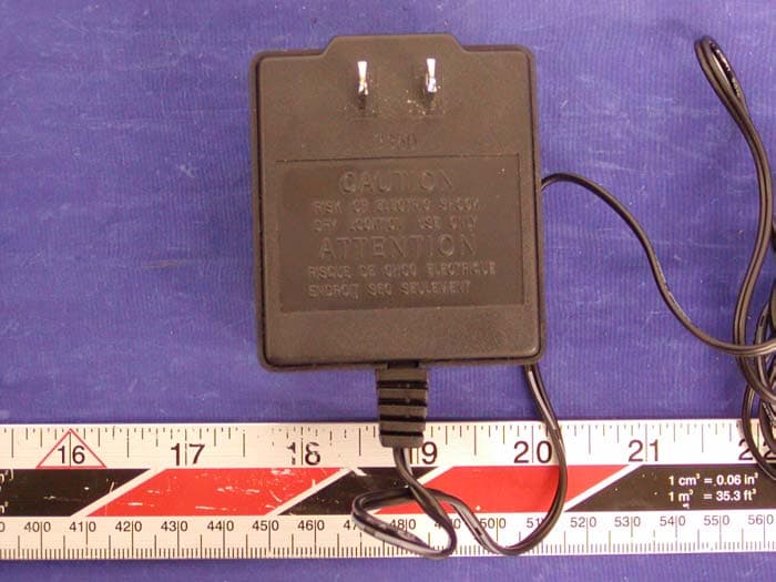
Click to zoom
Application Details
- Equipment Class
- DTS - Digital Transmission System
- Date of Grant
- Mar 09, 2004
- Application Purpose
- Original Equipment
- Date of Application
- Mar 09, 2004
- Equipment Note
- 802.11b Wireless ADSL Modem
- Frequency Range
- 2412.00000000 - 2462.00000000
- Country
- China
Documents & Files
Document Text
Text extracted from the exhibit documents filed with the FCC. Open a document above to read the original.
Users Manual
DB108-WL WIRELESS ADSL MODEM USER’S MANUAL (V3.0) DB108-WL wireless ADSL MODEM manual - 1 - CONTENTS 1 OVERVIEW ................................................................................................................................................. 3 1.1 ABOUT ADSL.......................................................................................................................................................................... 3 1.2 DEVICE INTRODUCTION.................................................................................................................................................... 3 1.3 PROTOCOLS............................................................................................................................................................................ 4 1.4 FEATURES............................................................................................................................................................................... 4 2 HARDWARE INSTALLATION AND BASIC CONFIGURATION............................................................ 5 2.1 SYSTEM REQUIREMENT....................................................................................................................................................... 5 2.2 HARDWARE INSTALLATION................................................................................................................................................. 5 2.2.1 BASIC CONNECTTION.................................................................................................................................................. 5 2.2.2 INSTALLATION STEPS.................................................................................................................................................. 5 2.3 SOFTWARE CONFIFURATION............................................................................................................................................... 6 2.3.1 PREPARATION BEFORE SOFTWARE INSTALLATION............................................................................................... 6 2.3.2 COMPUTER CONFIGURATION.................................................................................................................................... 6 2.3.3 WIRELESS ADSL MODEM CONFIGURATION................................................................................................... 6 2.3.4 ADSL MODEM WORK MODEL CONFIGURATION............................................................................................... 7 2.3.5 WIRELESS work model configuration..................................................................................7 2.3.6 DEFAULT CONFIGURATION ...................................................................................................................................... 9 3 PROTOCOL CONFIGURATION................................................................................................................. 10 3.1 RFC1483 BRIDGE CONFIGURTION................................................................................................................................. 10 3.2 STATI C ROUTING CONFIGURATION RFC1483ROUTING/RFC1577SETTING .............................................................. 11 3.3 PPPOA ANDPPPOE CONFIGURATION............................................................................................................................ 13 4 DHCP FUNCTION APPLICATION.....................................................................................16 4.1 TCP/IP PROTOCOL CONFIGURATION....................................................................................................................... 16 4.2 DB108-WL SETTINGS ............................................................................................................................................... 16 5 OTHER FUNCTIONS AND CONFIGURATION....................................................................................... 19 5.1 BRIDGE FILTERING............................................................................................................................................................. 19 5.2 STATUS BAR ......................................................................................................................................................................... 19 5.3 CONFIGURATION OF DB108-WL’S IP ADDRESS AND PASSWORD...................................................... 20 6 SOFTWARE UPGRADE................................................................................................................................22 7 RESET TO DEFAULT SETTING................................................................................................................. 22 8 SPECIFICATIONS......................................................................................................................................... 22 A TROUBLESHOOTING................................................................................................................................. 23 B CONNECTION OF SPLITTER................................................................................................................... 25 C SHIPPING LIST............................................................................................................................................. 26 DB108-WL wireless ADSL MODEM manual - 2 - 1. OVERVIEW 1.1 ABOUT ADSL An ADSL MODEM is a broadband Internet access device which utilizes the high frequency segment of the phone line to transmit high-speed data without affecting the voice transmission. The frequency of the ADSL signal is higher than that of voice, so voice and ADSL signal can coexist in one line by using a splitter to insulate each from the other. ADSL data transfer adapts the asymmetry model. It supports upload transmission speed up to 1Mbps and download speed up to 8 Mbps. ADSL is an ideal device for broadband access. But the ADSL …
Text truncated - open the document above for the full version.
Cover Letter(s)
——————————————————————————————————————— Federal Communications Commission Authorization and Evaluation Division Confidentiality Request regarding application for certification of FCC ID: RBNUT-300U Pursuant to Sections 0.457 and 0.459 of the Commission’s Rules, we hereby request confidential treatment of information accompanying this application as outlined below: Block Diagram, Schematic diagrams The above materials contain trade secrets and proprietary information not customarily released to the public. The public disclosure of these materials may be harmful to the applicant and provide unjustified benefits to its competitors. The applicant understands that pursuant to Section 0.457 of the Rules, disclosure of this application and all accompanying documentation will not be made before the date of the Grant for this application. Sincerely, Samuel Yang
External Photos
Shanghai Dare Technologies Co., Ltd FCC ID: RS3DB108-WL EXHIBIT C - EUT PHOTOGRAPHS EUT – Chassis Top View EUT – Chassis Bottom View Shanghai Dare Technologies Co., Ltd FCC ID: RS3DB108-WL EUT – Chassis Port View Power Adapter Top View Shanghai Dare Technologies Co., Ltd FCC ID: RS3DB108-WL Power Adapter Bottom View
ID Label/Location Info
EXHIBIT A - FCC ID LABEL INFORMATION Proposed FCC ID Label Specifications : Text is black or white in color and is left justified. Labels are silk-screened and shall be “permanently affixed” at a conspicuous location on the EUT. Proposed Label Location on EUT Bottom Side of EUT/FCC ID Label FCC ID: I38-NA8300-001 This device complies with Part 15 o the FCC Rules. Operation is subject to the following two conditions: (1) this device may not cause harmful interference, and (2) this device must accept any interference received, including interference that may cause undesired operation. 2.1875" 1.0" FCC ID: RS3DB108-WL
Internal Photos
Shanghai Dare Technologies Co., Ltd FCC ID: RS3DB108-WL EUT – Chassis Cover Off View EUT – Main Board Component View Shanghai Dare Technologies Co., Ltd FCC ID: RS3DB108-WL EUT – Main Board Solder View EUT – Daughter Board Component View Shanghai Dare Technologies Co., Ltd FCC ID: RS3DB108-WL EUT – Daughter Board Solder View EUT – Main Board + Daughter Board Component View I Shanghai Dare Technologies Co., Ltd FCC ID: RS3DB108-WL EUT – Component Shield Cover off View
Operational Description
Circuit Description a. Transmitter section Data from the host is sent to the U5(BBP/MAC ISL3871) through the PCMCIA interface. After being converted from digital to analog signals by the I and Q transmit digital-to-analog converters (DAC) in the U5(BBP/MAC ISL3871) the output signals are routed to the Transceiver ISL3684 (U11 pin46/47/49/50) . These balanced I and Q signals are fed through separate lowpass filters(R41/45/49/52 C100/105/107/108). The output of the LPFs are routed to the up converter in the U11 (Transceiver ISL3684), which translates the baseband signal to the 2.45GHz ISM band by mixing it, in a pair of balanced modulators, with the I and Q local oscillator signals derived from the external RF VCO(U15 pin10/11:ISL3084 see RF VCO section). After the LNA the signal proceeds to the quadrature up/down converter in the U11 (transceiver ISL3684), which performs direct down conversion to baseband. The local oscillator (LO) for the down conversion mixers is derived from the ISL3084 RF VCO (U15 pin10/11:ISL3084 see RF VCO section). The transmit output signal from the U11 pin23 is fed to the ISL3985 power amplifier (U12 pin12). After the RF PA the signal (U12 pin6) travels through a bandpass filter (FL4:BPF) and the Transmit/Receive (T/R) Switch(U8 pin1). The filter within the range of 2.4GHz ~2.5GHzh attenuates unwanted signals such as harmonics. The transmit output signal from the U8 pin5(Transmit/Receive Switch) is sent to the antenna1. b. Receiver section The input signal to the radio is received through either antenna1 or antenna2. The received signal from the selected antenna is fed to a bandpass filter (FL1:BPF) which prevents out-of-band interfering signals from altering the performance of the receiver. Then, the signal is routed to a low-noise amplifier (LNA) in the Transceiver ISL3684 (U11 pin17/18).The LNA is a fixed gain amplifier and is preceded by a 30dB attenuator. After the LNA the signal proceeds to the quadrature up/down converter in the U11 (transceiver ISL3684), which performs direct downconversion to baseband. The local oscillator (LO) for the down conversion mixers is derived from the ISL3084 RF VCO (U15 pin10/11:ISL3084 see RF VCO section). The baseband output signals are designated RxI+, RxI-, RxQ+ and RxQ-(U11 pin51/51/55/58). These analog differential outputs are fed through separate I and Q lowpass filters(R42/44/47/54 and C92/93/99/104) to the U5 pin76/77/79/80 (BBP/MAC ISL3871). After being converted from analog to digital signals by the I and Q transmit analog-to-digital converters (ADC) in the U5(BBP/MAC ISL3871) the output data is sent to the host through the PCMCIA interface. c. RF VCO section The RF VCO(ISL3084 U15) operates at twice the channel frequency. It is divided by two in a flip-flop circuit to form accurate in-phase (I) and quadrature (Q) LO signals at the channel frequency. The VCO is phase locked to the 44MHz crystal-controlled clock by the synthesizer in the U11 (transceiver ISL3684) and therefore constitutes an accurate channel frequency reference for the radio. The phase-locked loop (PLL) loop filter, consisting of C118,C123, R69, R65 and C125.
Operational Description
DB108-WL is a wireless ADSL Modemit integrates ADSLand wireless AP function together. It eliminate the cabling workloadwhen creating a LAN. It makes it possible for the user to access the internet even when in moving state.This device is especially suitable for the situation where cabling is inconvenient, such as hotel, coffee bar, airport, railway station and etc Specification Technique standard: • ANSI T1.413 Issue 2, ITU G.992.1 (G.dmt), G.992.2 (G.lite), G.994.1 (G.hs) • IEEE 802.11b • IEEE 802.3 IEEE 802.3uIEEE 802.1D • USB1.1 Protocols that supported: • RFC 2364 PPP over ATM AAL5 (PPPoA) • RFC 2516 PPP over Ethernet relay (PPPoE) • RFC 1483 LLC&VCMUX (Bridge and Router mode) • RFC 1577 Classical IP ARP over ATM Support ATM • ATM AAL5 UBR&CBR • 8 PVCs ATM Forum UNI3.1/4.0 OAM F4/F5 in compatible with I.610 • VPI/VCI Range: 0-2550-65536 Network Access standard: • IP Route Protocols : Static Routing and RIPv1, v2 • 802.1d Bridge protocol • DHCP server function can assign automatically IP addresses to client PC within the LAN. • DHCP Client function can get IP address from DHCP server. • DHCP Relay Proxy • NATmakes it possible for multiple client PC to share the same public IP address to access the internet. • Support IGMPIGMP Proxyfor video application • VPN Transparency • DNS Proxy • Virtual ServerDMZPPP on Half Bridge Management • Configuration on Web pages. • Hardware Reset to restore factory settings. • USB Driver support Win98, Win98SE, Win2k, WinME, WinXP Security • MAC Address filter • User Password Authentication • Support PAP/CHAP Authentication of PPP protocol • ESSID Function and 64/ 128bit WEP data encryption Wireless Working Frequency 2400 ~ 2483.5MHz ISM Data rate 11Mbps 5.5M bps 2M bps1Mbps Modulation DQPSK, DBPSK and CCK T ransmit Power15dBm Receive sensitivity Min. –84dBm for 11Mbps @ 8% PER Min. –87dBm for 5.5Mbps @ 8% PER Antenna Embedded non-directional antenna Roaming In compliance with IAPP standard LED display • Power, link( ADSL), PC, Data Port and Interface • LAN port: RJ-45 • WAN Port: RJ-11 • USB port: Using for firmware upgrading and for internet accessing. Power supply • External Power adapterInput22VAC50Hz5W Output11VDC700mA Size • 184mmlengthx145mmwidthx41mm height Weight • 271grams Environment requirement • Working temperature: 0°C–40°C, • Storage temperature: –10°C–70°C • Working humidity: 10–90% No condensing • Storage humidity: 5–95% No condensing Certification: • UL1950 3 rd Edition, FCC Part 15 Class B, FCC Part 68, CE Marked for EMC and Safety
Parts List/Tune Up Info
DB108--WL BOM ITEM DESCRIPTION MAP 1 GAS DISCHARGE TUBE 270V-350V RV1 2 CAP CHIP CER NPO 22pF 50V 5% 0603 C75-76 3 CAP CHIP CER NPO 33pF 50V 5% 0603 C112 4 CAP CHIP CER NPO 47pF 50V 5% 0603 C116 5CAP CHIP CER NPO 100pF 50V 5% 0603 C113 6 CAP CHIP CER NPO 470pF 50V 5% 0603 C3 C66-67 C111 C118 7 CAP CHIP CER X7R 1nF 25V 10% 0603C20 C40-44 C92 8CAP CHIP CER X7R 4.7pF 50V 10% 0603C114 9 CAP CHIP CER Y5V 1uF 16V 20% 1206C1 10CAP CHIP CER Y5V 100nF 50V 20% 0603 C2 C5 C9 C11 C13 C15 C18-19 C22-23 C25 C31-32 C35 C38 C46-58 C60-64 C69-71 C73-74 C77-79 C81 C90-91 C93-94 C98-102 C105 C110 C115 C117 11CAP CHIP CER X7R 100nF 16V 10% 0603 C27-28 12CAP CHIP CER X7R 2.2uF 16V 20% 1206 C39 C127 13CAP Y1 1nF 250Vac 10% P=5mm C45 14 CAP ALUM ELEC 470uF 16V 20% 8×12mm C7 15 CAP ALUM ELEC 22uF 25V 20% 5×7mm C6 C8 C12 C21 C24 C26 C34 C36-37 C59 C68 C80 16 CAP POLYESTER METAL FILM 27nF 63V 5% P=5mm C106-107 17 CAP POLYESTER METAL FILM 56nF 63V 5% P=5mm C124-125 18 CAP POLYESTER METAL FILM 68nF 63V 5% P=5mm C122-123 19 CAP POLYESTER METAL FILM 33nF 630V 10% P=10mmC126 20CRYSTAL 35.328MHz FUN 15pF HC49/UY1 21DIODE BAS16 SOT-23 D8-9 22CRYSTAL 25MHz FUN 18pF HC49/U Y2 23IC 74VHC14 TSSOP14 U10 24FERRITE BEAD 1K@100MHz 0805 L8 L10-13 25IC POWER AIC1563cn DIP8 U4 26IC 74AHC32 TSSOP14U11 27IC LOGIC NC7WZ04 SC70-6 U7 28 IC ADSL CX82310-14 FPBGA256U6 29 IC SDRAM MT48LC4M16A2_4MX16 TSOP-54U8 30 IC FLASH MXIC MX29LV160BTC-90 TSOP48 U5 31 REGULATER 1117-3.3V SOT223U1 32 IC PHY REALTEK RTL8201BL LQFP48U3 33 REGULATER 1117-3.3V SOT223U2 34 RES ARRAY CHIP 47 5% YC16 8Pin/4R RP1-8 35 RES CHIP 0 5% 1/4W 0805R18-19 R34 R37 36RES CHIP 0 5% 1/8W 0603R5 R16 R21 R47 R50 R53 R56 R59 R104 37RES CHIP 4.7 1% 1/8W 0805 R86 R90 38RES CHIP 1 1% 1/10W 0603R6-10 39RES CHIP 1K 5% 1/10W 0603R3-4 R13 R71 R111-112 40 RES CHIP 10K 5% 1/10W 0603 R1 R23-25 R29 R31-32 R41-42 R49 R78-79 R101 41RES CHIP 10 5% 1/10W 0603R54-55 42RES CHIP 1.5K 5% 1/10W 0603R58 43RES CHIP 150K 5% 1/10W 0603R83 44RES CHIP 20K 5% 1/10W 0603R72 45RES CHIP 270K 5% 1/10W 0603R15 46RES CHIP 24 5% 1/10W 0603R81 47RES CHIP 30K 5% 1/10W 0603R2 48RES CHIP 4.7K 5% 1/10W 0603R36 R51-52 49RES CHIP 51 5% 1/10W 0603R73-74 R82 50RES CHIP 124K 1% 1/10W 0603R20 51RES CHIP 130 1% 1/10W 0603R87-88 52RES CHIP 1.91K 1% 1/10W 0603R17 53RES CHIP 3K 1% 1/10W 0603R12 54RES CHIP 30.1K 1% 1/10W 0603R77 55RES CHIP 61.9 1% 1/10W 0603R89 R93 56RES CHIP 71.5 1% 1/10W 0603R96-97 57TRIODE NPN MMBT3904 SOT23Q4-6 61ADSL LINE TRANSFORM 1:3.3 TH-10T1 62TRANSFORM H1102TR1
RF Exposure Info
§1.1307(b)(1) & §2.1091 - RF EXPOSURE According to §15.247(b)(5) and §1.1307(b)(1), systems operating under the provisions of this section shall be operated in a manner that ensures that the public is not exposed to radio frequency energy level in excess of the Commission’s guidelines. According to §1.1310 and §2.1091 RF exposure is calculated. Limits for General Population/Uncontrolled Exposure Frequency Range (MHz) Electric Field Strength (V/m) Magnetic Field Strength (A/m) Power Density (mW/cm 2 ) Averaging Time (minute) Limits for General Population/Uncontrolled Exposure 0.3-1.34 614 1.63 *(100) 30 1.34-30 824/f 2.19/f *(180/f 2 ) 30 30-300 27.5 0.073 0.2 30 300-1500 / / f/1500 30 1500-100,000 / / 1.0 30 f = frequency in MHz * = Plane-wave equivalent power density MPE Prediction Predication of MPE limit at a given distance Equation from page 18 of OET Bulletin 65, Edition 97-01 S = PG/4πR² Where: S = power density P = power input to antenna G = power gain of the antenna in the direction of interest relative to an isotropic radiator R = distance to the center of radiation of the antenna Maximum peak output power at antenna input terminal: 16.93(dBm ) Maximum peak output power at antenna input terminal: 51.29 (mW) Prediction distance: 20 (cm) Predication frequency: 2400 (MHz) Antenna Gain (typical): 1.5 (dBi) antenna gain: 1.41 (numeric) Power density at predication frequency at 20 cm: 0.015(mW/cm 2 ) MPE limit for uncontrolled exposure at prediction frequency: 1.0 (mW/cm 2 ) Test Result The EUT is a mobile device. The power density level at 20 cm is 0.015 mW/cm², which is below the uncontrolled exposure limit of 1.0mW/cm² at 2400 MHz.
Test Report
Note: This test report is specially limited to the above client company and product model only. It may not be duplicated without prior written consent of Bay Area Compliance Laboratory Corporation. This report must not be used by the client to claim product endorsement by NVLAP or any agency of the U.S. Government. FCC PART 15 EMI MEASUREMENT AND TEST REPORT For Shanghai Dare Technologies Co., Ltd 22 F Shanghai Information Building No. 1555 KongJiang Road, Shanghai, China FCC ID: RS3DB108-WL 2004-02-21 This Report Concerns: Original Report Equipment Type: 802.11b Wireless ADSL Modem Test Engineer: Ming Jing Report No.: R0401155 Test Date: 2004-02-07 Reviewed By: Ling Zhang Prepared By: Bay Area Compliance Laboratory Corporation (BACL) 230 Commercial Street Sunnyvale, CA 94085 Tel: (408) 732-9162 Fax: (408) 732 9164 Shanghai Dare Technologies Co., Ltd FCC ID: RS3DB108-WL Report # R0401155Rpt Page 2 of 32 FCC Part 15.247 Test Report TABLE OF CONTENTS GENERAL INFORMATION.......................................................................................................................................4 PRODUCT DESCRIPTION FOR EQUIPMENT UNDER TEST (EUT) ....................................................................................4 OBJECTIVE...................................................................................................................................................................4 RELATED SUBMITTAL(S)/GRANT(S).............................................................................................................................4 TEST METHODOLOGY..................................................................................................................................................4 TEST FACILITY.............................................................................................................................................................4 LOCAL SUPPORT EQUIPMENT LIST AND DETAILS........................................................................................................5 EXTERNAL I/O CABLING LIST AND DETAILS...............................................................................................................5 SYSTEM TEST CONFIGURATION ..........................................................................................................................6 JUSTIFICATION.............................................................................................................................................................6 EUT EXERCISE SOFTWARE..........................................................................................................................................6 SPECIAL ACCESSORIES.................................................................................................................................................6 SCHEMATICS / BLOCK DIAGRAM.................................................................................................................................6 EQUIPMENT MODIFICATIONS.......................................................................................................................................6 CONFIGURATION OF TEST SYSTEM..............................................................................................................................7 TEST SETUP BLOCK DIAGRAM.....................................................................................................................................7 SUMMARY OF TEST RESULTS ...............................................................................................................................8 §15.203 - ANTENNA REQUIREMENT......................................................................................................................9 STANDARD APPLICABLE..............................................................................................................................................9 §15.207(A) - CONDUCTED EMISSIONS.................................................................................................................10 MEASUREMENT UNCERTAINTY..................................................................................................................................10 EUT SETUP................................................................................................................................................................10 SPECTRUM ANALYZER SETUP....................................................................................................................................10 TEST EQUIPMENT LIST AND DETAILS.........................................................................................................................10 TEST PROCEDURE......................................................................................................................................................10 SUMMARY OF TEST RESULTS.....................................................................................................................................11 CONDUCTED EMISSIONS TEST DATA.........................................................................................................................11 PLOT OF CONDUCTED EMISSIONS TEST DATA...........................................................................................................11 §15.209(A) - SPURIOUS EMISSION ........................................................................................................................14 STANDARD APPLICABLE............................................................................................................................................14 MEASUREMENT PROCEDURE......................................................................................................................................14 EQUIPMENT LISTS....................................................................................................................................…
Text truncated - open the document above for the full version.
Test Setup Photos
Shanghai Dare Technologies Co., Ltd FCC ID: RS3DB108-WL EXHIBIT B - TEST SETUP PHOTOGRAPHS Conducted Emission - Front View Conducted Emission - Side View Shanghai Dare Technologies Co., Ltd FCC ID: RS3DB108-WL Radiated Emission - Front View Radiated Emission - Rear View
Contact Information
Applicant
Yingui Zhai(Quality Supervisor)
Test Firm
Bay Area Compliance LaboratoryJohn Chan
Technical Specifications
| # | Rule Parts | Frequency Range | Power Output |
|---|---|---|---|
| 1 | 15C | 2.41 GHz - 2.46 GHz | 51.00 mW |
Other Applications from Shanghai DareGlobal Technologies Co., Ltd.
RS3IWI666
Feb 04, 2013802.11bgn Router
Equipment Class
DTS - Digital Transmission System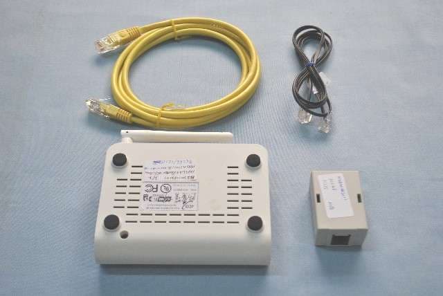
RS3PDGA2100NA
Feb 07, 2012ADSL2+ ROUTER WIFI 11n 1x1
Equipment Class
DTS - Digital Transmission System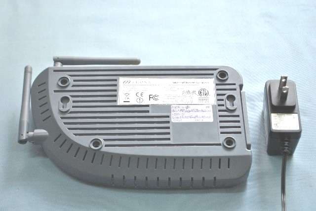
RS36519A1A2
Sep 01, 2011ADSL2+ 4 Port Router WIFI 802.11B/G/N 2X2
Equipment Class
DTS - Digital Transmission System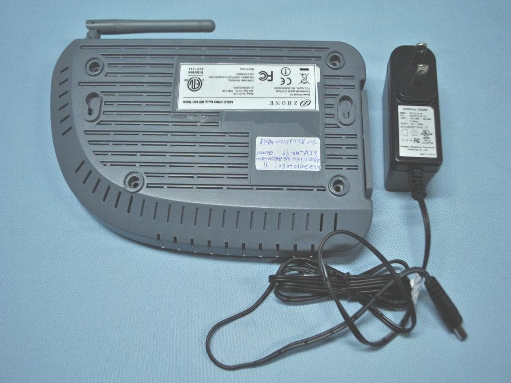
RS36518AX
Jul 13, 20114 PORT WIRELESS B/G ADSL2+ MODEM ROUTER
Equipment Class
DTS - Digital Transmission System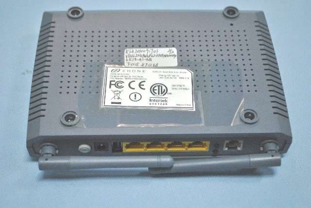
RS36519A1NA
Dec 16, 2010ADSL2+ 4PORT 802.11N ROUTER
Equipment Class
DTS - Digital Transmission System