RSFEG031EMNMicrowave Cooking Appliance
Guangdong Midea Kitchen Appliances Manufacturing Co.,Ltd.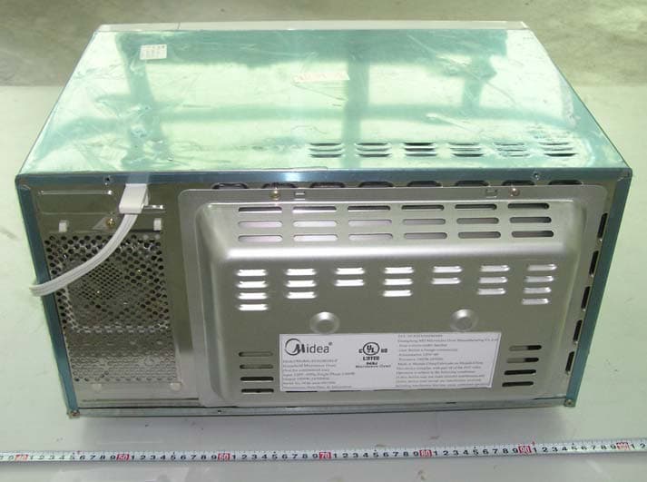
Click to zoom
Application Details
- Equipment Class
- 8CC - Part 18 Consumer Device
- Date of Grant
- Dec 01, 2005
- Application Purpose
- Original Equipment
- Date of Application
- Dec 01, 2005
- Equipment Note
- Microwave Cooking Appliance
- Frequency Range
- 2450.00000000 - 2450.00000000
- Country
- China
Documents & Files
Document Text
Text extracted from the exhibit documents filed with the FCC. Open a document above to read the original.
Users Manual
NOTE This device complies with part 18 of the FCC Rules. 1, Before commissioning this oven please read this instruction manual and keep it carefully. 2, There must be more than 30cm high space necessary above the top surface of oven. 3, Do not repair the oven yourself, please consult an authorized expert. 4, The contents of feeding bottles and bay food jars are to be stirred or shaken and the temperature is to be checked before consumption, in order to avoid burns. 5, Check the oven and the cable regularly for damage. If there is any kind of damage, the oven should not be used. Do not attempt to operate this oven with the door open since open- door operation can result in harmfulexposure to microwave energy. It is important not to defeat or tamper with the safety interlocks. Carefully clean door seala and sealing surfaces. Do not operate the oven if it is damaged. It is particularly important that the oven door close properly and that there is no damage to the : (1) door(bent). (2) hinges and latches( broken or loosened). (3) door seals and sealing surfaces. Utensils sould be checked to ensure that they are suitable for use in microwave ovens. When heating food in plastic or paper containers, check the oven frequently due to the possibility of ignition. Microwave heating of beverages can result in delayed eruptive boiling, therefore care has to be taken when handling the container. If smoke is observed, switch off or unplug the appliance and keep the door closed in order to stifle any flames. Egg in their shell and whole hard- bolled eggs shall not be heated in microwave ovens since they may explode. If the door or door seals are damaged. The oven must not be operated until it has been repaired by a trained person. Liquids or other foods must not be heated in sealed containers since they are liable to explode. Warning: 1, It is hazardous for anyone other than a trained person to carry out any service or repair operation, which involves the removal of any cover which gives protection against exposure to microwave energy. 2, Only allow children to use the oven without supervision when adequate instructions have been given so that the children is able to use the oven in a safe way and understands the hazards of improper use. 3, If the supply cord is damaged, it must be replaced by the manufacture of its service agent or a similarly qualified person in order to avoid a hazard. 4, This product will make disturbance in AV product, if any disturbance is occurred, use different electrical source jack to supply electricity or use low power or away from them. Note: THE MANUFACTURER IS NOT RESPONSIBLE FOR ANY RADIO OR TV INTERFERENCE CAUSED BY UNAUTHORIZATED MODIFICATIONS TO THIS EQUIPMENT .SUCH MODIFICATIONS COULD VOID THE USER’S AUTHORITY TO OPERATE THE EQUIPMENT.
Block Diagram
Cooling system (fan motor/blade/bracket) Power system(H. V. Transformer, H. V. Ca p acitor and H.V. diode ) Control system (PCB ) Microwave output Microwave generation system (Magnetron fre q uenc y 2450MHZ ) Microwave transfer system (wave-guide) Food cooking Turntable drive system (Turntable m o tor/tray/roller) Microwave resonance system (oven cavity) Lighting system Lam p /lam p holder Power suply 120V 60HZ/125V 60HZ EG 031E OH-P BLOCK DIAGRAM
External Photos
External Photos EUT-Front View EUT-Rear View
ID Label/Location Info
ID Label Label
ID Label/Location Info
ID Label/Location Label Location Information Specifications: Text is Black or white in color and is left justified. Labels are printed in indelible ink on permanent adhesive backing or silk-screened onto the EUT or shall be affixed at a conspicuous location on the EUT. Label Location
Internal Photos
Internal Photos EUT – Uncovered View (1) EUT – Uncovered View (2) EUT – Heater View EUT – Capacitor View EUT- Magnetron View EUT- Magnetron Label View EUT- Transformer View EUT- Transformer Label View EUT – Span View EUT – Control Unit View EUT – Control PCB Top View EUT – Control PCB Bottom View EUT – EMI Filter PCB Top View EUT – EMI Filter PCB Bottom View
Operational Description
When the microwave oven is plug into a wall outlet, the oven display “0:00”, Press “clock”, the LCD display 00:00, you can set the clock (You can press stop if you don’t want to set the clock). Then you can select cooking mode. There are several cooking modes, you can select power, auto cook, and auto defrosts, and so on. There is program in the Microcontroller of the control board, the cooking time and power level are pre-set in the program. Here we can choose the power level to cook food, so we can see how the microwave oven work. Put the food in the cavity glass tray, then press “power”, we can select one of ten power level (P100 to P10). We can select the difference power level by increasing the impulse ratio. The control of the power elements uses the keyboard commands. Then press “1-9”, we can set cooking time. As a final step, press “start”. (If you want to stop cooking, press “stop” or “pause”). Then magnetron power supply system will work, and High Voltage transformer, High Voltage diode, High Voltage capacitor will supply power to magnetron, and about 3 second the magnetron will work. The magnetron is a radio transmitter. . If it was on a radio mast it would be able to send radio signals a long way. But it is inside a metal box which keeps the signal in. The frequency of the transmitter is 2450MHz (megahertz), which is a wavelength of 12cm, rather than short waves, medium waves or long waves. In microwave cooking, the radio waves penetrate the food and excite water and fat molecules pretty much evenly throughout the food. Anything with water in it has all these molecules being moved this way and that by the electrical field, and heated up. Microwaves in this frequency range have another interesting property: they are not absorbed by most plastics, glass or ceramics. The dishes, walls of the oven , etc, don't pick up radio, so don't get heated up. The cooling system will start working, the lamp will be lighted, and the turntable will rotate, at the same time when the power supply system work. After we press “start”, the fan will running, it can get rid of its excess heat, and cooling the magnetron and High voltage transformer. You mustn't block the vents or the oven will overheat. At the same time, the turntable motor will turn. The turning system including the turntable motor, shaft, roller, and glass tray will start working.It is used for better cooking. An AC motor rotates the plate with constant speed about 5 rpm. When the start button is pushed the motor starts. A light that lights when the door is opened and when the oven is working. So we can see the food in cavity clearly! A ring alarm that makes a sound when cooking is done.
Schematics
1 2 3 4 5 6 78 ABCD 8 7 6 5 4 3 2 1 D CBA Title Number Revision Size A3 Date: 20-Oct-2005 Sheet of FilDDB Drawn By: BUZ1 R23 220 R20 220 R19 220 R18 220 R17 220 TR138050 R54 4.7K TR11 8050 R493.3K TR12 8050 R21 220 R25 220 R27 220 J RLY2 GRILL U J RLY3 MICRO D164148 R4720K R4447K VCC +12 R553.3k VCC L MOTOR D184148 D17 4148 J RLY1 D11 4148 TR88050 R421K +12 TR98550 +12 D124148 R434.7K TR108550 C110.1 μ F R464.7KR4010K VCC R48220 C3 10uF/16V R4110K R531K C2104 E1 1000U/25V TR78050 C5104 C4104 CC1 0.047uF/~250V +12 Z25V6 E2 1000U/16V E3 470U/16V 1 2 R9 390/1/4W ZR1 10D471 D2 4007 D9 4007 D104007 D34007 D44007D5 4007 D64007 D7 4007 123 CN1 POWER_SOCKT 1 345 2 6 T1PT-6329A PE2 1 PE3 2 PA2 4 T0 6 RESET 7 GND 8 PB0 9 PB1 10 PB2 11 PB3 12 PD0 13 PD1 14 PD2 15 PD3 16 PC0 17 PC1 18 PC2 19 PC3 20 VDD 21 OSCO 22 OSCI 23 PA0 24 PA1 25 PF0 26 PE0 27 PE1 28 PF1 3 PA3 5 IC1 SH69P25 CSA1 4MHz VCC DOOR1 R26 10K R24 10K R22 10K R28 10K VCC LED-1LED-2 LED-3 LED-4 ZERO RES RES VCC R452K C10 471 C60.1uF VCC C7104 E4 47uF/16V abcdef gdp LED-5 R13 1K R14 1K PB0PB1PB2PB3 R38 10K R39 10K PA3PA2 PB0PB1PB2PB3 PA1PA0 PD0PD1 5 4 3 2 13 12 11 10 9 8 7 6 1 led1 VCC R15 1K R16 1K R503.3K C1 471 R82K R72K Z14.7V D14148 VCC R11 1K R12 1K R563.3K PTC1 J RLY4 INRUSH TR148050 PD3 D194148 PD2PD3 SWD SWC R332K R352K VCC ZERO DIG1 DIG2 DIG3 DIG4 abcdef gdp DIG5 SWB SWA R292K R312K R37 10K R10 1K 1 2 3 4 5 6 7 8 9 10 11 12 CN2 LED-1LED-2LED-3LED-4 R34.7K TR3 8550 R54.7K TR68550 VCC R24.7K TR28550 R64.7K TR58550 LED-1 LED-2 LED-4 LED-3 R14.7K TR18550 LED-5 TR48550 R43.3K LED-1LED-2 LED-3 LED-4 PD0 PC0 R3020K R3420K R3620K R3220K PC0 PA0 D144148D154148D84148D134148 A0 1 A1 2 A2 3 Vss 4 SDA 5 SCL 6 WP 7 Vcc 8 IC224C02 VCC C12104/25V R5110K R5210K VCC C16101 C18101 C17101 C19101 C13 101 C15 101 C14 101
Schematics
L(IN)N(IN) L(OUT) N(OUT) FUSE C10.33uF/275V FILTER R1510K/1/2W C2222C3222
Test Setup Photos
Test Setup Photos Conducted Emission–Front View Conducted Emission–Side View Radiated Emission (30MHz to 1000MHz) - Front View Radiated Emission (30MHz to 1000MHz) - Rear View Radiated Emission (Above 1 GHz) - Front View Radiated Emission (Above 1 GHz) - Rear View
Contact Information
Applicant
Jilin Ye(Engineer)
Test Firm
Bay Area Compliance Laboratory Corp. (Shenzhen)John Chan
Technical Specifications
| # | Rule Parts | Frequency Range | Power Output |
|---|---|---|---|
| 1 | 18 | 2.45 GHz - 2.45 GHz | - |
Other Applications from Guangdong Midea Kitchen Appliances Manufacturing Co.,Ltd.
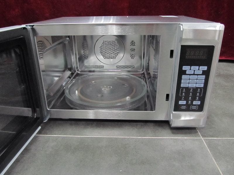
RSFXC032CYY
May 27, 2015Microwave Oven
Equipment Class
8CC - Part 18 Consumer Device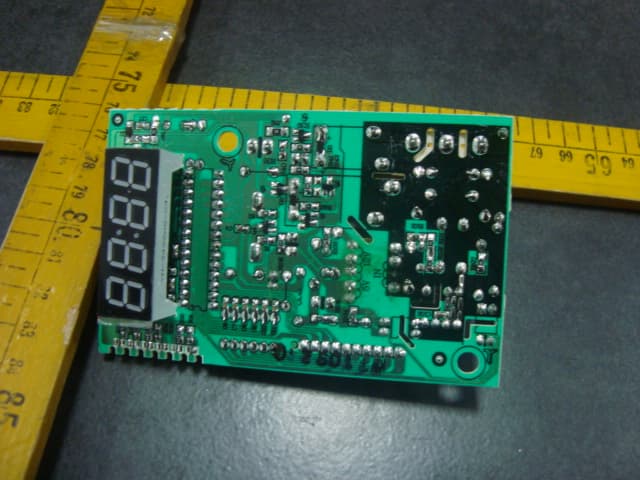
RSFXM131EYY
Feb 29, 2012Microwave Oven
Equipment Class
8CC - Part 18 Consumer Device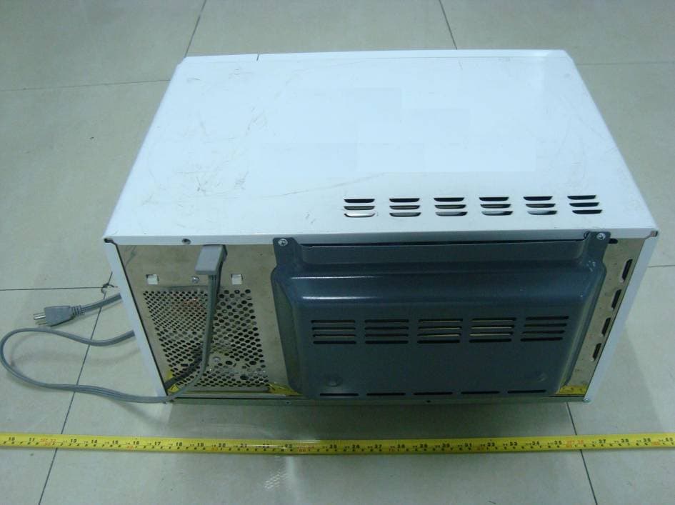
RSFXG925AYY
Jan 10, 2010Microwave Oven
Equipment Class
8CC - Part 18 Consumer Device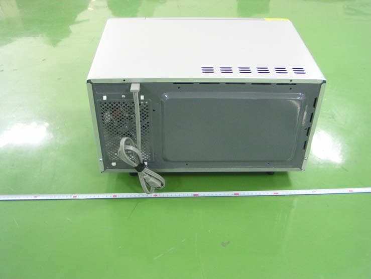
RSFEAM925FYY
Nov 11, 2007Microwave Oven
Equipment Class
8CC - Part 18 Consumer Device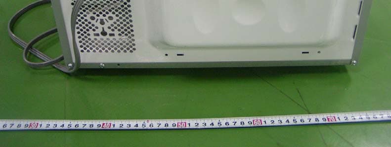
RSFEAM720CYY
Sep 12, 2007Microwave Oven
Equipment Class
8CC - Part 18 Consumer Device