RVZHYM360UHF RFID Reader Module
Winnix Technologies Co., Limited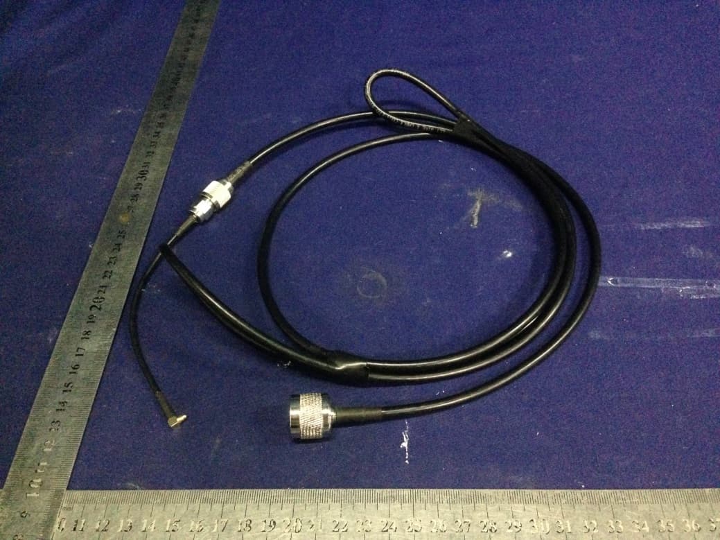
Click to zoom
Application Details
- Equipment Class
- DSS - Part 15 Spread Spectrum Transmitter
- Date of Grant
- Jun 29, 2015
- Application Purpose
- Original Equipment
- Date of Application
- Jun 28, 2015
- Equipment Note
- UHF RFID Reader Module
- Frequency Range
- 902.75000000 - 927.25000000
- Country
- China
Documents & Files
Document Text
Text extracted from the exhibit documents filed with the FCC. Open a document above to read the original.
Users Manual
UHF RFID Reader Module UHF RFID Reader Module HYM360 Winnix Te c h n o l o g i e s Co., Limited UHF RFID Reader Module Brief Introduction HYM360 UHF Reader Module complied with EPC C1G2 Protocol, its working frequency is 902.75-927.25MHz, with standard 2dBi antenna, the reading distance can reach 2 meters. With low power consumption, simple power supply and interface circuit, a high-performance and cost-effective RFID system can be established. It is suitable for retail,access control, medical industry, food tracking, anti-counterfeit and so on, especially for small size hand-held UHF RFID reader. Technical Date No. Item Technical DateUnit Remark 1 Fixed Current ≤380 mA 25dBm 2 Standby Current ≤1 mA EN Pin Low Level 3 Frequency Range 902.75-927.25 MHz 4 Default Working Frequency Hopping Frequency MHz Frequency Interval 250KHz 5 Fixed Power 25 dBm Max 27dBm 6 Stepping Interval 1 dBm 10~25dBm adjustable by soft 7 Label Protocol EPC C1G2 /ISO18000-6C 8 Starting Time ≤50 ms 9 VSWR ≤1.5 10 Max Reading Range 2 m 2dBi Antenna Characteristics of DC Data Min Va l u e Ty p i c a l Va l u e Max Va l u e Unit Remark Voltage of Power 3.3 4.2 5 V DC Input High Level 2 3.3 3.5 V GPIO 2 - 5 V EN Input Low Level -0.5 0 0.5 V GPIO - - 0.18 V EN Output High Level 2.3 - 3.3 V GPIO Output Low Level 0 - 1 V GPIO Enable Current 2 5 25 uA V EN ≥2V UHF RFID Reader Module Requirement on Antenna Product Features Electrical Properties: It is a general antenna for UHF RFID applications with high gain and low VSWR. Mechanical Properties: The compact and artistic antenna is suitable for all kinds of severe environment for its dual waterproof design with Gasket and silicone and strengthening rib of shell. Performance Specifications Frequency Range:860MHz~960MHz Maximum VSWR: ≤1.3:1 Gain: > 9 dBi H side HPBW: 70° E side HPBW: 70° Polarization: Circular Polarization Relative humidity: 5%~95% Input Impedance: 50 Ω Antenna Connection: N-50KFD (Type N Female) Physical specifications Size: 258mm×258mm×56mm Weight: 0.91kg(without bracket) Material: Engineering Plastic ASA、Aluminums Color: Ivory-white Enclosure Rating: IP67 Operational Temperature: -40°C~+ 85°C Storage Temperature: -40°C~+ 85°C Figure 1. The photograph of the antenna UHF RFID Reader Module Installation guide HYN503 antenna can be installed on steal framed structure or bracket by own antenna bracket, and connect with reader with coaxial line. The antenna can be installed horizontally or vertically, it is decided by installation location, the angle can be adjusted after installation according to the real environment. Antenna bracket is an optional accessory, you can choose according to your special requirement. 1. Installation Dimension Figure 2 Dimension of the antenna 2. Installation Steps 2.1 Horizontal Installation Step 1:Use M6 screw, elastic washer and plain washer, to fix the L board on the antenna, please see Figure 3:. Figure 3 The structure for the Step 1 in the first case Step 2:Please use M6 screw, elastic washer and plain washer and “Dog tooth” to fix it on the horizontal and vertical bracket, please see Figure 4. 1 L board(Bracket) 2. M6 screw, elastic washer and plain washer UHF Antenna 1 M6 screw, elastic washer and plain h 2Dog tooth 3M6 U style screw bolt Figure 4. The structure for the Step 2 in the first case 2.2 Vertical Installation Step 1:Use M6 screw, elastic washer and plain washer, to fix the L board on the antenna, as shown in Figure 5. Figure 5 The structure for the Step 1 in the second case Step 2:Please use M6 screw, elastic washer and plain washer and “Dog tooth” to fix it on the horizontal and vertical bracket, as shown in Figure 6. 1 L board(Bracket) 2. M6 screw, elastic washer and plain washer UHF RFID Reader Module 6 / 9 Figure 6 The structure for the Step 2 in the second case 1 M6 screw, elastic washer and plain washer 2 Dog tooth 3 M6 U style screw bolt UHF RFID Reader Module 7 / 9 Appearance and Structure Drawing 1 Size of Reader Module Interface Definition PIN Signal Name Signal Direction Function/Compatibility Description 1~2 NC NC 3~6 GND - Module Connecting Ground 7 VDD Input Module Supplying power 8 EN Input Module Enabling, Highly Effective 9 GPIO Output 10 GPIO Output 11 UART_RX Input 12 UART_TX Output 13~16 GND - Module connecting ground 17 RFOUT Bidirection Module Radio frequency Input and output interface 18~24 GND - Module connecting ground UHF RFID Reader Module 8 / 9 Environment Requirement No. Item Technical Data Unit Remark 1 Wo r k i n g temperature -20~+70 °C 2 Storage temperature -40~+85 °C 3 Relative humidity 10%~90% RH Circuit for Reference Drawing 2 Circuit for reference Warning This device complies with Part 15 of the FCC Rules. Operation is subject to the following two conditions: (1) this device may not cause harmful interference, and (2) this device must accept any interference received, including interference that may cause undesired operation. changes or modifications not expressly approved by the party responsible for compliance could void the user's authority to operate the equipment. UHF RFID Reader Module 9 / 9 NOTE: This equipment has been tested and found to comply with the limits for a Class B digital device, pursuant to Part 15 of the FCC Rules. These limits are designed to provide reasonable protection against harmful interference in a residential installation. This equipment generates, uses and can radiate radio frequency energy and, if not installed and used in accordance with the instructions, may cause harmful interference to radio communications. However, there is no guarantee that interference will not occur in a particular installation. If this equipment does cause harmful interference to radio or television reception, which can be determined by turning the equipment off and on, the user is encouraged to try to correct the interference by one or more of the following measures: -- Reorient or relocate the receiving antenna. …
Text truncated - open the document above for the full version.
Cover Letter(s)
SCS-F18: Project and Product Certification Representative Authorization Letter Page 1 of 2 Rev 5.0 775 Montague Expressway Milpitas, CA 95035 Tel: 408-526-1188 Fax: 408-526-1088 Email: [email protected] Project and Product Certification Representative Authorization Letter Reason for Amendment (current / obsolete) Revision History Approved Date From To Initial Release (obsolete) 1.0 1.0 Nov-14-2006 Revised wording (obsolete) 1.0 2.0 Sept–25-2007 Updated company template (obsolete) 2.0 3.0 Jan-31-2012 Updated letter information (obsolete) 3.0 4.0 May-23-2014 Added FCC ID field (current) 4.0 5.0 Sept 16 2014 SCS-F18: Project and Product Certification Representative Authorization Letter Page 2 of 2 Rev 5.0 Winnix Technologies Co., Limited 2015-06-02 To: SIEMIC, INC. 775 Montague Expressway, Milpitas, CA 95035 USA Dear Sir/Madam, Re: Product Certification Representative Authorization Letter We, Winnix Technologies Co., Limited hereby authorize SIEMIC, Inc. to act as a Certification Body for certifying for the following project(s): UHF RFID Reader Module MODEL No.: HYM360 FCC ID: RVZHYM360 Sincerely, Victorica Lee/GM E-mail: [email protected] Phone: 0086 755 8602 8268 EXT.:8652 Fax: 0086 755 2601 2377 Address: 4/F R2-B Building, Hi-tech Park, NanShan District, Shenzhen, Guangdong, China
Cover Letter(s)
SCS-F19: Confidentiality Request Letter Page 1 of 2 Rev 4.0 775 Montague Expressway Milpitas, CA 95035 Tel: 408-526-1188 Fax: 408-526-1088 Email: [email protected] Confidentiality Request Letter Reason for Amendment (current / obsolete) Revision History Approved Date From To Initial Release (obsolete) 1.0 1.0 Nov-14-2006 Adding CFR 2.459 (obsolete) 1.0 2.0 August – 11 - 2008 Updated company template & Added text box (obsolete) 2.0 3.0 Jan-31-2012 Added IC confidentiality letter form (current) 3.0 4.0 March-26-2015 SCS-F19: Confidentiality Request Letter Page 2 of 2 Rev 4.0 Winnix Technologies Co., Limited 2015-06-02 To: Industry Canada Certification and Engineering Bureau P.O. Box 11490, Station H 3701 Carling Avenue (Building 94) Ottawa, Ontario K2H 8S2 Attention: Manager, Equipment Certification Subject: Permanent Confidentiality Request for FCC ID: RVZHYM360 We hereby request confidential treatment of information accompanying this application as outlined below: - block diagrams; - operational description; - schematic diagrams. The above materials contain trade secrets and proprietary information not customarily released to the public. The public disclosure of these materials may be harmful to the applicant and provide unjustified benefits to its competitors. Sincerely, Victorica Lee/GM E-mail: [email protected] Phone: 0086 755 8602 8268 EXT.:8652 Fax: 0086 755 2601 2377 Address: 4/F R2-B Building, Hi-tech Park, NanShan District, Shenzhen, Guangdong, China
Cover Letter(s)
SCS-F26 Modular Approval Letter Page 1 of 3 Rev 9.0 775 Montague Expressway Milpitas, CA 95035 Tel: 408-526-1188 Fax: 408-526-1088 Email: [email protected] Modular Approval Declaration Letter Reason for Amendment (current / obsolete) Revision History Approved Date From To Initial Release (Obsolete) 1.0 1.0 Dec-04-2006 Added IC Modular Letter (Obsolete) 1.0 2.0 Feb 16 2009 Add LMA and MA option (Obsolete) 2.0 3.0 April 14 2010 Revised per RSS Gen issue 3.0 (Obsolete) 3.0 4.0 Jan 12 2011 Removed Foot(2) (obsolete) 4.0 5.0 July 19 2011 Adding New note per KDB996369 D01 V01R03 (obsolete) 5.0 6.0 August 29 2011 Updated company template & Added text box (obsolete) 6.0 7.0 Jan-31-2012 Updated modular requirement (obsolete) 7.0 8.0 Sept 05 2014 Updated template to meet RSP 100 issue 10 (current) 8.0 9.0 Nov 20 2014 SCS-F26 Modular Approval Letter Page 2 of 3 Rev 9.0 SHENZHEN HELIXIONGDI TECHNOLOGY CO,.LTD (Date) 05-18-2015 (Product name) FCC ID : RVZHYM360 , is seeking FCC Authorization as a Single Modular transmitter / Single Limited Modular Approval (Please check one). The EUT meets the requirements for Single Modular approval / Single Limited Modular Approval (please check one) as detailed in FCC public Notice DA00-1407. Compliance to each of the requirements is described below : Questions are: * Please provide a detailed explanation if the answer is “No.” Item Modular requirement Yes No 1 The radio elements must have the radio frequency circuitry shielded. Physical components and tuning capacitor(s) may be located external to the shield, but must be on the module assembly; The equipment don’t have the radio frequency circuitry shielded 2 The module must have buffered modulation/data inputs to ensure that the device will comply with Part 15 requirements with any type of input signal; √ 3 The module must contain power supply regulation on the module; √ 4 The module must contain a permanently attached antenna, or contain a unique antenna connector, and be marketed and operated only with specific antenna(s), per Sections 15.203, 15.204(b), 15.204(c), 15.212(a), 2.929(b); √ 5 The module must demonstrate compliance in a stand-alone configuration; √ 6 The module must be labelled with its permanently affixed FCC ID label, or use an electronic display (See KDB Publication 784748 about labelling requirements); √ 7 The module must comply with all specific rules applicable to the transmitter including all the conditions provided in the integration instructions by the grantee; √ 8 The module must comply with RF exposure requirements √ Note: (1) LMA may be granted when one or more of the requirements in the table above cannot be demonstrated. LMA will also be issued in those instances where applicants can demonstrate that they will retain control over the final installation of the device, such that compliance of the end product is assured. In such cases, an operating condition on the LMA for the module must state that the module is only approved for use when installed in devices produced by a specific manufacturer. When LMA is sought, the application for equipment certification must specifically state how control of the end product into which the module will be installed, and will be maintained, such that full compliance of the end product is always ensured. (2) Please provide Clear and specific instructions describing the conditions, limitations and procedures for third-parties to use and/or integrate the module into a host device. (3) For non-Software Defined Radio transmitter modules where software is used to ensure compliance of the device, technical description of how such control is implemented to ensure prevention of third party modification must be provided (see KDB 594280). Note 1: Compliance of a module in its final configuration is the responsibility of the applicant. A host device will not be considered certified if the instructions regarding antenna configuration provided in the original description, of one or more separately certified modules it contains, were not followed. Example: A separately certified low-power transceiver module using Bluetooth technology which is housed in a desktop computer, laptop or peripheral does not require the overall system to be recertified, if the desktop computer, laptop or peripheral, as a stand-alone unit, complies with all applicable technical standards. SCS-F26 Modular Approval Letter Page 3 of 3 Rev 9.0 Victorica Lee/GM E-mail: [email protected] Phone: 0086 755 8602 8268 EXT.:8652 Fax: 0086 755 2601 2377 Address: 4/F R2-B Building, Hi-tech Park, NanShan District, Shenzhen, Guangdong, China
Cover Letter(s)
Winnix Technologies Co., Limited Equipment Name: UHF RFID Reader Module FCC ID: RVZHYM360 Model: HYM360 Hopping description: Divide the bandwidth from 902.75MHz to 927.25MHz to 50 frequency points, each bandwidth with 500KHz. The system selects 16 frequency points from 50 frequency points. The transmitting point is selected randomly, and shared the same priority. The max frequency hopping time is less than 400ms. Hopping Sequence: For example, for the hop pattern of 925.75, 924.25, 921.75, 919.25, 920.25, 917.25, 910.25, 916.75, 916.25, 913.25, 905.75, 912.75, 908.75, 910.25, 908.25, 904.75 The sequential hops is no any order can follow, is completely random. Sincerely, Victorica Lee/GM E-mail: [email protected] Phone: 0086 755 8602 8268 EXT.:8652 Fax: 0086 755 2601 2377 Address: 4/F R2-B Building, Hi-tech Park, NanShan District, Shenzhen, Guangdong, China
External Photos
Antenna
ID Label/Location Info
Location
RF Exposure Info
FCC ID : RVZHYM360 RF EXPOSURE EVALUATION According to FCC 1.1310: The criteria listed in the following table shall be used to evaluate the environment impact of human exposure to radio frequency(RF) Radiation as specified in §1.1307(b) Limits for Maximum Permissible Exposure (MPE) Frequency Range(MHz) Electric Field Strength(V/m) Magnetic Field Strength(A/m) Power Density(mW/cm 2 ) Average Time (A) Limits for Occupational/Control Exposures 300-1500 -- -- F/300 6 1500-100000 -- -- 5 6 (B) Limits for General Population/Uncontrol Exposures 300-1500 -- -- F/1500 6 1500-100000 -- -- 1 30 11.1 Friis transmission formula: Pd= (Pout*G)\ (4*pi*R 2 ) Where Pd= Power density in mW/cm 2 Pout=output power to antenna in mW G= Numeric gain of the antenna relative to isotropic antenna Pi=3.1416 R= distance between observation point and center of the radiator in cm Pd the limit of MPE, 1mW/cm 2 . If we know the maximum gain of the total power input to the antenna, through the calculation, we will know the distance where the MPE limit is reached. 11.2 Measurement Result Antenna gain: 9.0dBi Channel Channel Freq. (MHz) Measured power (dBm) Tune-up power (dBm) Max tune-up power (dBm) Antenna Gain Numeric Evaluation result (mW/cm2 ) Power density Limits (mW/cm2 ) 0 902.75 26.160 26.0±1 27.0 7.9433 0.7920 1.0 25 915.25 26.633 26.0±1 27.0 7.9433 0.7920 1.0 49 927.25 26.390 26.0±1 27.0 7.9433 0.7920 1.0
Test Report
TRF No.:FCC 15.247/A Page 1 of 46 Report No.: ES150410076E Ver.1.0 Shenzhen EMTEK Co.,Ltd. Building 69, Majialong Industry Zone, Nanshan District, Shenzhen,Guangdong,China www.emtek.com.cn Tel: +86-755-2695 4280 Fax: +86-755-2695 4282 Access to the World FCC 47 CFR PART 15 SUBPART C CERTIFICATION TEST REPORT For UHF RFID Reader Module MODEL No.: HYM360 FCC ID: RVZHYM360 Trademark: Winnix REPORT NO.: ES150410076E ISSUE DATE: May 25, 2015 Prepared for Winnix Technologies Co., Limited 4/F R2-B Building, Hi-tech Park, NanShan District, Shenzhen, Guangdong, China Prepared by SHENZHEN EMTEK CO., LTD. Bldg 69, Majialong Industry Zone, Nanshan District, Shenzhen, Guangdong, China TEL: 86-755-26954280 FAX: 86-755-26954282 TRF No.:FCC 15.247/A Page 2 of 46 Report No.: ES150410076E Ver.1.0 Shenzhen EMTEK Co.,Ltd. Building 69, Majialong Industry Zone, Nanshan District, Shenzhen,Guangdong,China www.emtek.com.cn Tel: +86-755-2695 4280 Fax: +86-755-2695 4282 Access to the World Table of Contents 1 TEST RESULT CERTIFICATION ............................................................................................................. 3 2 EUT TECHNICAL DESCRIPTION............................................................................................................ 4 3 SUMMARY OF TEST RESULT ................................................................................................................ 5 4 TEST METHODOLOGY ........................................................................................................................... 6 4.1 GENERAL DESCRIPTION OF APPLIED STANDARDS ................................................................ 6 4.2 MEASUREMENT EQUIPMENT USED .......................................................................................... 6 4.3 DESCRIPTION OF TEST MODES ................................................................................................. 6 5 FACILITIES AND ACCREDITATIONS ...................................................................................................... 8 5.1 FACILITIES .................................................................................................................................... 8 5.2 LABORATORY ACCREDITATIONS AND LISTINGS ..................................................................... 8 6 TEST SYSTEM UNCERTAINTY .............................................................................................................. 9 7 SETUP OF EQUIPMENT UNDER TEST ............................................................................................... 10 7.1 RADIO FREQUENCY TEST SETUP 1 ......................................................................................... 10 7.2 RADIO FREQUENCY TEST SETUP 2 ......................................................................................... 10 7.3 CONDUCTED EMISSION TEST SETUP ..................................................................................... 12 7.4 BLOCK DIAGRAM CONFIGURATION OF TEST SYSTEM ......................................................... 13 7.5 SUPPORT EQUIPMENT ............................................................................................................. 13 8 TEST REQUIREMENTS ........................................................................................................................ 14 8.1 20DB BANDWIDTH ..................................................................................................................... 14 8.2 CARRIER FREQUENCY SEPARATION ...................................................................................... 17 8.3 NUMBER OF HOPPING FREQUENCIES ................................................................................... 20 8.4 AVERAGE TIME OF OCCUPANCY (DWELL TIME) .................................................................... 22 8.5 MAXIMUM PEAK CONDUCTED OUTPUT POWER ................................................................... 24 8.6 CONDUCTED SUPRIOUS EMISSION ........................................................................................ 27 8.7 RADIATED SPURIOUS EMISSION ............................................................................................. 34 8.8 CONDUCTED EMISSION TEST .................................................................................................. 43 8.9 ANTENNA APPLICATION ............................................................................................................ 46 TRF No.:FCC 15.247/A Page 3 of 46 Report No.: ES150410076E Ver.1.0 Shenzhen EMTEK Co.,Ltd. Building 69, Majialong Industry Zone, Nanshan District, Shenzhen,Guangdong,China www.emtek.com.cn Tel: +86-755-2695 4280 Fax: +86-755-2695 4282 Access to the World 1 TEST RESULT CERTIFICATION Applicant: Winnix Technologies Co., Limited 4/F R2-B Building, Hi-tech Park, NanShan District, Shenzhen, Guangdong, China Manufacturer: Winnix Technologies Co., Limited 4/F R2-B Building, Hi-tech Park, NanShan District, Shenzhen, Guangdong, China Product Description: UHF RFID Reader Module Model Number: HYM360 File Number: ES150410076E Date of Test: May 10, 2015 or May 25, 2015 Measurement Procedure Used: APPLICABLE STANDARDS STANDARD TEST RESULT FCC 47 CFR Part 2, Subpart J FCC 47 CFR Part 15, Subpart C PASS The above equipment was tested by SHENZHEN EMTEK CO., LTD. The test data, data evaluation, test procedures, and equipment configurations shown in this report were made in accordance with the procedures given in ANSI C63.10 (2013) and the energy emitted by the sample EUT tested as described in this report is in compliance with the requirements of FCC Rules Part 2 and Part 15.247 The test results of this report relate only to the tested sample identified in this report Date of Test : May 10, 2015 or May 25, 2015 Prepared by : Joe Xia /Editor Reviewer : Jack Li /Supervisor Approve & Authorized Signer : Lisa Wang/Manager TRF No.:FCC 15.247/A Page 4 of 46 Report No.: ES150410076E Ver.1.0 Shenzhen EMTEK Co.,Ltd.…
Text truncated - open the document above for the full version.
Test Setup Photos
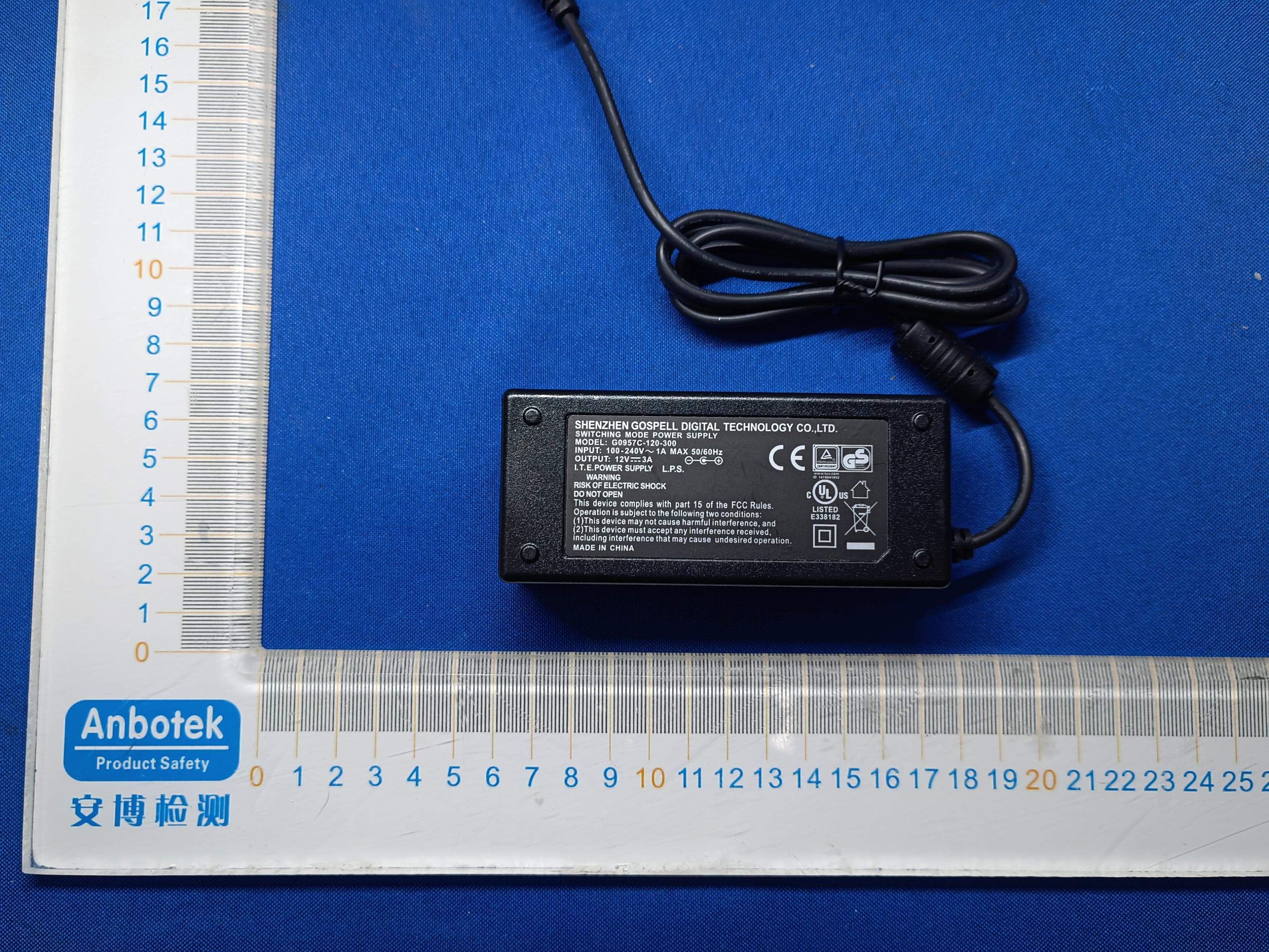
CONDUCTED SUPRIOUS EMISSION RADIATED SPURIOUS EMISSION
Contact Information
Applicant
Victorica Lee(GM)
Test Firm
EMTEK (Shenzhen) Co., Ltd.David Lee
Technical Specifications
| # | Rule Parts | Frequency Range | Power Output |
|---|---|---|---|
| 1 | 15C | 902.75 MHz - 927.25 MHz | 460.60 mW |
Other Applications from Winnix Technologies Co., Limited
RVZ-HYR860
Jan 16, 2023Integrated UHF RFID Reader
Equipment Class
DSS - Part 15 Spread Spectrum Transmitter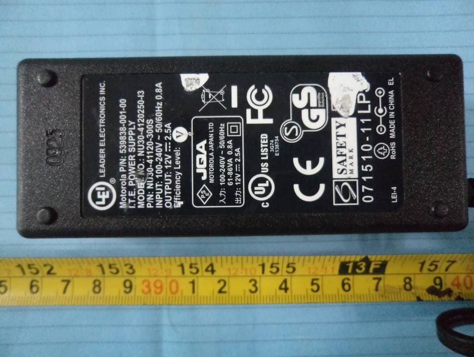
RVZHYR830
Jan 13, 2014UHF Reader
Equipment Class
DSS - Part 15 Spread Spectrum Transmitter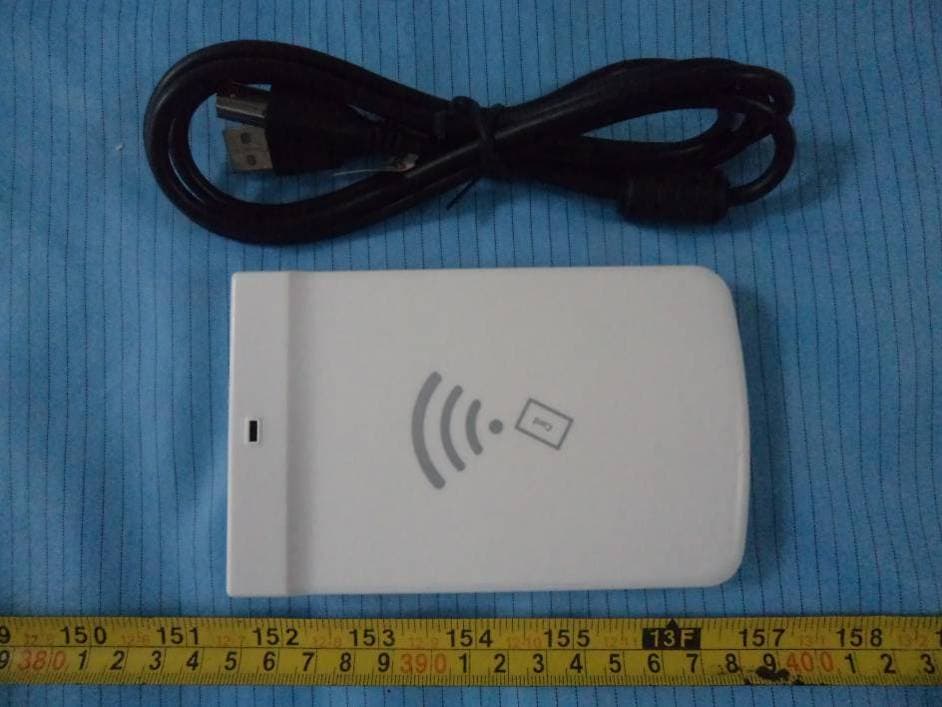
RVZHYR810
Jan 04, 2014UHF Desktop Reader
Equipment Class
DSS - Part 15 Spread Spectrum Transmitter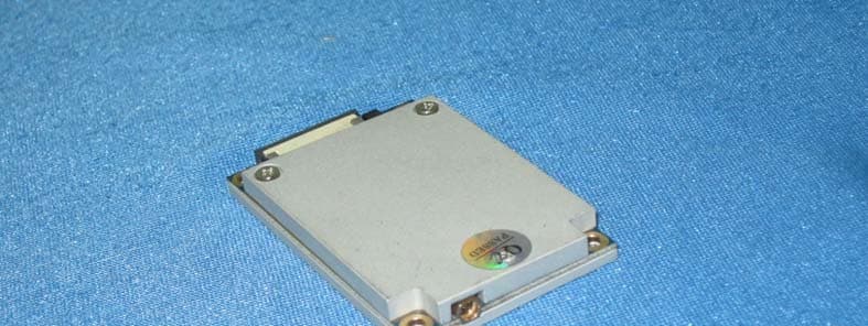
RVZHYM730
Dec 03, 2013UHF RFID Reader Module
Equipment Class
DSS - Part 15 Spread Spectrum Transmitter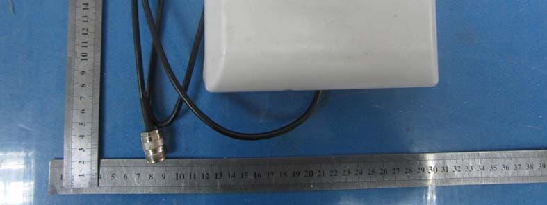
RVZHYM740
Nov 06, 2013UHF RFID Reader Module
Equipment Class
DSS - Part 15 Spread Spectrum Transmitter