RVZHYM730UHF RFID Reader Module
Winnix Technologies Co., Limited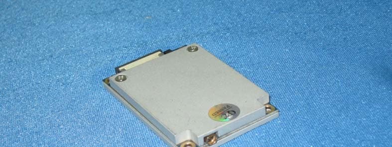
Click to zoom
Application Details
- Equipment Class
- DSS - Part 15 Spread Spectrum Transmitter
- Date of Grant
- Dec 03, 2013
- Application Purpose
- Original Equipment
- Date of Application
- Dec 03, 2013
- Equipment Note
- UHF RFID Reader Module
- Frequency Range
- 902.75000000 - 927.25000000
- Country
- China
Documents & Files
Document Text
Text extracted from the exhibit documents filed with the FCC. Open a document above to read the original.
Users Manual
UHF RFID Reader/Reader Module DEMO Software User Manual V1.1 Winnix Technologies Co., Limited www.winnix.net 2 Content Content................................................................................................................................2 1. Introduce.......................................................................................................................3 2. User Guide....................................................................................................................3 2.1 Language...........................................................................................................3 2.2 Connection.........................................................................................................4 2.1.1 Ethernet connection.................................................................................4 2.1.2 RS232 connection......................................................................................4 2.3 Single inventory operation...............................................................................5 2.4 Multiple inventory operation...........................................................................6 2.5 RF output power setting...................................................................................7 2.6 Region setting.....................................................................................................7 2.7 Frequency hopping setting...............................................................................8 2.8 Version info.........................................................................................................8 2.9 Temperature info...............................................................................................9 2.10 Recommended Link setting..............................................................................9 2.11 Antenna setting..................................................................................................9 2.12 Multiple inventory Delay time setting.............................................................9 2.13 Antenna working and interval time setting..................................................10 2.14 Buzzer setting....................................................................................................10 2.15 GPIO setting.......................................................................................................11 2.16 CW setting ..........................................................................................................11 2.17 RX ADC info.........................................................................................................11 2.18 Algorithm setting................................................................................................11 2.19 Single inventory timeout setting......................................................................12 2.20 Select and Query Setting...................................................................................12 2.21 Tag reading/writing setting...............................................................................12 2.22 Tag Lock setting...................................................................................................13 2.23 Tag Kill setting......................................................................................................14 2.24 FastID function.....................................................................................................14 2.25 TagFocus function................................................................................................15 www.winnix.net 3 1. Introduce The Demo software user manual is used for HYM730/HYM740/HYM750 serial modules and HYR810/HYR820/HYR830 series readers; Support Chinese and English language; Support RJ45 connecting. Adopt TCP long connection method, slave computer as TCP server, host computer demo software as the TCP client side. (Notice: RJ45 connecting only for HYR830 reader) Support RS232 connecting, baud rate 115200, 1 bit for start, 1 bit for stop, 8 bits for data. 2. User Guide 2.1 Language Two optional languages are supported: Simply Chinese English Open the DEMO software, as picture 1, click red marked area, could choose language. Picture 1 Opening interface www.winnix.net 4 2.2 Connection Demo software support two optional connecting, Ethernet and RS232 serial connections. 2.2.1 Ethernet connection setting Default IP address of the reader is 192.168.1.10. If connecting in Ethernet (RJ45), please set IP address of PC at same range, such as 192.168.1.100. Before connecting, make sure IP address of PC could be passed at Ping operation. Connections are displayed with different prefix. If connecting with RJ45, type ‘NET’+’IP’ at the drop-down box of port. For example, connect to 192.168.1.10, type ‘NET192.168.1.10’ as below picture. Picture 2 Ethernet port connection 2.2.2 RS232 connection Demo software could automatically display usable COM ports, click drop-down box, you will see below. Picture 3 Automatic identify serial port RS232 connection is with a prefix of ‘COM’, which user don’t need to input. What users have www.winnix.net 5 to do is to choose correct COM number, and then it should be connected, as below picture. Picture 4 RS232 port connection 2.3 Single inventory operation Single inventory operation is in ‘singe ask’ and ‘single answer’ method of reading. Each inventory will result an acknowledgement frame. In each single inventory, only one tag’s EPC data could be gotten. Single inventory mode supports to inventory tag function at any length EPC code. At workspace area, it could display EPC code, Inventory times, RSSI for each tag, as below picture. www.winnix.net 6 Picture 5 Single inventory mode 2.4 Multiple inventory operation Below picture is for multiple inventory mode. Inventory times are non-limited. At information area, it will display Inventory speed, time and tag numbers.…
Text truncated - open the document above for the full version.
Cover Letter(s)
Winnix Technologies Co., Limited. Winnix Technologies Co., Limited FCC ID:RVZHYM730 Data:Nov 18 th ,2013 Federal Communications Commission 7435 Oakland Mills Road Columbia, MD 21046 Gentlemen: This letter is to comply with Sections 0.457 and 0.459 pertaining to confidential material. Winnix Technologies Co., Limited would like the following documents regarding this submission for FCC ID: RVZHYM730 to be kept confidential. 1. Block Diagram 2. Schematic 3. Theory of Operation The above material contains trade secrets or technical data, which would customarily be guarded from competitors. We do not want these documents to be accessible to the general public. Sincerely, Victoria Lee/ GM Winnix Technologies Co., Limited Tel: 0755-86028268-8652 Fax: 0755-26012377 E-mail: [email protected]
Cover Letter(s)
Winnix Technologies Co., Limited. AUTHORIZATION LETTER FCC ID: RVZHYM730 Date: Sep 30, 2013 To whom it may concern: We the undersigned, hereby declares that 1. Marketing The device must be sold to dealers. 2. Professional installation Installed by licensed professionals ( EUT sold to dealer who hire installers) 3. Application The intended use is generally not for the general public. It is generally for industry/commercial use. If you have any questions regarding the authorization, please don’t hesitate to contact us. Sincerely, Victoria Lee/ GM Winnix Technologies Co., Limited Tel: 0755-86028268-8652 Fax: 0755-26012377 E-mail: [email protected]
Cover Letter(s)
Winnix Technologies Co., Limited. Oct 28,2013 Request for Limited Single Modular Approval Attestation for the Module (FCC ID: RVZHYM730) (i) The radio elements of the modular transmitter must have their own shielding. The physical crystal and tuning capacitors may be located ex‐ternal to the shielded radio elements. Yes, The modular transmitter has its own shielding as shown on the external photo exhibits. (ii) The modular transmitter must have buffered modulation/data inputs (if such inputs are provided) to ensure that the module will comply with part 15 requirements under conditions of ex‐cessive data rates or over‐modulation. Yes, All input/output data are buffered and processed by the onboard miccontroller. (iii) The modular transmitter must have its own power supply regulation. Yes,The modular with DC 5.0 regulation power supply; (iv) The modular transmitter must comply with the antenna and transmission system requirements of §§15.203, 15.204(b) and 15.204(c). The antenna must either be permanently attached or employ a ‘‘unique’’ antenna coupler (at all connections between the module and the antenna, including the cable). The ‘‘professional installation’’ provision of §15.203 is not applicable to modules but can apply to limited modular approvals under paragraph (b) of this section. No,The modular transmitter hasn’t antenna. We used an external antenna provided by Winnix, Technologies Co., Limited. There are related information about test antenna in the report. (v) The modular transmitter must be tested in a stand‐alone configuration, i.e., the module must not be inside an‐other device during testing for compliance with part 15 requirements. Unless the transmitter module will be battery powered, it must comply with the AC line conducted requirements found in §15.207. AC or DC power lines and data input/output lines connected to the module must not contain ferrites, un‐less they will be marketed with the module (see §15.27(a)). The length of these lines shall be the length typical of actual use or, if that length is unknown, at least 10 centimeters to insure that there is no coupling between the case of the module and supporting equipment. Any accessories, peripherals, or support equipment connected to the module during testing shall be unmodified and commercially available. Yes, The modular transmitter has been performed the testing as a stand alone and then confirmed the compliance. (vi) The modular transmitter must be equipped with either a permanently affixed label or must be capable of electronically displaying its FCC identification number. (A) If using a permanently affixed label, the modular transmitter must be labeled with its own FCC identification number, and, if the FCC identification number is not visible when the module is installed inside another device, then the outside of the device into which the module is installed must also display a label referring to the enclosed module. This exterior label can use wording such as the following: ‘‘Contains Trans‐mitter Module FCC ID: XYZMODEL1’’ or ‘‘Contains FCC ID: XYZMODEL1.’’ Any similar wording that expresses Winnix Technologies Co., Limited. the same meaning may be used. The Grant‐ee may either provide such a label, an example of which must be included in the application for equipment author‐ization, or, must provide adequate in‐structions along with the module which explain this requirement. In the latter case, a copy of these instructions must be included in the application for equipment authorization. (B) If the modular transmitter uses an electronic display of the FCC identi‐fication number, the information must be readily accessible and visible on the modular transmitter or on the device in which it is installed. If the module is installed inside another device, then the outside of the device into which the module is installed must displaya label referring to the enclosed module. This exterior label can use wording such as the following: ‘‘Contains FCC certified transmitter module(s).’’ Any similar wording that expresses the same meaning may be used. The user manual must include instructions on how to access the electronic display. A copy of these instructions must be in‐cluded in the application for equipment authorization. Yes,the modular with own FCC ID: RVZHYM730 will be labeled onto the modular transmitter. (vii) The modular transmitter must comply with any specific rules or operating requirements that ordinarily apply to a complete transmitter and the manufacturer must provide adequate instructions along with the module to explain any such requirements. A copy of these instructions must be included in the application for equipment authorization. Yes, The modular transmitter is compliant with part 15.247. Installation and other requirements are presented in the manual . (viii) The modular transmitter is compliant with part 15.247. Installation and other requirements are presented in the manual . Yes, The modular transmitter is compliant with part 15.247. Installation and other requirements are presented in the manual . Sincerely, Victoria Lee Title: GM Winnix Technologies Co., Limited Tel: 0755‐86028268‐8652 Fax: 0755‐26012377 E‐mail: [email protected]
External Photos
External Photos of The EUT
ID Label/Location Info
FCC ID:RVZHYM730
Internal Photos
Internal photos of the EUT
Test Report
FCC PART 15 SUBPART C TEST REPORT FCC PART 15.247 Report Reference No. .....................: FCC ID . ............................................: TRE1309009701 R/C:82060 RVZHYM730 Compiled by ( position+printed name+signature) .. : File administrators Jerome Luo Supervised by ( position+printed name+signature) .. : Test Engineer Yuchao Wang Approved by ( position+printed name+signature) .. : Manager Wenliang Li Date of issue ..................................... : Nov 28, 2013 Testing Laboratory Name .............. : Shenzhen Huatongwei International Inspection Co., Ltd Address ............................................ : Keji Nan No.12 Road, Hi-tech Park, Shenzhen, China Applicant’s name ............................ : Winnix Technologies Co., Limited Address ............................................ : 4/F R2-B Building,Hi-tech Park,NanShan District,ShenZhen, GuangDong,China Test specification: Standard ........................................... : FCC Part 15.247: Operation within the bands 902-928 MHz, 2400-2483.5 MHz and 5725-5850 MHz Direct Sequence System TRF Originator .................................. : Shenzhen Huatongwei International Inspection CO., Ltd Master TRF ....................................... : Dated 2006-06 Shenzhen Huatongwei International Inspection Co., Ltd. All rights reserved. This publication may be reproduced in whole or in part for non-commercial purposes as long as the Shenzhen Huatongwei International Inspection Co., Ltd is acknowledged as copyright owner and source of the material. Shenzhen Huatongwei International Inspection Co., Ltd takes no responsibility for and will not assume liability for damages resulting from the reader's interpretation of the reproduced material due to its placement and context. Test item description ..................... : UHF RFID Reader Module Trade Mark ....................................... : / Model/Type reference ....................... : HYM730 Modulation ........................................ : GFSK Manufacturer ................................... : RealID technology Co.,LTD. Listed Models .................................. : / Ratings ............................................ : DC 5.0 V Operation Frequency ....................... : From 902.75MHz to 927.25MHz Result................................................ : PASS Report No.: TRE1309009701 Page 2 of 50 Issue Data:2013-11-28 T E S T R E P O R T Test Report No. : TRE1309009701 Nov 28, 2013 ______________________________________________________________________________________________ Date of issue Equipment under Test : UHF RFID Reader Module Model /Type : HYM730 Listed Models : / Applicant : Winnix Technologies Co., Limited. Address : 4/F R2-B Building,Hi-tech Park,NanShan District,ShenZhen, GuangDong,China Manufacturer : RealID technology Co.,LTD. Address : Unit04,7/F,Bright way tower,NO.33 Mong KOK Road,Kowlood,HK. Test Result PASS The test report merely corresponds to the test sample. It is not permitted to copy extracts of these test result without the written permission of the test laboratory. Report No.: TRE1309009701 Page 3 of 50 Issue Data:2013-11-28 Contents 1. TEST STANDARDS .................................................................. 4 2. SUMMARY ............................................................................. 5 2.1. General Remarks 5 2.2. Equipment Under Test 5 2.3. Short description of the Equipment under Test (EUT) 5 2.4. EUT operation mode 5 2.5. Related Submittal(s) / Grant (s) 6 2.6. Configuration of Test System 6 2.7. EUT configuration 6 2.8. Modifications 6 2.9. NOTE 7 3. TEST ENVIRONMENT ............................................................... 8 3.1. Address of the test laboratory 8 3.2. Test Facility 8 3.3. Environmental conditions 9 3.4. Test Description 9 3.5. Statement of the measurement uncertainty 9 3.6. Equipments Used during the Test 10 4. TEST CONDITIONS AND RESULTS ............................................ 11 4.1. AC Power Conducted Emission(Not Applicable) 11 4.2. Radiated Emission 12 4.3. Spurious RF CONDUCTED EMISSIONS 16 4.4. Maximum Peak Output Power 24 4.5. 20dB Bandwidth 27 4.6. Band Edge 30 4.7. Frequency Separation 31 4.8. Number of hopping frequency 34 4.9. Time Of Occupancy(Dwell Time) 35 4.10. Receiver spurious Emissions 42 4.11. Antenna Requirement 46 5. TEST SETUP PHOTOS OF THE EUT .......................................... 47 6. EXTERNAL AND INTERNAL PHOTOS OF THE EUT ....................... 48 Report No.: TRE1309009701 Page 4 of 50 Issue Data:2013-11-28 1. TEST STANDARDS The tests were performed according to following standards: FCC Rules Part 15.247: Frequency Hopping, Direct Spread Spectrum and Hybrid Systems that are in operation within the bands of 902-928 MHz, 2400-2483.5 MHz, and 5725-5850 MHz. ANSI C63.10-2009 : American National Standard for Testing Unlicensed Wireless Devices Report No.: TRE1309009701 Page 5 of 50 Issue Data:2013-11-28 2. SUMMARY 2.1. General Remarks Date of receipt of test sample : Sep 29,2013 Testing commenced on : Sep 29,2013 Testing concluded on : Nov 28, 2013 2.2. Equipment Under Test Power supply system utilised Power supply voltage : ○ 120V / 60 Hz ○ 115V / 60Hz ○ 12 V DC ○ 24 V DC ● Other (specified in blank below) DC 5.0V 2.3. Short description of the Equipment under Test (EUT) 902-928MHz (UHF RFID Reader Module (HYM730)), For more details, refer to the user’s manual of the EUT. 2.4. EUT operation mode The EUT has been tested under typical operating condition.The Applicant provides communication tools software to control the EUT for staying in continous transmitting and receiving mode for testing. There are 50 channels of EUT, and the test carried out at the lowest channel, middle channel and highest channel . Frequency Range: 902-928MHz Channel number: 50 channels Modulation type: GFSK Antenna: External Antenna Description of the test mode There are fifty channels provide to the EUT. Channel Frequency(MHz) Channel Frequency(MHz) 1 902.75 26 …
Text truncated - open the document above for the full version.
Test Setup Photos
Test Setup Photos of The EUT
Contact Information
Applicant
Victorica Lee(GM)
Test Firm
Shenzhen Huatongwei International Insp. Co., LtdMoffy Yu
Technical Specifications
| # | Rule Parts | Frequency Range | Power Output |
|---|---|---|---|
| 1 | 15C | 902.75 MHz - 927.25 MHz | 364.00 mW |
Other Applications from Winnix Technologies Co., Limited
RVZ-HYR860
Jan 16, 2023Integrated UHF RFID Reader
Equipment Class
DSS - Part 15 Spread Spectrum Transmitter
RVZHYM360
Jun 29, 2015UHF RFID Reader Module
Equipment Class
DSS - Part 15 Spread Spectrum Transmitter
RVZHYR830
Jan 13, 2014UHF Reader
Equipment Class
DSS - Part 15 Spread Spectrum Transmitter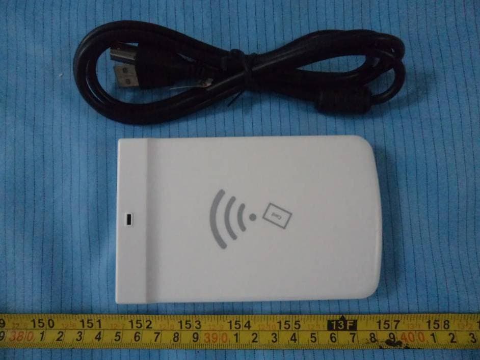
RVZHYR810
Jan 04, 2014UHF Desktop Reader
Equipment Class
DSS - Part 15 Spread Spectrum Transmitter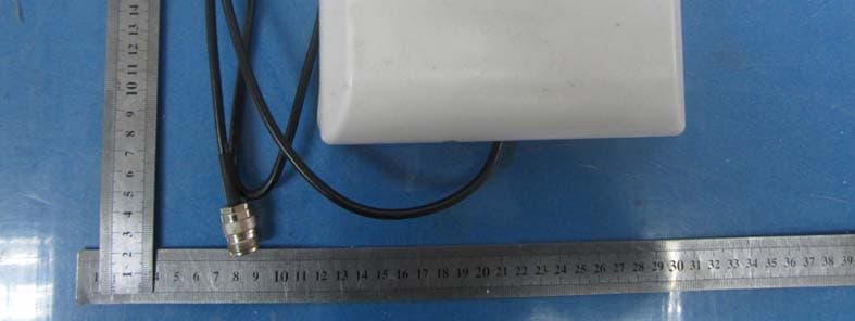
RVZHYM740
Nov 06, 2013UHF RFID Reader Module
Equipment Class
DSS - Part 15 Spread Spectrum Transmitter