RWO-RC30035302WModule
Razer Inc.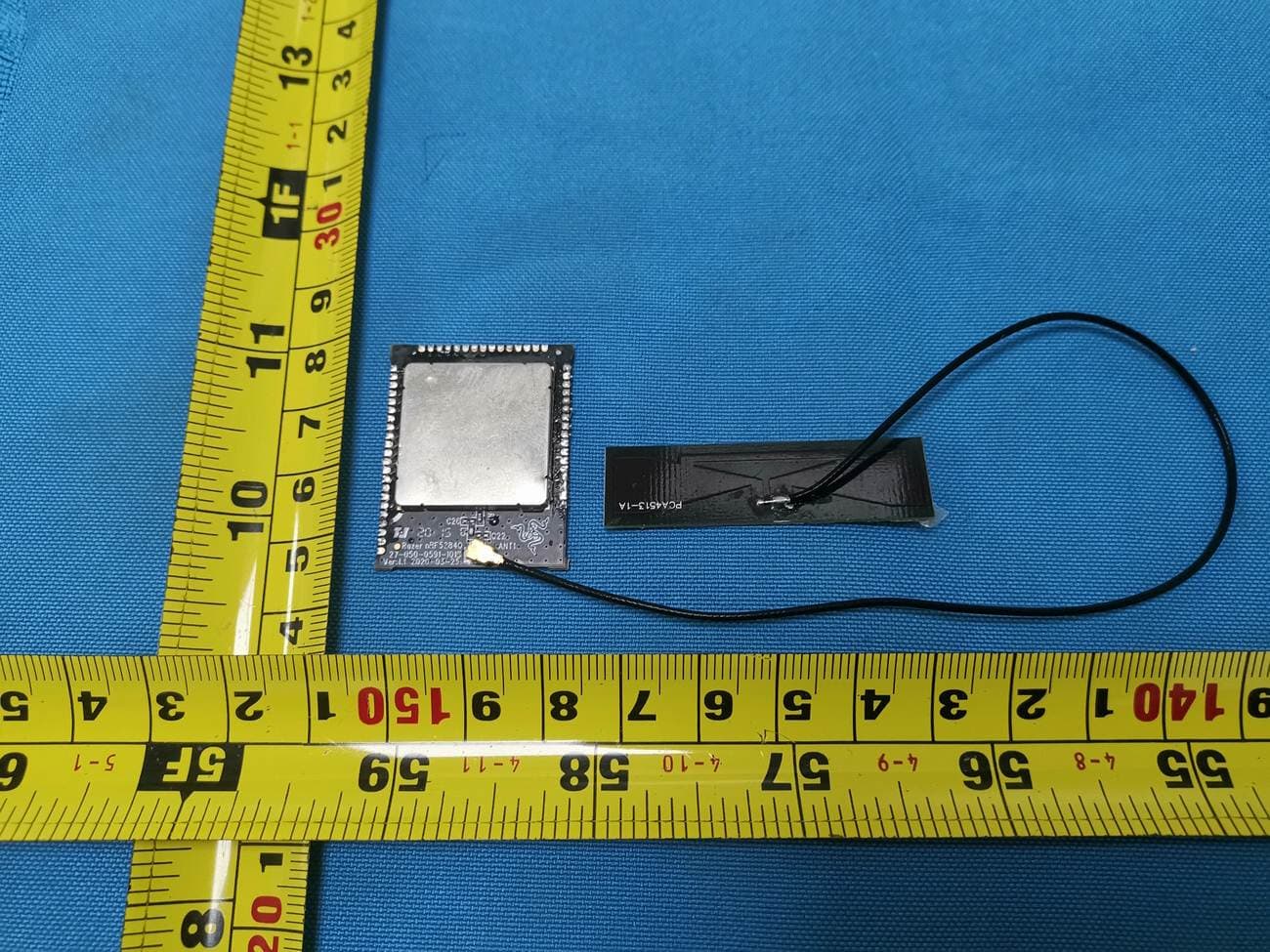
Click to zoom
Application Details
- Equipment Class
- DTS - Digital Transmission System
- Date of Grant
- Sep 14, 2020
- Application Purpose
- Original Equipment
- Date of Application
- Sep 08, 2020
- Equipment Note
- WModule
- Frequency Range
- 2402.00000000 - 2480.00000000
- Company
- Razer Inc.
- Country
- United States
Documents & Files
Document Text
Text extracted from the exhibit documents filed with the FCC. Open a document above to read the original.
Users Manual
Tech Specs for WModule Specifications Value Manufacturer Name 製造商名稱 Razer Inc. Manufacturing country (Full Address) 製造國(完整地址) 9 Pasteur, Suite 100, Irvine, CA92618, USA Product Name 品名 WModule Model Name 型號名稱 RC30-035302 Chipset 晶片組 nRF52840 (QIAA) Use (Specify: PMR, Amateur, Small Boats or other) Pl explain in detail the functionality 使用 2.4GHz and BLE Module Frequency/Frequency Range/BT/Lower power/Wifi? 頻率/頻率範圍/BT/低功率/Wifi? 2.4G/BLE - 2402MHz to 2480MHz RF Power output (EIRP) 射頻功率輸出(EIRP) BLE: 1Mbps 6dBm BLE: 2Mbps 6dBm 2.4GHz: 2Mbps 6dBm Modulation 調製 GFSK Channel Spacing: 頻道間距: BLE:2MHz 2.4GHz:1MHz Brand of Antenna 天線品 Walsin, RFPCA451321IMAB301 Antenna Type (Stubby Dipole): 天線類型 PCB Antenna PCB天線 Antenna Height 天線高度 on PCB Antenna Gain 天線增益 4.75dBi(max.) Product Picture 產品圖片 FCC Statement This device complies with Part 15 of the FCC Rules. Operation is subject to the following two conditions: (1) this device may not cause harmful interference, (2) this device must accept any interference received, including interference that may cause undesired operation. Any changes or modifications not expressly approved by the party responsible for compliance could void the user's authority to operate the equipment. Caution! Any changes or modifications not expressly approved by the party responsible for compliance could void the user's authority to operate the equipment. FCC Radiation Exposure Statement: The modular can be installed or integrated in mobile, portable or fix devices. This modular complies with FCC RF radiation exposure limits set forth for an uncontrolled environment. This transmitter must not be co-located or operating in conjunction with any other antenna or transmitter. If t he FCC identification number is not visible when the module is installed inside another device, then the outside of the device into which the module is installed must also display a label referring to the enclosed module. This exterior label can use wording such as the following: “Contains Transmitter Module FCC ID: RWO-RC30035302 or Contains FCC ID: RWO-RC30035302 ”. Th e devices must be installed and used in strict accordance with the manufacturer's instructions as described in the user documentation that comes with the product. When the module is installed inside another device, the user manual of this device must contain below warning statements: 1. This device complies with Part 15 of the FCC Rules. Operation is subject to the following two conditions: (1) This device may not cause harmful interference. (2) This device must accept any interference received, including interference that may cause undesired operation. 2. Changes or modifications not expressly approved by the party responsible for compliance could void the user's authority to operate the equipment. Federal Communication Commission Interference Statement This equipment has been tested and found to comply with the limits for a Class B digital device, pursuant to Part 15 of the FCC Rules. These limits are designed to provide reasonable protectio n against harmful interference in a residential installation. This equipment generates, uses and c an radiate radio frequency energy and, if not installed and used in accordance with the instruction s, may cause harmful interference to radio communications. However, there is no guarantee that interference will not occur in a particular installation. If this equipment does cause harmful interference to radio or television reception, which can be determined by turning the equipme nt off and on, the user is encouraged to try to correct the interference by one of the following measures: - Reorient or relocate the receiving antenna. - Increase the separation between the equipment and receiver. - Connect the equipment into an outlet on a circuit different from that to which the receiver is connected. - Consult the dealer or an experienced radio/TV technician for help. Canada Statement This device complies with Industry Canada’s licence-exempt RSSs. Operation is subject to the following two conditions: (1) this device may not cause interference, (2) this device must accept any interference, including interference that may cause undesired operation of the device. Le présent appareil est conforme aux CNR d'Industrie Canada applicables aux appareils radio exempts de licence. L'exploitation est autorisée aux deux conditions suivantes : (1) l'appareil ne doit pas produire de brouillage, et (2) l'utilisateur de l'appareil doit accepter tout brouillage radioélectrique subi, même si le brouillage est susceptible d'en compromettre le fonctionnement. Caution Exposure: This device meets the exemption from the routine evaluation limits in section 2.5 of RSS102 and users can obtain Canadian information on RF exposure and compliance. Le dispositif répond à l'exemption des limites d'évaluation de routine dans la section 2.5 de RSS102 et les utilisateurs peuvent obtenir des renseignements canadiens sur l'exposition aux RF et le respect. The final end product must be labelled in a visible area with the following: The Industry Canada certification label of a module shall be clearly visible at all times when installed in the host device, otherwise the host device must be labelled to display the Industry Canada certification number of the module, preceded by the words “Contains transmitter module”, or the word “Contains”, or similar wording expressing the same meaning, as follows: Contains transmitter module IC: 8092D-RC30035302 The module must be installed in WModule. The end user manual shall include all required regulatory information/warning as show in this manual. RF Specification RC30-035302 Module contains an integrated balun which provides a single-ended RF TX / RX IPEX connector. The transmitter has been optimised to deliver power in to a 50Ω load. And then,the RC30-035302 RF Spec base on N52840 DataSheet。 Bluetooth Transmitter Manual Information to the End User The OEM integrator has to be aware not to provide inform…
Text truncated - open the document above for the full version.
Cover Letter(s)
RF_160, Issue 02 Declaration of Authorization We Name: Razer Inc. Address: 9 Pasteur, Suite 100 City: Irvine State: California Country: United States Declare that: Name Representative of agent: Ms. Mandy Wang Agent Company name: BTL Inc. Address: No.3 Jinshagang 1st Road, Shixia, Dalang Town City: Dong Guan Country: China is authorized to apply for Certification and signing related documents of the following product(s), including 731 form(s): Product description: Wmodule Type designation: RC30-035302 Trademark: RAZER FCC ID : RWO-RC30035302 on our behalf. Date: 2020-07-20 City: San Francisco Name: Johnsen Tia Function: Senior Director, Regulatory & Compliance Signature: . Notes: (1): Required for FCC application (2): For FCC it must be the Grantee Code “owner” or the authorized agent.
Cover Letter(s)
FCC, Request for non-disclosure Date: 10-Aug-09 RF_501, Issue 5 Page 1 of 1 Company Name: Razer Inc. Address: 9 Pasteur, Suite 100 City: Irvine California Country: United States To: Telefication B.V., Dept. FCC TCB Edisonstraat 12A 6902 PK ZEVENAAR The Netherlands Subject: Request for confidentiality FCC ID: RWO-RC30035302 Reference number: ###### Dear FCC TCB, 1. Long-Term Confidentiality Pursuant to 47 CFR Section 0.459(a) & (b), we hereby requests non-disclosure and confidential treatment of the following materials submitted in support of FCC certification application: Bill(s) of Material Block Diagrams Operational Description Schematic Diagrams Tune-up Procedure Above materials contain secrets, proprietary and technical information, which would customarily be guarded from competitors under 47 CFR, section 0.457(d)(2). Disclosure or publication or any portion of this company confidential material to other parties could cause substantial competitive harm and provide unjustified benefits for competitors. 2. Short-Term Confidentiality (STC) Pursuant to Public Notice DA 04-1705 of the Commission’s policy, in order to comply with the marketing regulations in 47 CFR §2.803 and the importation rules in 47 CFR §2.1204, applicant hereby requests Short-Term Confidential treatment of the following materials (note 1): Internal Photos User’s Manual Test Set-up Photos External Photos Justification: This document contains detailed system and equipment description are considered as proprietary information in operation of the equipment. The public disclosure of above documents might be harmful to our company and would give competitor unfair advantage in the market. Planned Release Date STC: 180 days from date of grant (notes 2, 3, 4, 5) Date: 2020-07-20 Name and signature of applicant: Johnsen Tia Senior Director, Regulatory & Compliance Notes: 1) A document or type of document can only have ONE type of confidentiality! 2) Short-Term confidentiality is in principle for 45 days from date of grant; it can be extended max 3 times (total time 180 days max.)! 3) FCC must be informed when marketing begins earlier. 4) Release takes place automatically thus extension must be requested in time. Telefication does not remind you of this! FCC, Request for non-disclosure Date: 10-Aug-09 RF_501, Issue 5 Page 1 of 1 5) Request for extension or for release must be received by Telefication at least 7 days before date of actual marketing or before expiration of the STC period
Cover Letter(s)
RF_734_02 04 April 16 Modular Approval Request FCC (KDB 996369 D01 & Part 15.212) FCC ID: RWO-RC30035302 Items to be covered by Single modular transmitters. Answer from applicant 1.The modular transmitter must have its own RF shielding. YES, Please refer to External Photos. 2.The modular transmitter must have buffered modulation/data inputs (if such inputs are provided) to ensure that the module will comply with Part 15 requirements under conditions of excessive data rates or over-modulation. YES, U1 N52840 is used for the function. 3.The modular transmitter must have its own power supply regulation. NO 4.The modular transmitter must comply with the antenna requirements of Section 15.203 and 15.204(b)(c). The antenna must either be permanently attached or employ a “unique” antenna coupler (at all connections between the module and the antenna, including the cable). YES, it is PCB antenna. 5.The modular transmitter must be tested in a stand-alone configuration, i.e., the module must not be inside another device during testing. This is intended to demonstrate that the module is capable of complying with Part 15 emission limits regardless of the device into which it is eventually installed. Yes, the module is tested in a stand-alone configuration as the test photos show. 6.The modular transmitter must be equipped with either a permanently affixed label or must be capable of electronically displaying its FCC identification number in accordance with 15.212 (a)(1)(vi)(A) / (B). YES, please refer to the exhibition label sample for this module. 7.The modular transmitter must comply with any specific rule or operating requirements applicable to the transmitter and the manufacturer must provide adequate instructions along with the module to explain any such requirements. A copy of these instructions must be included in the application for equipment authorization. For example, there are very strict operational and timing requirements that must be met before a transmitter is authorized for operation under Section 15.231. For instance, data transmission is prohibited, except for operation under Section 15.231(e), in which case there are separate field strength level and timing requirements. Compliance with these requirements must be assured. YES, please refer to the user manual. 8.The modular transmitter must comply with any applicable RF exposure requirements. For example, FCC Rules in Sections 1.1310, 2.1091, 2.1093, and specific Sections of Part 15, including 15.319(i), 15.407(f), 15.253(f) and 15.255(g), require that Unlicensed PCS, UNII and millimeter wave devices perform routine environmental evaluation for RF Exposure to demonstrate compliance. In addition, spread spectrum transmitters operating under Section 15.247 are required to address RF Exposure compliance. Modular transmitters approved under other Sections of Part 15, when necessary, may also need to address certain RF Exposure concerns, typically by providing specific installation and operating instructions for users, installers and other interested parties to ensure compliance. YES, RF exposure statement is attached in the user manual. Note: A limited modular approval (LMA) may be granted for single or split modular transmitters that comply partially with the requirements above. Name and surname of applicant (or authorized representative): Johnsen Tia Date: 2020-07-20 Signature: ___________________________
External Photos
Report No.: 2005C131 Page 2 of 6
ID Label/Location Info
RC30-035302 Product Label Label is laser etch on the label area Label is laser etched on the label area Label Area
Internal Photos
Report No.: 2005C131 Page 3 of 6 Report No.: 2005C131 Page 4 of 6 Report No.: 2005C131 Page 5 of 6 Report No.: 2005C131 Page 6 of 6
RF Exposure Info
Report No.: BTL-FCCP-3-2005C131 Page 1 of 6 FCC RF EXPOSURE REPORT FCC ID: RWO-RC30035302 Project No. : 2005C131 Equipment : WModule Brand Name : RAZER Test Model : RC30-035302 Series Model : N/A Applicant : Razer Inc. Address : 9 Pasteur, Suite 100, Irvine, CA92618, USA. Manufacturer : Razer (Asia-Pacific) Pte.,Ltd. Address : 514 Chai Chee Lane, #07-01-06,Singapore 469029 Factory : RAZER TECHNOLOGY AND DEVELOPMENT (SHENZHEN) CO., LTD. Address : East Wing, 3rd Floor, Block 2, Phase 1 of Vision Shenzhen Business Park Keji South Road, Hi-Tech Industrial Park, Shenzhen 518057, China. Date of Receipt : May 25, 2020 Date of Test : Jun. 01, 2020 ~ Jun. 22, 2020 Issued Date : Aug. 28, 2020 Report Version : R00 Test Sample : Sample No.: DG20200526139 Standard(s) : FCC Guidelines for Human Exposure IEEE C95.1 & KDB447498 D01 The above equipment has been tested and found compliance with the requirement of the relative standards by BTL Inc. Prepared by : Welly Zhou Approved by : Ethan Ma Add: No.3, Jinshagang 1st Road, Shixia, Dalang Town,Dongguan, Guangdong, China. Te l : +86-769-8318-3000 Web: www.newbtl.com Report No.: BTL-FCCP-3-2005C131 Page 2 of 6 REPORT ISSUED HISTORY Report Version Description Issued Date R00 Original Issue. Aug. 28, 2020 Report No.: BTL-FCCP-3-2005C131 Page 3 of 6 1. GENERAL INFORMATION 1.1 GENERAL DESCRIPTION OF EUT Equipment WModule Brand Name RAZER Te s t Model RC30-035302 Series Model N/A Model Difference(s) N/A Power Source DC voltage supplied from external power supply. Power Rating DC 5V Product Description for LE Operation Frequency 2402 MHz ~ 2480 MHz Modulation Technology GFSK Bit Rate of Transmitter 1Mbps, 2Mbps Max. Output Power 3.84 dBm (0.0024 W) For 1Mbps 3.81 dBm (0.0024 W) For 2Mbps Product Description for 2.4G SRD Operation Frequency 2402 MHz ~ 2480 MHz Modulation Technology GFSK Bit Rate of Transmitter 2 Mbps Max. Output Power 3.85 dBm (0.0024 W) Note: 1. For a more detailed features description, please refer to the manufacturer’s specifications or the user's manual. 2. Channel List: For LE: Channel Frequency (MHz) Channel Frequency (MHz) 00 2402 20 2442 01 2404 21 2444 02 2406 22 2446 03 2408 23 2448 04 2410 24 2450 05 2412 25 2452 06 2414 26 2454 07 2416 27 2456 08 2418 28 2458 09 2420 29 2460 10 2422 30 2462 11 2424 31 2464 12 2426 32 2466 13 2428 33 2468 14 2430 34 2470 15 2432 35 2472 16 2434 36 2474 17 2436 37 2476 18 2438 38 2478 19 2440 39 2480 Report No.: BTL-FCCP-3-2005C131 Page 4 of 6 For 2.4G SRD: Channel Frequency (MHz) Channel Frequency (MHz) Channel Frequency (MHz) 00 2402 27 2429 54 2456 01 2403 28 2430 55 2457 02 2404 29 2431 56 2458 03 2405 30 2432 57 2459 04 2406 31 2433 58 2460 05 2407 32 2434 59 2461 06 2408 33 2435 60 2462 07 2409 34 2436 61 2463 08 2410 35 2437 62 2464 09 2411 36 2438 63 2465 10 2412 37 2439 64 2466 11 2413 38 2440 65 2467 12 2414 39 2441 66 2468 13 2415 40 2442 67 2469 14 2416 41 2443 68 2470 15 2417 42 2444 69 2471 16 2418 43 2445 70 2472 17 2419 44 2446 71 2473 18 2420 45 2447 72 2474 19 2421 46 2448 73 2475 20 2422 47 2449 74 2476 21 2423 48 2450 75 2477 22 2424 49 2451 76 2478 23 2425 50 2452 77 2479 24 2426 51 2453 78 2480 25 2427 52 2454 26 2428 53 2455 3. Table for Filed Antenna: LE / 2.4G SRD: Ant. Brand P/N Antenna Type Connector Gain (dBi) 1 PSA RFPCA371112IMAB301 PCB IPEX 4.75 Report No.: BTL-FCCP-3-2005C131 Page 5 of 6 2. GENERAL CONCULUSION According to FCC KDB447498 D01, Appendix A, SAR Test Exclusion Thresholds for 100 MHz – 6 GHz and ≤ 50 mm, the 1-g and 10-g SAR test exclusion thresholds are determined by the following: [(max. power of channel, including tune-up tolerance, mW) / (min. test separation distance, mm)] · [√f(GHz)] ≤ 3.0 for 1-g SAR, and ≤ 7.5 for 10-g extremity SAR, where f(GHz) is the RF channel transmit frequency in GHz Power and distance are rounded to the nearest mW and mm before calculation The result is rounded to one decimal place for comparison Appendix A - SAR Test Exclusion Thresholds for 100 MHz - 6 GHz and < 50 mm MHz 5 10 15 20 25 30 35 40 45 50 mm 150 39 77 116 155 194 232 271 310 349 387 SAR Test Exclusion Thresholds (mW) 300 27 55 82 110 137 164 192 219 246 274 450 22 45 67 89 112 134 157 179 201 224 835 16 33 49 66 82 98 115 131 148 164 900 16 32 47 63 79 95 111 126 142 158 1500 12 24 37 49 61 73 86 98 110 122 1900 11 22 33 44 54 65 76 87 98 109 2450 10 19 29 38 48 57 67 77 86 96 3600 8 16 24 32 40 47 55 63 71 79 5200 7 13 20 26 33 39 46 53 59 66 5400 6 13 19 26 32 39 45 52 58 65 5800 6 12 19 25 31 37 44 50 56 62 Report No.: BTL-FCCP-3-2005C131 Page 6 of 6 3. TEST RESULTS Tune up tolerance (dBm) LE 2.4G SRD ±1 ±1 For LE: Max. Output Power (dBm) Max. Output Power (mW) Limit (mW) 4.84 3.05 10 For 2.4G SRD: Max. Output Power (dBm) Max. Output Power (mW) Limit (mW) 4.85 3.05 10 Note: (1) Output power including tune up tolerance. (2) The maximum measured output peak power of this EUT is 3.05 mW, less than 10mW at 5mm distance. Conclusion: No SAR evaluation required since transmitter power is below FCC threshold. End of Test Report
Test Report
Report No.: BTL-FCCP-2-2005C131 Page 1 of 55 FCC Radio Test Report FCC ID: RWO-RC30035302 This report concerns: Original Grant Project No. : 2005C131 Equipment : WModule Brand Name : RAZER Test Model : RC30-035302 Series Model : N/A Applicant : Razer Inc. Address : 9 Pasteur, Suite 100, Irvine, CA92618, USA. Manufacturer : Razer (Asia-Pacific) Pte.,Ltd. Address : 514 Chai Chee Lane, #07-01-06,Singapore 469029 Factory : RAZER TECHNOLOGY AND DEVELOPMENT (SHENZHEN) CO., LTD. Address : East Wing, 3rd Floor, Block 2, Phase 1 of Vision Shenzhen Business Park Keji South Road, Hi-Tech Industrial Park, Shenzhen 518057, China. Date of Receipt : May 25, 2020 Date of Test : Jun. 01, 2020 ~ Jul. 30, 2020 Issued Date : Aug. 28, 2020 Report Version : R00 Test Sample : Sample No.: DG20200526139 Standard(s) : FCC Part15, Subpart C (15.247) ANSI C63.10-2013 FCC KDB 558074 D01 15.247 Meas Guidance V05r02 The above equipment has been tested and found compliance with the requirement of the relative standards by BTL Inc. Prepared by : Welly Zhou Approved by : Ethan Ma Add: No.3, Jinshagang 1st Road, Shixia, Dalang Town,Dongguan, Guangdong, China. Te l : +86-769-8318-3000 Web: www.newbtl.com Report No.: BTL-FCCP-2-2005C131 Page 2 of 55 Declaration BTL represents to the client that testing is done in accordance with standard procedures as applicable and that test instruments used has been calibrated with standards traceable to international standard(s) and/or national standard(s). BTL's reports apply only to the specific samples tested under conditions. It is manufacture’s responsibility to ensure that additional production units of this model are manufactured with the identical electrical and mechanical components. BTL shall have no liability for any declarations, inferences or generalizations drawn by the client or others from BTL issued reports. The report must not be used by the client to claim product certification, approval, or endorsement by NVLAP, NIST, A2LA, or any agency of the U.S. Government. This report is the confidential property of the client. As a mutual protection to the clients, the public and ourselves, the test report shall not be reproduced, except in full, without our written approval. BTL’s laboratory quality assurance procedures are in compliance with the ISO/IEC 17025 requirements, and accredited by the conformity assessment authorities listed in this test report. BTL is not responsible for the sampling stage, so the results only apply to the sample as received. The information, data and test plan are provided by manufacturer which may affect the validity of results, so it is manufacturer’s responsibility to ensure that the apparatus meets the essential requirements of applied standards and in all the possible configurations as representative of its intended use. Limitation For the use of the authority's logo is limited unless the Test Standard(s)/Scope(s)/Item(s) mentioned in this test report is (are) included in the conformity assessment authorities acceptance respective. Please note that the measurement uncertainty is provided for informational purpose only and are not use in determining the Pass/Fail results. Report No.: BTL-FCCP-2-2005C131 Page 3 of 55 Table of Contents Page REPORT ISSUED HISTORY 5 1 . SUMMARY OF TEST RESULTS 6 1.1 TEST FACILITY 7 1.2 MEASUREMENT UNCERTAINTY 7 1.3 TEST ENVIRONMENT CONDITIONS 7 2 . GENERAL INFORMATION 8 2.1 GENERAL DESCRIPTION OF EUT 8 2.2 DESCRIPTION OF TEST MODES 10 2.3 PARAMETERS OF TEST SOFTWARE 10 2.4 BLOCK DIAGRAM SHOWING THE CONFIGURATION OF SYSTEM TESTED 11 2.5 SUPPORT UNITS 11 3 . AC POWER LINE CONDUCTED EMISSIONS TEST 12 3.1 LIMIT 12 3.2 TEST PROCEDURE 12 3.3 DEVIATION FROM TEST STANDARD 12 3.4 TEST SETUP 13 3.5 EUT OPERATING CONDITIONS 13 3.6 TEST RESULTS 13 4 . RADIATED EMISSION TEST 14 4.1 LIMIT 14 4.2 TEST PROCEDURE 15 4.3 DEVIATION FROM TEST STANDARD 15 4.4 TEST SETUP 16 4.5 EUT OPERATING CONDITIONS 17 4.6 TEST RESULT - 9 KHZ TO 30 MHZ 17 4.7 TEST RESULT - 30 MHZ TO 1000 MHZ 17 4.8 TEST RESULT - ABOVE 1000 MHZ 17 5 . BANDWIDTH TEST 18 5.1 LIMIT 18 5.2 TEST PROCEDURE 18 5.3 DEVIATION FROM STANDARD 18 5.4 TEST SETUP 18 5.5 EUT OPERATION CONDITIONS 18 Report No.: BTL-FCCP-2-2005C131 Page 4 of 55 Table of Contents Page 5.6 TEST RESULTS 18 6 . MAXIMUM OUTPUT POWER 19 6.1 LIMIT 19 6.2 TEST PROCEDURE 19 6.3 DEVIATION FROM STANDARD 19 6.4 TEST SETUP 19 6.5 EUT OPERATION CONDITIONS 19 6.6 TEST RESULTS 19 7 . CONDUCTED SPURIOUS EMISSION 20 7.1 LIMIT 20 7.2 TEST PROCEDURE 20 7.3 DEVIATION FROM STANDARD 20 7.4 TEST SETUP 20 7.5 EUT OPERATION CONDITIONS 20 7.6 TEST RESULTS 20 8 . POWER SPECTRAL DENSITY TEST 21 8.1 LIMIT 21 8.2 TEST PROCEDURE 21 8.3 DEVIATION FROM STANDARD 21 8.4 TEST SETUP 21 8.5 EUT OPERATION CONDITIONS 21 8.6 TEST RESULTS 21 9 . MEASUREMENT INSTRUMENTS LIST 22 APPENDIX A - AC POWER LINE CONDUCTED EMISSIONS 24 APPENDIX B - RADIATED EMISSION - 9 KHZ TO 30 MHZ 27 APPENDIX C - RADIATED EMISSION - 30 MHZ TO 1000 MHZ 32 APPENDIX D - RADIATED EMISSION - ABOVE 1000 MHZ 35 APPENDIX E - BANDWIDTH 48 APPENDIX F - MAXIMUM OUTPUT POWER 50 APPENDIX G - CONDUCTED SPURIOUS EMISSION 52 APPENDIX H - POWER SPECTRAL DENSITY 54 Report No.: BTL-FCCP-2-2005C131 Page 5 of 55 REPORT ISSUED HISTORY Report Version Description Issued Date R00 Original Issue. Aug. 28, 2020 Report No.: BTL-FCCP-2-2005C131 Page 6 of 55 1. SUMMARY OF TEST RESULTS Test procedures according to the technical standard(s): FCC Part15, Subpart C (15.247) Standard(s) Section Test Item Test Result Judgment Remark 15.207 AC Power Line Conducted Emissions APPENDIX A PASS ------ 15.247(d) 15.205(a) 15.209(a) Radiated Emissions APPENDIX B APPENDIX C APPENDIX D PASS ------ 15.247(a)(2) Bandwidth APPENDIX E PASS ------ 15.247(b)(3) Maximum Output Power APPENDIX F PASS ------ 15.247(d) Conducted Spurious Emission APPENDIX G PASS ------ 15.247(e) Power Spectral Density APPENDIX H PASS ------ 15.203 Antenna Requirement ------ PASS Note(2) Note: (1) “N/A” denotes test is not applicable to this…
Text truncated - open the document above for the full version.
Test Report
Report No.: BTL-FCCP-1-2005C131 Page 1 of 70 FCC Radio Test Report FCC ID: RWO-RC30035302 This report concerns: Original Grant Project No. : 2005C131 Equipment : WModule Brand Name : RAZER Test Model : RC30-035302 Series Model : N/A Applicant : Razer Inc. Address : 9 Pasteur, Suite 100, Irvine, CA92618, USA. Manufacturer : Razer (Asia-Pacific) Pte.,Ltd. Address : 514 Chai Chee Lane, #07-01-06,Singapore 469029 Factory : RAZER TECHNOLOGY AND DEVELOPMENT (SHENZHEN) CO., LTD. Address : East Wing, 3rd Floor, Block 2, Phase 1 of Vision Shenzhen Business Park Keji South Road, Hi-Tech Industrial Park, Shenzhen 518057, China. Date of Receipt : May 25, 2020 Date of Test : Jun. 01, 2020 ~ Jul. 30, 2020 Issued Date : Aug. 28, 2020 Report Version : R00 Test Sample : Sample No.: DG20200526139 Standard(s) : FCC Part15, Subpart C (15.247) ANSI C63.10-2013 FCC KDB 558074 D01 15.247 Meas Guidance v05r02 The above equipment has been tested and found compliance with the requirement of the relative standards by BTL Inc. Prepared by : Welly Zhou Approved by : Ethan Ma Add: No.3, Jinshagang 1st Road, Shixia, Dalang Town,Dongguan, Guangdong, China. Te l : +86-769-8318-3000 Web: www.newbtl.com Report No.: BTL-FCCP-1-2005C131 Page 2 of 70 Declaration BTL represents to the client that testing is done in accordance with standard procedures as applicable and that test instruments used has been calibrated with standards traceable to international standard(s) and/or national standard(s). BTL's reports apply only to the specific samples tested under conditions. It is manufacture’s responsibility to ensure that additional production units of this model are manufactured with the identical electrical and mechanical components. BTL shall have no liability for any declarations, inferences or generalizations drawn by the client or others from BTL issued reports. The report must not be used by the client to claim product certification, approval, or endorsement by NVLAP, NIST, A2LA, or any agency of the U.S. Government. This report is the confidential property of the client. As a mutual protection to the clients, the public and ourselves, the test report shall not be reproduced, except in full, without our written approval. BTL’s laboratory quality assurance procedures are in compliance with the ISO/I EC 17025 requirements, and accredited by the conformity assessment authorities listed in this test report. BTL is not responsible for the sampling stage, so the results only apply to the sample as received. The information, data and test plan are provided by manufacturer which may affect the validity of results, so it is manufacturer’s responsibility to ensure that the apparatus meets the essential requirements of applied standards and in all the possible configurations as representative of its intended use. Limitation For the use of the authority's logo is limited unless the Test Standard(s)/Scope(s)/Item(s) mentioned in this test report is (are) included in the conformity assessment authorities acceptance respective. Please note that the measurement uncertainty is provided for informational purpose only and are not use in determining the Pass/Fail results. Report No.: BTL-FCCP-1-2005C131 Page 3 of 70 Table of Contents Page REPORT ISSUED HISTORY 6 1 . SUMMARY OF TEST RESULTS 7 1.1 TEST FACILITY 8 1.2 MEASUREMENT UNCERTAINTY 8 1.3 TEST ENVIRONMENT CONDITIONS 8 2 . GENERAL INFORMATION 9 2.1 GENERAL DESCRIPTION OF EUT 9 2.2 DESCRIPTION OF TEST MODES 10 2.3 PARAMETERS OF TEST SOFTWARE 11 2.4 BLOCK DIAGRAM SHOWING THE CONFIGURATION OF SYSTEM TESTED 12 2.5 SUPPORT UNITS 12 3 . AC POWER LINE CONDUCTED EMISSIONS TEST 13 3.1 LIMIT 13 3.2 TEST PROCEDURE 13 3.3 DEVIATION FROM TEST STANDARD 13 3.4 TEST SETUP 14 3.5 EUT OPERATING CONDITIONS 14 3.6 TEST RESULTS 14 4 . RADIATED EMISSION TEST 15 4.1 LIMIT 15 4.2 TEST PROCEDURE 16 4.3 DEVIATION FROM TEST STANDARD 16 4.4 TEST SETUP 17 4.5 EUT OPERATING CONDITIONS 18 4.6 TEST RESULT - 9 KHZ TO 30 MHZ 18 4.7 TEST RESULT - 30 MHZ TO 1000 MHZ 18 4.8 TEST RESULT - ABOVE 1000 MHZ 18 5 . BANDWIDTH TEST 19 5.1 LIMIT 19 5.2 TEST PROCEDURE 19 5.3 DEVIATION FROM STANDARD 19 5.4 TEST SETUP 19 Report No.: BTL-FCCP-1-2005C131 Page 4 of 70 Table of Contents Page 5.5 EUT OPERATION CONDITIONS 19 5.6 TEST RESULTS 19 6 . MAXIMUM OUTPUT POWER 20 6.1 LIMIT 20 6.2 TEST PROCEDURE 20 6.3 DEVIATION FROM STANDARD 20 6.4 TEST SETUP 20 6.5 EUT OPERATION CONDITIONS 20 6.6 TEST RESULTS 20 7 . CONDUCTED SPURIOUS EMISSION 21 7.1 LIMIT 21 7.2 TEST PROCEDURE 21 7.3 DEVIATION FROM STANDARD 21 7.4 TEST SETUP 21 7.5 EUT OPERATION CONDITIONS 21 7.6 TEST RESULTS 21 8 . POWER SPECTRAL DENSITY TEST 22 8.1 LIMIT 22 8.2 TEST PROCEDURE 22 8.3 DEVIATION FROM STANDARD 22 8.4 TEST SETUP 22 8.5 EUT OPERATION CONDITIONS 22 8.6 TEST RESULTS 22 9 . MEASUREMENT INSTRUMENTS LIST 23 APPENDIX A - AC POWER LINE CONDUCTED EMISSIONS 25 APPENDIX B - RADIATED EMISSION - 9 KHZ TO 30 MHZ 28 APPENDIX C - RADIATED EMISSION - 30 MHZ TO 1000 MHZ 33 APPENDIX D - RADIATED EMISSION - ABOVE 1000 MHZ 36 APPENDIX E - BANDWIDTH 61 APPENDIX F - MAXIMUM OUTPUT POWER 64 APPENDIX G - CONDUCTED SPURIOUS EMISSION 66 Report No.: BTL-FCCP-1-2005C131 Page 5 of 70 Table of Contents Page APPENDIX H - POWER SPECTRAL DENSITY 69 Report No.: BTL-FCCP-1-2005C131 Page 6 of 70 REPORT ISSUED HISTORY Report Version Description Issued Date R00 Original Issue. Aug. 28, 2020 Report No.: BTL-FCCP-1-2005C131 Page 7 of 70 1. SUMMARY OF TEST RESULTS Test procedures according to the technical standard(s): FCC Part15, Subpart C (15.247) Standard(s) Section Test Item Test Result Judgment Remark 15.207 AC Power Line Conducted Emissions APPENDIX A PASS ------ 15.247(d) 15.205(a) 15.209(a) Radiated Emissions APPENDIX B APPENDIX C APPENDIX D PASS ------ 15.247(a)(2) Bandwidth APPENDIX E PASS ------ 15.247(b)(3) Maximum Output Power APPENDIX F PASS ------ 15.247(d) Conducted Spurious Emission APPENDIX G PASS ------ 15.247(e) Power Spectral Density APPENDIX H PASS ---…
Text truncated - open the document above for the full version.
Contact Information
Applicant
Johnsen Tia(Director, Regulatory & Compliance)
Technical Contact
Non-Technical Contact
BTL Inc.Rose Liu
[email protected]86-769-83183000
Test Firm
BTL Inc.Sophia Huang
[email protected]+86-769-83183000
Technical Specifications
| # | Rule Parts | Frequency Range | Power Output |
|---|---|---|---|
| 1 | 15C | 2.40 GHz - 2.48 GHz | 2.40 mW |
Other Applications from Razer Inc.
RWO-RZ060519
Sep 02, 2026Gaming Controller
Equipment Class
DTS - Digital Transmission SystemRWO-RZ010566
Aug 26, 2026Gaming Mouse
Equipment Class
DTS - Digital Transmission SystemRWO-RZ380426
Jun 26, 2026Gaming Chair
Equipment Class
DTS - Digital Transmission SystemRWO-DGRFG8
May 28, 2026Wireless Dongle
Equipment Class
DTS - Digital Transmission SystemRWO-RZ010569
May 27, 2026Wireless Mouse
Equipment Class
DTS - Digital Transmission System