RWO-RZ010342Gaming Mouse
Razer Inc.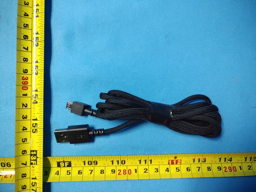
Click to zoom
Application Details
- Equipment Class
- DTS - Digital Transmission System
- Date of Grant
- Sep 02, 2020
- Application Purpose
- Original Equipment
- Date of Application
- Sep 01, 2020
- Equipment Note
- Gaming Mouse
- Frequency Range
- 2402.00000000 - 2480.00000000
- Company
- Razer Inc.
- Country
- United States
Documents & Files
Document Text
Text extracted from the exhibit documents filed with the FCC. Open a document above to read the original.
Users Manual
DATE: 24 APRIL 2020 PRODUCT MANUAL FOR GAMING MOUSE GAMING MOUSE MODEL: RZ01-0342 USB DONGLE MODEL: DGRFG7 . WHAT’S INSIDE / WHAT’S NEEDED WHAT’S INSIDE Gaming mouse (Gaming mouse model: RZ01-0342, USB Dongle: DGRFG7) A. Left mouse button B. Right mouse button C. Scroll wheel D. Left tilt-click —repeat scroll down E. Right tilt-click —repeat scroll up F. DPI stage up G. DPI stage down H. Ultraslick mouse feet I. Razer™ Focus+ 20K DPI Optical Sensor J. Profile indicator K. Profile button L. Slider switch • Razer™ HyperSpeed Wireless (2.4 Ghz) mode • Power off mode • Bluetooth mode M. 12-button side plate (recommended for MMOs) N. 7-button side plate (recommended for MOBAs) O. 2-button side plate (recommended for general use) Razer™ Speedflex charging cable USB dongle adapter Important Product Information Guide The DPI stages are as follows: 400, 800, 1600 (default), 3200 and 6400. The DPI stages can be customized using Razer Synapse. WHAT’S NEEDED PRODUCT REQUIREMENTS PC with a free USB port or Bluetooth 5.0 connectivity FOR GAMERS. BY GAMERS. ™ 1 RAZER SYNAPSE REQUIREMENTS Windows® 7 64-bit (or higher) Internet connection for software installation LET’S GET YOU COVERED You’ve got a great device in your hands, complete with a 2-year limited warranty coverage. Now maximize its potential and score exclusive Razer benefits by registering at razerid.razer.com FOR GAMERS. BY GAMERS. ™ 1 Got a question? Ask the Razer Support Team at support.razer.com Your product’s serial number can be found here. FOR GAMERS. BY GAMERS. ™ 2 GETTING STARTED CHANGING THE SIDE PLATE Pull from the bottom of the side plate to remove and then replace it with the preferred side plate. It’s recommended that you unplug the mouse first before changing side plates. To customize each side plate’s button assignments, please install Razer Synapse. FOR GAMERS. BY GAMERS. ™ 3 CHARGING YOUR MOUSE Plug the charging cable from your computer’s USB port to your Razer Naga Pro. For best results, please fully charge the mouse before using it for the first time. A depleted battery will be fully charged in approximately 4 hours. This connection also acts as the wired mode for your Razer device. The Razer Naga Pro requires a USB connection that can supply sufficient power to charge the device. The charging process may be affected when connecting to a non- powered USB hub or non-powered USB mostly found on keyboards and peripherals. It’s recommended to always connect the Razer Naga Pro directly to the USB port of your computer. LOW POWER INDICATOR The scroll wheel will blink red twice in repeated intervals to indicate that its battery’s power is less than 5%. This lighting sequence will repeat until the battery is drained or the mouse is connected to the PC via the charging cable. FOR GAMERS. BY GAMERS. ™ 4 CONNECTING YOUR MOUSE VIA RAZER™ HYPERSPEED WIRELESS (2.4 GHZ) MODE 1. Remove the attached side plate from the mouse to remove the wireless USB dongle. 2. Reattach the side plate and insert the wireless USB dongle into the USB port of your PC. 3. Push the slider switch to Razer™ HyperSpeed Wireless (2.4 GHz) mode. FOR GAMERS. BY GAMERS. ™ 5 Your Razer Naga Pro is now ready for use in wireless mode. VIA BLUETOOTH MODE 1. Push the slider switch to Bluetooth mode (). 2. Press and hold the Profile button, and the DPI stage up and DPI stage down buttons simultaneously for three seconds to activate pairing mode. The Razer logo will blink twice in repeated intervals to show that the device is in pairing mode. 3. Activate Bluetooth on your device, search for new Bluetooth devices, and select “Razer Naga Pro” from the list of devices found. FOR GAMERS. BY GAMERS. ™ 6 4. Wait until the mouse pairs with your device. When paired, the Razer logo will briefly turn static blue before displaying its current lighting effect. Once paired, your Razer Naga Pro will automatically reconnect to your device whenever in Bluetooth mode and within range. Keep the pairing devices within close proximity of each other for faster and more stable connection. Congratulations, your Razer Naga Pro is now ready to use in Bluetooth mode. USING THE WIRELESS USB DONGLE ADAPTER Use the USB dongle adapter to easily access and extend the reach of your wireless USB dongle. FOR GAMERS. BY GAMERS. ™ 7 PERSONALIZING YOUR MOUSE Use the Razer Synapse app to customize your mouse’s lighting, configure its buttons, and even create various profiles suited for different playstyles. Your Razer Naga Pro can store up to 5 profiles from the Razer Synapse app, allowing you to use these profiles even on systems without the app installed. Pressing the profile button will cycle through the different profiles, with the profile indicator’s color showing which profile is currently selected. Install Razer Synapse when prompted or download the installer from razer.com/synapse Find out more about your feature-packed wireless gaming mouse at support.razer.com Profile Designated color Active Profile White Profile 1 Red Profile 2 Green Profile 3 Blue Profile 4 Cyan Profile indicator Profile button FOR GAMERS. BY GAMERS. ™ 8 SAFETY AND MAINTENANCE SAFETY GUIDELINES Should you have trouble operating the device properly and troubleshooting does not work, unplug the device and contact the Razer hotline or go to support.razer.com for support. Do not take apart the device and do not attempt to operate it under abnormal current loads. Doing so will void your warranty. Keep the device away from liquid, humidity or moisture. Operate the device only within the specific temperature range of 0°C (32°F) to 40°C (104°F). Should the temperature exceed this range, unplug and/or switch off the device in order to let the temperature stabilize to an optimal level. COMFORT Research has shown that long periods of repetitive motion, improper positioning of your computer peripherals, incorrect body position, and poor habits may be associated with physical discomfort and injury to nerves, tendons, and muscles. Be…
Text truncated - open the document above for the full version.
Cover Letter(s)
RF_160, Issue 02 Declaration of Authorization We Name: Razer Inc. Address: 9 Pasteur, Suite 100 City: Irvine State: CA92618 Country: USA Declare that: Name Representative of agent: Ms. Rose Liu Agent Company name: BTL Inc. Address: No.3 Jinshagang 1st Road, Shixia, Dalang Town City: Dong Guan Country: China is authorized to apply for Certification and signing related documents of the following product(s), including 731 form(s): Product description: Gaming Mouse Type designation: RZ01-0342, RZ01-0342XXXX-XXXX (X can be 0-9 or A-Z) Trademark: RAZER FCC ID : RWO-RZ010342 on our behalf. Date: 2020-08-25 City: Irvine Name: Johnsen Tia Function: Senior Director, Regulatory & Compliance Signature: . Notes: (1): Required for FCC application (2): For FCC it must be the Grantee Code “owner” or the authorized agent.
Cover Letter(s)
FCC, Request for non-disclosure Date: 10-Aug-09 RF_501, Issue 5 Page 1 of 1 Company Name: Razer Inc. Address: 9 Pasteur, Suite 100 City: CA92618, Country: USA To: Telefication B.V., Dept. FCC TCB Edisonstraat 12A 6902 PK ZEVENAAR The Netherlands Subject: Request for confidentiality FCC ID: RWO-RZ010342 Reference number: ###### Dear FCC TCB, 1. Long-Term Confidentiality Pursuant to 47 CFR Section 0.459(a) & (b), we hereby requests non-disclosure and confidential treatment of the following materials submitted in support of FCC certification application: Bill(s) of Material Block Diagrams Operational Description Schematic Diagrams Tune-up Procedure Above materials contain secrets, proprietary and technical information, which would customarily be guarded from competitors under 47 CFR, section 0.457(d)(2). Disclosure or publication or any portion of this company confidential material to other parties could cause substantial competitive harm and provide unjustified benefits for competitors. 2. Short-Term Confidentiality (STC) Pursuant to Public Notice DA 04-1705 of the Commission’s policy, in order to comply with the marketing regulations in 47 CFR §2.803 and the importation rules in 47 CFR §2.1204, applicant hereby requests Short-Term Confidential treatment of the following materials (note 1): Internal Photos User’s Manual Test Set-up Photos External Photos Justification: This document contains detailed system and equipment description are considered as proprietary information in operation of the equipment. The public disclosure of above documents might be harmful to our company and would give competitor unfair advantage in the market. Planned Release Date STC: 180 days from date of grant (notes 2, 3, 4, 5) Date: 2020-08-25 Name and signature of applicant: Johnson Tia Notes: 1) A document or type of document can only have ONE type of confidentiality! 2) Short-Term confidentiality is in principle for 45 days from date of grant; it can be extended max 3 times (total time 180 days max.)! 3) FCC must be informed when marketing begins earlier. 4) Release takes place automatically thus extension must be requested in time. Telefication does not remind you of this! FCC, Request for non-disclosure Date: 10-Aug-09 RF_501, Issue 5 Page 1 of 1 5) Request for extension or for release must be received by Telefication at least 7 days before date of actual marketing or before expiration of the STC period
Cover Letter(s)
Model Declaration Letter We, the undersigning company Company Name: Razer Inc. Address: 9 Pasteur, Suite 100, Irvine, CA92618, USA. Hereby confirm that the following products: Product description: Gaming Mouse Type designation: RZ01-0342, RZ01-0342XXXX-XXXX (X can be 0-9 or A-Z) Trademark: RAZER That All versions of the Model RZ01-0342 and RZ01-0342XXXX-XXXX are electrically equal except the following difference: 1. The Model RZ01-0342 and RZ01-0342XXXX-XXXX series only differ in model name. 2. X can be 0-9 or A-Z. Date: 2020-08-25 Name: Johnsen Tia Telephone: 65 6571 6828 E-mail: [email protected] Signature:
External Photos
Report No.: 2003C188 Page 2 of 16 Report No.: 2003C188 Page 3 of 16 Report No.: 2003C188 Page 4 of 16 Report No.: 2003C188 Page 5 of 16 Report No.: 2003C188 Page 6 of 16 Report No.: 2003C188 Page 7 of 16 Report No.: 2003C188 Page 8 of 16
ID Label/Location Info
RZ01-0342 Product Label
Internal Photos
Report No.: 2003C188 Page 9 of 16 Report No.: 2003C188 Page 10 of 16 ANT Report No.: 2003C188 Page 11 of 16 Report No.: 2003C188 Page 12 of 16 Report No.: 2003C188 Page 13 of 16 Report No.: 2003C188 Page 14 of 16 Report No.: 2003C188 Page 15 of 16 Report No.: 2003C188 Page 16 of 16
RF Exposure Info
Report No.: BTL-FCCP-3-2003C188 Page 1 of 6 FCC RF EXPOSURE REPORT FCC ID: RWO-RZ010342 Project No. : 2003C188 Equipment : Gaming Mouse Brand Name : RAZER Test Model : RZ01-0342 Series Model : RZ01-0342XXXX-XXXX (X can be 0-9 or A-Z) Applicant : Razer Inc. Address : 9 Pasteur, Suite 100, Irvine, CA92618, USA. Manufacturer : Razer (Asia-Pacific) Pte.,Ltd. Address : 514 Chai Chee Lane, #07-01-06,Singapore 469029 Factory : RAZER TECHNOLOGY AND DEVELOPMENT (SHENZHEN) CO., LTD Address : East Wing, 3rd Floor, Block 2, Phase 1 of Vision Shenzhen Business Park Keji South Road, Hi-Tech Industrial Park, Shenzhen 518057, China Date of Receipt : Mar. 24, 2020 Date of Test : Mar. 25, 2020 ~ Apr. 25, 2020 Issued Date : Jun. 03, 2020 Report Version : R00 Test Sample : Sample No.: DG202004021 Standard(s) : FCC Guidelines for Human Exposure IEEE C95.1 & KDB447498 D01 The above equipment has been tested and found compliance with the requirement of the relative standards by BTL Inc. Prepared by : Welly Zhou Approved by : Ethan Ma Add: No.3, Jinshagang 1st Road, Shixia, Dalang Town,Dongguan, Guangdong, China. Te l : +86-769-8318-3000 Web: www.newbtl.com Report No.: BTL-FCCP-3-2003C188 Page 2 of 6 REPORT ISSUED HISTORY Report Version Description Issued Date R00 Original Issue. Jun. 03, 2020 Report No.: BTL-FCCP-3-2003C188 Page 3 of 6 1. GENERAL INFORMATION 1.1 GENERAL DESCRIPTION OF EUT Equipment Gaming Mouse Brand Name RAZER Te s t Model RZ01-0342 Series Model RZ01-0342XXXX-XXXX (X can be 0-9 or A-Z) Model Difference(s) The system’s model name is RZ01-0342XXXX-XXXX ( X:Can be 0-9 or A-Z), and the system is contain a Gaming Mouse (Model name: RZ01-0342) and USB Dongle(Model name: DGRFG7) Power Source 1# Supplied from battery. Model: PL782144 2# Supplied from PC USB port. Power Rating 1# DC 3.7V 700mAh 2.59Wh 2# DC 5V Product Description for LE Operation Frequency 2402 MHz ~ 2480 MHz Modulation Technology GFSK Bit Rate of Transmitter 1Mbps, 2Mbps Max. Output Power 5.09 dBm (0.0032 W) For 1Mbps 5.21 dBm (0.0033 W) For 2Mbps Product Description for 2.4G SRD Operation Frequency 2402 MHz ~ 2480 MHz Modulation Technology GFSK Bit Rate of Transmitter 2 Mbps Max. Output Power 5.18 dBm (0.0033 W) Note: 1. For a more detailed features description, please refer to the manufacturer’s specifications or the user's manual. 2. Channel List: For LE: Channel Frequency (MHz) Channel Frequency (MHz) 00 2402 20 2442 01 2404 21 2444 02 2406 22 2446 03 2408 23 2448 04 2410 24 2450 05 2412 25 2452 06 2414 26 2454 07 2416 27 2456 08 2418 28 2458 09 2420 29 2460 10 2422 30 2462 11 2424 31 2464 12 2426 32 2466 13 2428 33 2468 14 2430 34 2470 15 2432 35 2472 16 2434 36 2474 17 2436 37 2476 18 2438 38 2478 19 2440 39 2480 Report No.: BTL-FCCP-3-2003C188 Page 4 of 6 For 2.4G SRD: Channel Frequency (MHz) Channel Frequency (MHz) Channel Frequency (MHz) 00 2402 27 2429 54 2456 01 2403 28 2430 55 2457 02 2404 29 2431 56 2458 03 2405 30 2432 57 2459 04 2406 31 2433 58 2460 05 2407 32 2434 59 2461 06 2408 33 2435 60 2462 07 2409 34 2436 61 2463 08 2410 35 2437 62 2464 09 2411 36 2438 63 2465 10 2412 37 2439 64 2466 11 2413 38 2440 65 2467 12 2414 39 2441 66 2468 13 2415 40 2442 67 2469 14 2416 41 2443 68 2470 15 2417 42 2444 69 2471 16 2418 43 2445 70 2472 17 2419 44 2446 71 2473 18 2420 45 2447 72 2474 19 2421 46 2448 73 2475 20 2422 47 2449 74 2476 21 2423 48 2450 75 2477 22 2424 49 2451 76 2478 23 2425 50 2452 77 2479 24 2426 51 2453 78 2480 25 2427 52 2454 26 2428 53 2455 3. Table for Filed Antenna: LE / 2.4G SRD: Ant. Brand Model Name Antenna Type Connector Gain (dBi) 1 N/A N/A PIFA N/A 3.95 Report No.: BTL-FCCP-3-2003C188 Page 5 of 6 2. GENERAL CONCULUSION According to FCC KDB447498 D01, Appendix A, SAR Test Exclusion Thresholds for 100 MHz – 6 GHz and ≤ 50 mm, the 1-g and 10-g SAR test exclusion thresholds are determined by the following: [(max. power of channel, including tune-up tolerance, mW) / (min. test separation distance, mm)] · [√f(GHz)] ≤ 3.0 for 1-g SAR, and ≤ 7.5 for 10-g extremity SAR, where f(GHz) is the RF channel transmit frequency in GHz Power and distance are rounded to the nearest mW and mm before calculation The result is rounded to one decimal place for comparison Appendix A - SAR Test Exclusion Thresholds for 100 MHz - 6 GHz and < 50 mm MHz 5 10 15 20 25 30 35 40 45 50 mm 150 39 77 116 155 194 232 271 310 349 387 SAR Test Exclusion Thresholds (mW) 300 27 55 82 110 137 164 192 219 246 274 450 22 45 67 89 112 134 157 179 201 224 835 16 33 49 66 82 98 115 131 148 164 900 16 32 47 63 79 95 111 126 142 158 1500 12 24 37 49 61 73 86 98 110 122 1900 11 22 33 44 54 65 76 87 98 109 2450 10 19 29 38 48 57 67 77 86 96 3600 8 16 24 32 40 47 55 63 71 79 5200 7 13 20 26 33 39 46 53 59 66 5400 6 13 19 26 32 39 45 52 58 65 5800 6 12 19 25 31 37 44 50 56 62 Report No.: BTL-FCCP-3-2003C188 Page 6 of 6 3. TEST RESULTS Tune up tolerance (dBm) LE 2.4G SRD ±4 ±4 For LE: Max. Output Power (dBm) Max. Output Power (mW) Limit (mW) 9.21 8.337 10 For 2.4G SRD: Max. Output Power (dBm) Max. Output Power (mW) Limit (mW) 9.18 8.279 10 Note: (1) Output power including tune up tolerance. (2) The maximum measured output peak power of this EUT is 8.337 mW, less than 10mW at 5mm distance. Conclusion: No SAR evaluation required since transmitter power is below FCC threshold. End of Test Report
Test Report
Report No.: BTL-FCCP-2-2003C188 Page 1 of 55 FCC Radio Test Report FCC ID: RWO-RZ010342 This report concerns: Original Grant Project No. : 2003C188 Equipment : Gaming Mouse Brand Name : RAZER Test Model : RZ01-0342 Series Model : RZ01-0342XXXX-XXXX (X can be 0-9 or A-Z) Applicant : Razer Inc. Address : 9 Pasteur, Suite 100, Irvine, CA92618, USA. Manufacturer : Razer (Asia-Pacific) Pte.,Ltd. Address : 514 Chai Chee Lane, #07-01-06,Singapore 469029 Factory : RAZER TECHNOLOGY AND DEVELOPMENT (SHENZHEN) CO., LTD Address : East Wing, 3rd Floor, Block 2, Phase 1 of Vision Shenzhen Business Park Keji South Road, Hi-Tech Industrial Park, Shenzhen 518057, China Date of Receipt : Mar. 24, 2020 Date of Test : Mar. 25, 2020 ~ Apr. 25, 2020 Issued Date : Jun. 03, 2020 Report Version : R00 Test Sample : Sample No.: DG202004021 for conducted, DG202004022 for radiated. Standard(s) : FCC Part15, Subpart C (15.247) ANSI C63.10-2013 FCC KDB 558074 D01 15.247 Meas Guidance V05r02 The above equipment has been tested and found compliance with the requirement of the relative standards by BTL Inc. Prepared by : Welly Zhou Approved by : Ethan Ma Add: No.3, Jinshagang 1st Road, Shixia, Dalang Town,Dongguan, Guangdong, China. Te l : +86-769-8318-3000 Web: www.newbtl.com Report No.: BTL-FCCP-2-2003C188 Page 2 of 55 Declaration BTL represents to the client that testing is done in accordance with standard procedures as applicable and that test instruments used has been calibrated with standards traceable to international standard(s) and/or national standard(s). BTL's reports apply only to the specific samples tested under conditions. It is manufacture’s responsibility to ensure that additional production units of this model are manufactured with the identical electrical and mechanical components. BTL shall have no liability for any declarations, inferences or generalizations drawn by the client or others from BTL issued reports. The report must not be used by the client to claim product certification, approval, or endorsement by NVLAP, NIST, A2LA, or any agency of the U.S. Government. This report is the confidential property of the client. As a mutual protection to the clients, the public and ourselves, the test report shall not be reproduced, except in full, without our written approval. BTL’s laboratory quality assurance procedures are in compliance with the ISO/IEC 17025 requirements, and accredited by the conformity assessment authorities listed in this test report. BTL is not responsible for the sampling stage, so the results only apply to the sample as received. The information, data and test plan are provided by manufacturer which may affect the validity of results, so it is manufacturer’s responsibility to ensure that the apparatus meets the essential requirements of applied standards and in all the possible configurations as representative of its intended use. Limitation For the use of the authority's logo is limited unless the Test Standard(s)/Scope(s)/Item(s) mentioned in this test report is (are) included in the conformity assessment authorities acceptance respective. Please note that the measurement uncertainty is provided for informational purpose only and are not use in determining the Pass/Fail results. Report No.: BTL-FCCP-2-2003C188 Page 3 of 55 Table of Contents Page REPORT ISSUED HISTORY 5 1 . SUMMARY OF TEST RESULTS 6 1.1 TEST FACILITY 7 1.2 MEASUREMENT UNCERTAINTY 7 1.3 TEST ENVIRONMENT CONDITIONS 7 2 . GENERAL INFORMATION 8 2.1 GENERAL DESCRIPTION OF EUT 8 2.2 DESCRIPTION OF TEST MODES 10 2.3 PARAMETERS OF TEST SOFTWARE 10 2.4 BLOCK DIAGRAM SHOWING THE CONFIGURATION OF SYSTEM TESTED 11 2.5 SUPPORT UNITS 11 3 . AC POWER LINE CONDUCTED EMISSIONS TEST 12 3.1 LIMIT 12 3.2 TEST PROCEDURE 12 3.3 DEVIATION FROM TEST STANDARD 12 3.4 TEST SETUP 13 3.5 EUT OPERATING CONDITIONS 13 3.6 TEST RESULTS 13 4 . RADIATED EMISSION TEST 14 4.1 LIMIT 14 4.2 TEST PROCEDURE 15 4.3 DEVIATION FROM TEST STANDARD 15 4.4 TEST SETUP 16 4.5 EUT OPERATING CONDITIONS 17 4.6 TEST RESULT - 9 KHZ TO 30 MHZ 17 4.7 TEST RESULT - 30 MHZ TO 1000 MHZ 17 4.8 TEST RESULT - ABOVE 1000 MHZ 17 5 . BANDWIDTH TEST 18 5.1 LIMIT 18 5.2 TEST PROCEDURE 18 5.3 DEVIATION FROM STANDARD 18 5.4 TEST SETUP 18 5.5 EUT OPERATION CONDITIONS 18 Report No.: BTL-FCCP-2-2003C188 Page 4 of 55 Table of Contents Page 5.6 TEST RESULTS 18 6 . MAXIMUM OUTPUT POWER 19 6.1 LIMIT 19 6.2 TEST PROCEDURE 19 6.3 DEVIATION FROM STANDARD 19 6.4 TEST SETUP 19 6.5 EUT OPERATION CONDITIONS 19 6.6 TEST RESULTS 19 7 . CONDUCTED SPURIOUS EMISSION 20 7.1 LIMIT 20 7.2 TEST PROCEDURE 20 7.3 DEVIATION FROM STANDARD 20 7.4 TEST SETUP 20 7.5 EUT OPERATION CONDITIONS 20 7.6 TEST RESULTS 20 8 . POWER SPECTRAL DENSITY TEST 21 8.1 LIMIT 21 8.2 TEST PROCEDURE 21 8.3 DEVIATION FROM STANDARD 21 8.4 TEST SETUP 21 8.5 EUT OPERATION CONDITIONS 21 8.6 TEST RESULTS 21 9 . MEASUREMENT INSTRUMENTS LIST 22 APPENDIX A - AC POWER LINE CONDUCTED EMISSIONS 24 APPENDIX B - RADIATED EMISSION - 9 KHZ TO 30 MHZ 27 APPENDIX C - RADIATED EMISSION - 30 MHZ TO 1000 MHZ 32 APPENDIX D - RADIATED EMISSION - ABOVE 1000 MHZ 35 APPENDIX E - BANDWIDTH 48 APPENDIX F - MAXIMUM OUTPUT POWER 50 APPENDIX G - CONDUCTED SPURIOUS EMISSION 52 APPENDIX H - POWER SPECTRAL DENSITY 54 Report No.: BTL-FCCP-2-2003C188 Page 5 of 55 REPORT ISSUED HISTORY Report Version Description Issued Date R00 Original Issue. Jun. 03, 2020 Report No.: BTL-FCCP-2-2003C188 Page 6 of 55 1. SUMMARY OF TEST RESULTS Test procedures according to the technical standard(s): FCC Part15, Subpart C (15.247) Standard(s) Section Test Item Test Result Judgment Remark 15.207 AC Power Line Conducted Emissions APPENDIX A PASS ------ 15.247(d) 15.205(a) 15.209(a) Radiated Emissions APPENDIX B APPENDIX C APPENDIX D PASS ------ 15.247(a)(2) Bandwidth APPENDIX E PASS ------ 15.247(b)(3) Maximum Output Power APPENDIX F PASS ------ 15.247(d) Conducted Spurious Emission APPENDIX G PASS ------ 15.247(e) Power Spectral Density APPENDIX H PASS ------ 15.203 Antenna Requiremen…
Text truncated - open the document above for the full version.
Test Report
Report No.: BTL-FCCP-1-2003C188 Page 1 of 71 FCC Radio Test Report FCC ID: RWO-RZ010342 This report concerns: Original Grant Project No. : 2003C188 Equipment : Gaming Mouse Brand Name : RAZER Test Model : RZ01-0342 Series Model : RZ01-0342XXXX-XXXX (X can be 0-9 or A-Z) Applicant : Razer Inc. Address : 9 Pasteur, Suite 100, Irvine, CA92618, USA. Manufacturer : Razer (Asia-Pacific) Pte.,Ltd. Address : 514 Chai Chee Lane, #07-01-06,Singapore 469029 Factory : RAZER TECHNOLOGY AND DEVELOPMENT (SHENZHEN) CO., LTD Address : East Wing, 3rd Floor, Block 2, Phase 1 of Vision Shenzhen Business Park Keji South Road, Hi-Tech Industrial Park, Shenzhen 518057, China Date of Receipt : Mar. 24, 2020 Date of Test : Mar. 25, 2020 ~ Apr. 25, 2020 Issued Date : Jun. 03, 2020 Report Version : R00 Test Sample : Sample No.: DG202004021 for conducted, DG202004022 for radiated. Standard(s) : FCC Part15, Subpart C (15.247) ANSI C63.10-2013 FCC KDB 558074 D01 15.247 Meas Guidance v05r02 The above equipment has been tested and found compliance with the requirement of the relative standards by BTL Inc. Prepared by : Welly Zhou Approved by : Ethan Ma Add: No.3, Jinshagang 1st Road, Shixia, Dalang Town,Dongguan, Guangdong, China. Te l : +86-769-8318-3000 Web: www.newbtl.com Report No.: BTL-FCCP-1-2003C188 Page 2 of 71 Declaration BTL represents to the client that testing is done in accordance with standard procedures as applicable and that test instruments used has been calibrated with standards traceable to international standard(s) and/or national standard(s). BTL's reports apply only to the specific samples tested under conditions. It is manufacture’s responsibility to ensure that additional production units of this model are manufactured with the identical electrical and mechanical components. BTL shall have no liability for any declarations, inferences or generalizations drawn by the client or others from BTL issued reports. The report must not be used by the client to claim product certification, approval, or endorsement by NVLAP, NIST, A2LA, or any agency of the U.S. Government. This report is the confidential property of the client. As a mutual protection to the clients, the public and ourselves, the test report shall not be reproduced, except in full, without our written approval. BTL’s laboratory quality assurance procedures are in compliance with the ISO/IEC 17025 requirements, and accredited by the conformity assessment authorities listed in this test report. BTL is not responsible for the sampling stage, so the results only apply to the sample as received. The information, data and test plan are provided by manufacturer which may affect the validity of results, so it is manufacturer’s responsibility to ensure that the apparatus meets the essential requirements of applied standards and in all the possible configurations as representative of its intended use. Limitation For the use of the authority's logo is limited unless the Test Standard(s)/Scope(s)/Item(s) mentioned in this test report is (are) included in the conformity assessment authorities acceptance respective. Please note that the measurement uncertainty is provided for informational purpose only and are not use in determining the Pass/Fail results. Report No.: BTL-FCCP-1-2003C188 Page 3 of 71 Table of Contents Page REPORT ISSUED HISTORY 6 1 . SUMMARY OF TEST RESULTS 7 1.1 TEST FACILITY 8 1.2 MEASUREMENT UNCERTAINTY 8 1.3 TEST ENVIRONMENT CONDITIONS 8 2 . GENERAL INFORMATION 9 2.1 GENERAL DESCRIPTION OF EUT 9 2.2 DESCRIPTION OF TEST MODES 10 2.3 PARAMETERS OF TEST SOFTWARE 11 2.4 BLOCK DIAGRAM SHOWING THE CONFIGURATION OF SYSTEM TESTED 12 2.5 SUPPORT UNITS 12 3 . AC POWER LINE CONDUCTED EMISSIONS TEST 13 3.1 LIMIT 13 3.2 TEST PROCEDURE 13 3.3 DEVIATION FROM TEST STANDARD 13 3.4 TEST SETUP 14 3.5 EUT OPERATING CONDITIONS 14 3.6 TEST RESULTS 14 4 . RADIATED EMISSION TEST 15 4.1 LIMIT 15 4.2 TEST PROCEDURE 16 4.3 DEVIATION FROM TEST STANDARD 16 4.4 TEST SETUP 17 4.5 EUT OPERATING CONDITIONS 18 4.6 TEST RESULT - 9 KHZ TO 30 MHZ 18 4.7 TEST RESULT - 30 MHZ TO 1000 MHZ 18 4.8 TEST RESULT - ABOVE 1000 MHZ 18 5 . BANDWIDTH TEST 19 5.1 LIMIT 19 5.2 TEST PROCEDURE 19 5.3 DEVIATION FROM STANDARD 19 Report No.: BTL-FCCP-1-2003C188 Page 4 of 71 Table of Contents Page 5.4 TEST SETUP 19 5.5 EUT OPERATION CONDITIONS 19 5.6 TEST RESULTS 19 6 . MAXIMUM OUTPUT POWER 20 6.1 LIMIT 20 6.2 TEST PROCEDURE 20 6.3 DEVIATION FROM STANDARD 20 6.4 TEST SETUP 20 6.5 EUT OPERATION CONDITIONS 20 6.6 TEST RESULTS 20 7 . CONDUCTED SPURIOUS EMISSION 21 7.1 LIMIT 21 7.2 TEST PROCEDURE 21 7.3 DEVIATION FROM STANDARD 21 7.4 TEST SETUP 21 7.5 EUT OPERATION CONDITIONS 21 7.6 TEST RESULTS 21 8 . POWER SPECTRAL DENSITY TEST 22 8.1 LIMIT 22 8.2 TEST PROCEDURE 22 8.3 DEVIATION FROM STANDARD 22 8.4 TEST SETUP 22 8.5 EUT OPERATION CONDITIONS 22 8.6 TEST RESULTS 22 9 . MEASUREMENT INSTRUMENTS LIST 23 APPENDIX A - AC POWER LINE CONDUCTED EMISSIONS 25 APPENDIX B - RADIATED EMISSION - 9 KHZ TO 30 MHZ 28 APPENDIX C - RADIATED EMISSION - 30 MHZ TO 1000 MHZ 33 APPENDIX D - RADIATED EMISSION - ABOVE 1000 MHZ 36 APPENDIX E - BANDWIDTH 61 Report No.: BTL-FCCP-1-2003C188 Page 5 of 71 Table of Contents Page APPENDIX F - MAXIMUM OUTPUT POWER 63 APPENDIX G - CONDUCTED SPURIOUS EMISSION 65 APPENDIX H - POWER SPECTRAL DENSITY 70 Report No.: BTL-FCCP-1-2003C188 Page 6 of 71 REPORT ISSUED HISTORY Report Version Description Issued Date R00 Original Issue. Jun. 03, 2020 Report No.: BTL-FCCP-1-2003C188 Page 7 of 71 1. SUMMARY OF TEST RESULTS Test procedures according to the technical standard(s): FCC Part15, Subpart C (15.247) Standard(s) Section Test Item Test Result Judgment Remark 15.207 AC Power Line Conducted Emissions APPENDIX A PASS ------ 15.247(d) 15.205(a) 15.209(a) Radiated Emissions APPENDIX B APPENDIX C APPENDIX D PASS ------ 15.247(a)(2) Bandwidth APPENDIX E PASS ------ 15.247(b)(3) Maximum Output Power APPENDIX F PASS ------ 15.247(d) Conducted Spurious Emission APPENDIX G PASS ------ 15.247(e) Pow…
Text truncated - open the document above for the full version.
Test Setup Photos
Report No.: 2003C188 Page 1 of 5 EUT TEST PHOTO Report No.: 2003C188 Page 2 of 5 AC Power Line Conducted Emissions Test Photos Report No.: 2003C188 Page 3 of 5 Radiated Emissions Test Photos 9 kHz to 30 MHz Report No.: 2003C188 Page 4 of 5 Radiated Emissions Test Photos 30 MHz to 1000 MHz Report No.: 2003C188 Page 5 of 5 Radiated Emissions Test Photos Above 1 GHz
Contact Information
Applicant
Johnsen Tia(Director, Regulatory & Compliance)
Technical Contact
Non-Technical Contact
BTL Inc.Rose Liu
[email protected]86-769-83183000
Test Firm
BTL Inc.Sophia Huang
[email protected]+86-769-83183000
Technical Specifications
| # | Rule Parts | Frequency Range | Power Output |
|---|---|---|---|
| 1 | 15C | 2.40 GHz - 2.48 GHz | 3.30 mW |
Other Applications from Razer Inc.
RWO-RZ060519
Sep 02, 2026Gaming Controller
Equipment Class
DTS - Digital Transmission SystemRWO-RZ010566
Aug 26, 2026Gaming Mouse
Equipment Class
DTS - Digital Transmission SystemRWO-RZ380426
Jun 26, 2026Gaming Chair
Equipment Class
DTS - Digital Transmission SystemRWO-DGRFG8
May 28, 2026Wireless Dongle
Equipment Class
DTS - Digital Transmission SystemRWO-RZ010569
May 27, 2026Wireless Mouse
Equipment Class
DTS - Digital Transmission System