RXN10RR1Electronic register with embedded M2 radio
Transparent Technologies, Inc.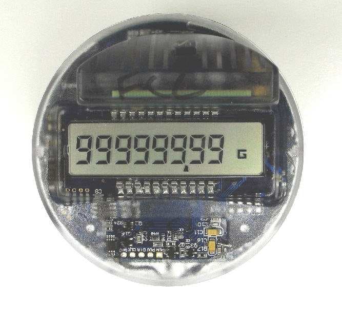
Click to zoom
Application Details
- Equipment Class
- DTS - Digital Transmission System
- Date of Grant
- Dec 26, 2010
- Application Purpose
- Original Equipment
- Date of Application
- Dec 26, 2010
- Equipment Note
- Electronic register with embedded M2 radio
- Frequency Range
- 903.00000000 - 927.00000000
- Country
- United States
Documents & Files
Document Text
Text extracted from the exhibit documents filed with the FCC. Open a document above to read the original.
Users Manual
TR A N S P A R E N T TE C H N O L O G I E S E-Reg / E -Reg -R Electronic Register With optional Embedded Radio Operations Manual Transparent Technologies, Inc 5665 Airport Blvd Boulder, CO 80301 720-406-1294 Disclaimer In no event shall Transparent Technologies be liable for any incidental, indirect, or consequential damages or other damages including without limitation loss of profits, loss of revenue, loss of data, loss of use of the product or any associated equipment, downtime, and user’s time associated with the use of this product, the resale hardware or its software. Use of Hardware In no event shall Transparent Technologies be liable for damages resulting from the use of its hardware or the malfunction of that hardware. Specifications for the hardware are subject to change at any time without notice. Copyrights /Trademarks Transparent Technologies reserves the names T2, E-Reg, E-Reg-R, M2w and UDA. References are made to Sony®, Clie™and Palm©. Version E-Reg Version 01.00 October 2010 O OO OVERVIEW VERVIEWVERVIEW VERVIEW 1 11 1 I II INSTALLATION NSTALLATION NSTALLATION NSTALLATION 2 22 2 O OO OPERATION PERATIONPERATION PERATION 3 33 3 O OO OPTIONAL PTIONAL PTIONAL PTIONAL R RR RADIO ADIOADIO ADIO 4 44 4 B BB BATTERY ATTERYATTERY ATTERY 5 55 5 A AA APPENDIX PPENDIX PPENDIX PPENDIX 6 66 6 E EE E- -- -Reg RegReg Reg E EE E- -- -Reg RegReg Reg- -- -R RR R Electronic Register With Embedded Radio Installation & Operations Manual 1 1 E-Reg Electronic Register The E-Reg is the water industry’s new standard for register performance. The E-Reg offers maximum register resolution, a multitude of standard features, on-board datalogging and a variety of AMR and SCADA output options, including an embedded T2 M2w AMR radio. The E-Reg is designed for all environments and incorporates the largest battery available for AMR/utility applications. The E-Reg can be deployed on any Metron Spectrum or Enduro model and can be configured for USG, Ft3 or m3 billing units. Register Features - 8-digit Display with Configurable Decimal Point - Total or Flowrate Display - Test Mode for Meter Testing - Measuring Unit Indication - Flowrate Unit Indication - Forward & Reverse Flowrate Indication - Permanent “Under-Glass” ID Label w/Barcode Options Embedded Spread Spectrum Radio w/Integral Antenna (shown above) 3-Wire AMR (C-D-G) Output Pulse (switch) Output SCADA (4-20mA) Output Valve Control (switch) Output OVERVIEW 2 1 E-Reg Packaging The E-Reg is housed in a polycarbonate shell with multiple levels of waterproofing. The housing is assembled with a UV- cure adhesive which provides the first level of environmental protection. The register and radio electronics are 100% encapsulated in a dielectric gel for 100% moisture protection. Finally, all cable entry/exit points are sealed with gel grommets to protect against long- term moisture penetration. The product label indicates a model number with a corresponding the FCC identifier. E-Reg E-Reg-R 3 1 Basic Specifications Materials Inner Housing: Polycarbonate UV-protected Sealing: Self-Healing Dielectric Gel Environmental Temperature: –4 o F to +176 o F –20 o C to +80 o C Humidity Range: 100% (waterproof) Rating: IP68 (Fully submersible) Battery: Replaceable 19.0 A-hr D-cell Battery Life: Up to 15 years Optional Embedded M2w Radio Transmission: One-Way Config/Datalogging: Two-Way (unregulated) Regulatory: FCC 15.247 4 1 E-Reg LCD Display 1 2 Installation The E-Reg is designed for all environments and can be installed either in indoor or outdoor environments. The register is attached to the Metron water meter with a plastic housing as shown below. INSTALLATION & WIRING 2 2 Step 1 Fit the E-Reg inside the bottom housing as shown. The tabs will keep the E-Reg from slipping downward. Step 2 Place the top housing over the E-Reg and press downward until the top housing clicks into place. 3 2 Step 3 Start the screw into the separate slide crimp as shown below. The slide crimp will secure the bottom and top housings together. Do not fully tighten the screw at this point. Step 4 Place the E-Reg assembly on the water meter. Any MP3 or MP5 meter will have either a brass or plastic register plate for the attachment. 4 2 Step 5 Once the E-Reg assembly is loosely attached to the water meter, continue tightening the screw. The tightening will contract the bottom housing so the assembly is securely attached to the water meter. 5 2 Radio Option The E-Reg can be supplied with a optional M2w radio (E-Reg-R). This radio will be fully embedded within the E-Reg housing. The antenna is an integral circuit board that extends approximately 1 inch above the face of the E-Reg. There are no connections or wiring for the embedded M2w radio. 6 2 1 3 To be completed OPERATION 1 4 The E-Reg has a battery with an anticipated battery life of 15 years . Battery Specifications Mfg: Vitzrocell Type: Thionyl Lithium Chloride Size: D-cell Capacity: 19.0 A-hr Battery Life All battery calculations include a environmental impact factor and use a baseline of regular function usage (PDA reads, datalogging, etc.) With the optional M2w radio, the E- Reg’s transmit period is directly related to the battery life of the radio. The RF transmission is the largest power consumer and thus drives battery life. Check with Transparent Technologies for a detailed battery life calculation based on specific configurations. BATTERY 1 6 FCC Information Information to user. - The users manual or instruction manual for an intentional or unintentional radiator shall caution the user that changes or modifications not expressly approved by the party responsible for compliance could void the user's authority to operate the equipment. Special accessories. (a) Equipment marketed to a consumer must be capable of complying with the necessary regulations in the configuration in which the equipment is marketed. Where special accessories, such as shielded cables and/or special connectors, are required to enable an unintentional or intention…
Text truncated - open the document above for the full version.
Attestation Statements
Transparent Technologies, Inc. 5665 Airport Blvd Boulder, CO 80301 www.transparenttech.com October 25, 2010 Federal Communications Commission 7435 Oakland Mills Road Columbia, MD 21046 We the undersigned, hereby certify that, in the case of individual applicant, he or she is not subject to a denial of federal benefits pursuant to section 5301 of the Anti-Drug Abuse Act of 1988, 21 USC 853a or in the case of non-individual applicant (e.g. corporation, partnership or other unincorporated association), no party to the applicant is subject to a denial of federal benefit pursuant to that action. Sincerely, Mark Shamley Operations Manager Transparent Technologies, Inc.
Attestation Statements
Transparent Technologies, Inc. 5665 Airport Blvd Boulder, CO 80301 www.transparenttech.com • Provide a statement for how your device Complies with FCC15.203 Antenna requirement: An intentional radiator shall be designed to ensure that no antenna other than that furnished by the responsible party shall be used with the device. The use of a permanently attached antenna or of an antenna that uses a unique coupling to the intentional radiator shall be considered sufficient to comply with the provisions of this section. The manufacturer may design the unit so that a broken antenna can be replaced by the user, but the use of a standard antenna jack or electrical connector is prohibited. This requirement does not apply to carrier current devices or to devices operated under the provisions of §§15.211, 15.213, 15.217, 15.219, or 15.221. Further, this requirement does not apply to intentional radiators that must be professionally installed, such as perimeter protection systems and some field disturbance sensors, or to other intentional radiators which, in accordance with §15.31(d), must be measured at the installation site. However, the installer shall be responsible for ensuring that the proper antenna is employed so that the limits in this part are not exceeded. E-Reg-R: The integral antenna is etched on the printed circuit board and is permanently attached via solder to the E-Reg PCA. The primary PCA and the integral antenna PCB are encased within a permanently sealed and potted plastic enclosure.
Cover Letter(s)
Transparent Technologies, Inc. 5665 Airport Blvd Boulder, CO 80301 P720-406-1294 F303-441-0203 www.transparenttech.com October 25, 2010 Mr. Bryant Hart Intertek Testing Services NA, Inc. 5541 Central Ave, Suite 110 Boulder, CO 80301 Mr. Hart: We the undersigned, hereby authorize Intertek Testing Services NA, Inc., to act on our behalf in all legal manners relating to application for equipment authorization to include the transfer the information contained herein to a TCB or regulatory agency, and sign all documents relating to these matters. Any and all legal acts carried out by Intertek Testing Services NA, Inc., on our behalf shall have the same affect as acts of our own. This authorization is valid until further written notice from Transparent Technologies, Inc. Sincerely, Mark Shamley Operations Manager Transparent Technologies, Inc.
Cover Letter(s)
Letter of Agency I appoint Intertek Testing Services NA Inc. to act on our behalf in front of the Federal Communications Commission with respect to all matters relating to certification of equipment under the FCC rules until further notice. I further certify that no party (as defined in 1.2002 of CFR 47, 1995) to this application, including myself, is subject to denial of federal benefits, that includes FCC benefits, pursuant to Section 5301 of the Anti-Drug Abuse Act of 1988, 21 U.S.C.,853A. Equipment: E-Reg-R Electronic Register with Embedded M2 Radio Dated this 25 th day of October, 2010. ____________________________________ Signature Mark Shamley Name Operations Manager Title Transparent Technologies, Inc. Company 720-406-1294 Telephone
Cover Letter(s)
Transparent Technologies, Inc. 5665 Airport Blvd Boulder, CO 80301 P720-406-1294 F303-441-0203 www.transparenttech.com Attention: Application Examiner Reviewing Engineer Re: Request for confidentiality per Section 0.459 of FCC Rules Applicant: Transparent Technologies, Inc. FCC ID: RXN10RR1 Model : E-Reg-R Electronic Register with Embedded M2 Radio To whom it may concern, Request is hereby submitted by Transparent Technologies, Inc.., to withhold from public review certain portions of the application for equipment certification for the referenced FCC identifier. In particular, the following sections of the application and report are requested to be kept confidential: • All Schematics o MCU o Power o RF Block o RF XE1203F • All Bill of Materials • Detailed Block diagrams • Detailed Operational/Functional Description • Internal photos Rationale for request for confidentiality: Transparent Technologies, Inc. wishes to keep these items confidential to maintain a competitive advantage in the marketplace. The $125 fee for confidentiality has been submitted along with the fee for certification. If you have questions or need further information, please contact the undersigned. Sincerely, Mark Shamley Operations Manager Transparent Technologies, Inc.
External Photos
E-Reg-R Product External Photos Top View Bottom View Side View 1 Side View 2
ID Label/Location Info
barcode 01234567 E-REG-R barcode 01234567 E-REG THIS DEVICE COMPLIES WITH PART 15 OF THE FCC RULES. OPERATION IS SUBJECT TO THE FOLLOWING TWO CONDITIONS: (1) THIS DEVICE MAY NOT CAUSE HARMFUL INTERFERENCE, AND (2) THIS DEVICE MUST ACCEPT ANY INTERFERENCE RECEIVED, INCLUDING INTERFERENCE THAT MAY CAUSE UNDESIRED OPERATION. FCC ID: RXN10RR1 IC ID: 6872A-10RR1 E-REG-R Transparent Technologies 1.3” 0.45” 0.70” 1.26” Serial Number and FCC Labels are “windshield” labels applied to inside of transparent housing. - Serial Number label is applied to upper housing below LCD. - FCC disclaimer label is applied to side of lower housing. TITLE SHEET___OF___ Date SIZE B DWG #: REV TBD1.0.0 6/26/10 E-Reg Labels THIS DEVICE COMPLIES WITH PART 15 OF THE FCC RULES. OPERATION IS SUBJECT TO THE FOLLOWING TWO CONDITIONS: (1) THIS DEVICE MAY NOT CAUSE HARMFUL INTERFERENCE, AND (2) THIS DEVICE MUST ACCEPT ANY INTERFERENCE RECEIVED, INCLUDING INTERFERENCE THAT MAY CAUSE UNDESIRED OPERATION. FCC ID: RXN10RR1 IC ID: 6872A-10RR1 E-REG-R Transparent Technologies Serial Number Label FCC Label
Test Report
This report is for the exclusive use of Intertek's Client and is provided pursuant to the agreement between Intertek and its Client. Intertek's responsibility and liability are limited to the terms and conditions of the agreement. Intertek assumes no liability to any party, other than to the Client in accordance with the agreement, for any loss, expense or damage occasioned by the use of this report. Only the Client is authorized to permit copying or distribution of this report and then only in its entirety. Any use of the Intertek name or one of its marks for the sale or advertisement of the tested material, product or service must first be approved in writing by Intertek. The observations and test results in this report are relevant only to the sample tested. This report by itself does not imply that the material, product, or service is or has ever been under an Intertek certification program. EMC Report for Transparent Technologies on the Model: E-Reg-R Page 1 of 39 TEST REPORT – EMC Emissions Report Number: 100211930DEN-001 Project Number: 100211930 Report Issue Date: 12/9/2010 Product Designation: Model: E-Reg-R (Electronic Register with Embedded M2 Radio) Standards: FCC 47 CFR Part 15.247 IC RSS 210: Issue 7 IC RSS-GEN Issue 2: 2007 Tested by: Client: Intertek Testing Services NA, Inc. 1795 Dogwood Street, Suite 200 Louisville, CO 80027 Emissions Testing Facility 40 Meadow Rd Pinewood Springs, CO 80540 Transparent Technologies 5665 Airport Blvd. Boulder, CO 80301 Report prepared by Report reviewed by Randy Thompson Senior EMC Project Engineer Michael Spataro Engineering Team Leader Intertek Report Number: 100211930DEN-001 Issued: 12/9/2010 EMC Report for Transparent Technologies on the Model: E-Reg-R Page 2 of 39 TABLE OF CONTENTS Section Page 1 Introduction and Conclusion .............................................................................................................. 4 2 Test Summary ...................................................................................................................................... 4 3 Description of Equipment Under Test ............................................................................................... 6 4 System setup including cable interconnection details, support equipment and simplified block diagram ........................................................................................................................................................ 7 5 Radiated Emissions – Field Strength of the Fundamental & Harmonics of the Fundamental..... 9 6 Radiated Emissions – Unintentional and Spurious........................................................................ 16 7 6dB Bandwidth ................................................................................................................................... 22 8 Power Spectral Density (PSD) .......................................................................................................... 26 9 Occupied Bandwidth (OBW) ............................................................................................................. 31 10 Band Edge Measurements............................................................................................................. 35 11 AC Conducted Emissions – Not Applicable (Product Battery-Powered) ................................. 37 12 Measurement Uncertainty.............................................................................................................. 38 13 Revision History ............................................................................................................................. 39 Intertek Report Number: 100211930DEN-001 Issued: 12/9/2010 EMC Report for Transparent Technologies on the Model: E-Reg-R Page 3 of 39 Product Under Test E-Reg-R (Electronic Register with Embedded M2 Radio) Intertek Report Number: 100211930DEN-001 Issued: 12/9/2010 EMC Report for Transparent Technologies on the Model: E-Reg-R Page 4 of 39 1 Introduction and Conclusion The tests indicated in section 2.0 were performed on the product constructed as described in section 3.0. The remaining test sections are the verbatim text from the actual data sheets used during the investigation. These test sections include the test name, the specified test Method, a list of the actual Test Equipment Used, documentation Photos, Results and raw Data. No additions, deviations, or exclusions have been made from the standard(s) unless specifically noted. Based on the results of our investigation, we have concluded the product tested complies with the requirements of the standard(s) indicated. The results obtained in this test report pertain only to the item(s) tested. 2 Test Summary Section Test full name Test date Result 5 Radiated Emissions – Field Strength of the Fundamental & Harmonics of the Fundamental - FCC 247(b)(3) (d)/15.205 (Covers RSS-210 A8.4(4) & A8.5) 10/14/2010 Pass 6 Radiated Emissions – Unintentional & Spurious - FCC 15.209/ 15.247(d) (Covers RSS-210, Section 2.7, Tables 2 & 3) 10/15/2010 Pass 7 6dB Bandwidth – FCC 15.247 (a)(2) (Covers RSS-210 A8.2(a)) 10/21/2010 Pass 8 Power Spectral Density (PSD) – FCC 15.247(e) (Covers RSS-210 A8.2(b)) 10/21/2010 Pass 9 Occupied Bandwidth - RSS-GEN, Section 4.6.1 10/21/2010 Pass 10 Band Edge Measurements – FCC 15.247(d) / 15.209 (Covers RSS-210, A8.5 & Section 2.7, Table 2) 10/14/2010 Pass 11 AC Conducted Emissions – FCC 15.207 – Not Applicable ----- N/A Notes: 1) Product is battery-powered – therefore, Conducted Emissions does not apply. 2) Intertek Report Number: 100211930DEN-001 Issued: 12/9/2010 EMC Report for Transparent Technologies on the Model: E-Reg-R Page 5 of 39 General Remarks: The following remarks are to be considered as “where applicable” and are taken into account while completing any FCC/IC/ETSI Radio tests at Intertek-Louisville. Testing was performed in 3 different orthogonal axes to determine the worst-case emissions from the device. The worst-case axis…
Text truncated - open the document above for the full version.
Test Setup Photos
E-Reg-R Test Setup Photos Intentional Radiated Emissions & PSD (Front View) Intentional Radiated Emissions – Axis 1 (Specified Operating Position) Unintentional Radiated Emissions (Front View) Unintentional Radiated Emissions (Rear View) Bandwidth & Timing Measurements
Contact Information
Applicant
Brian Hulsey
Technical Contact
Transparent Technologies, Inc.Duane Switzer
[email protected]720-258-1278
5665 Airport Blvd. · Boulder, Colorado · United States
Non-Technical Contact
Transparent Technologies, Inc.Rod Ehlers
[email protected]720-406-1294
Test Firm
Intertek Testing Services NA, Inc.Jay Kogoma
Technical Specifications
| # | Rule Parts | Frequency Range | Power Output | Emission |
|---|---|---|---|---|
| 1 | 15C | 903 MHz - 927 MHz | 31.60 mW | 605KF7D |
Other Applications from Transparent Technologies, Inc.
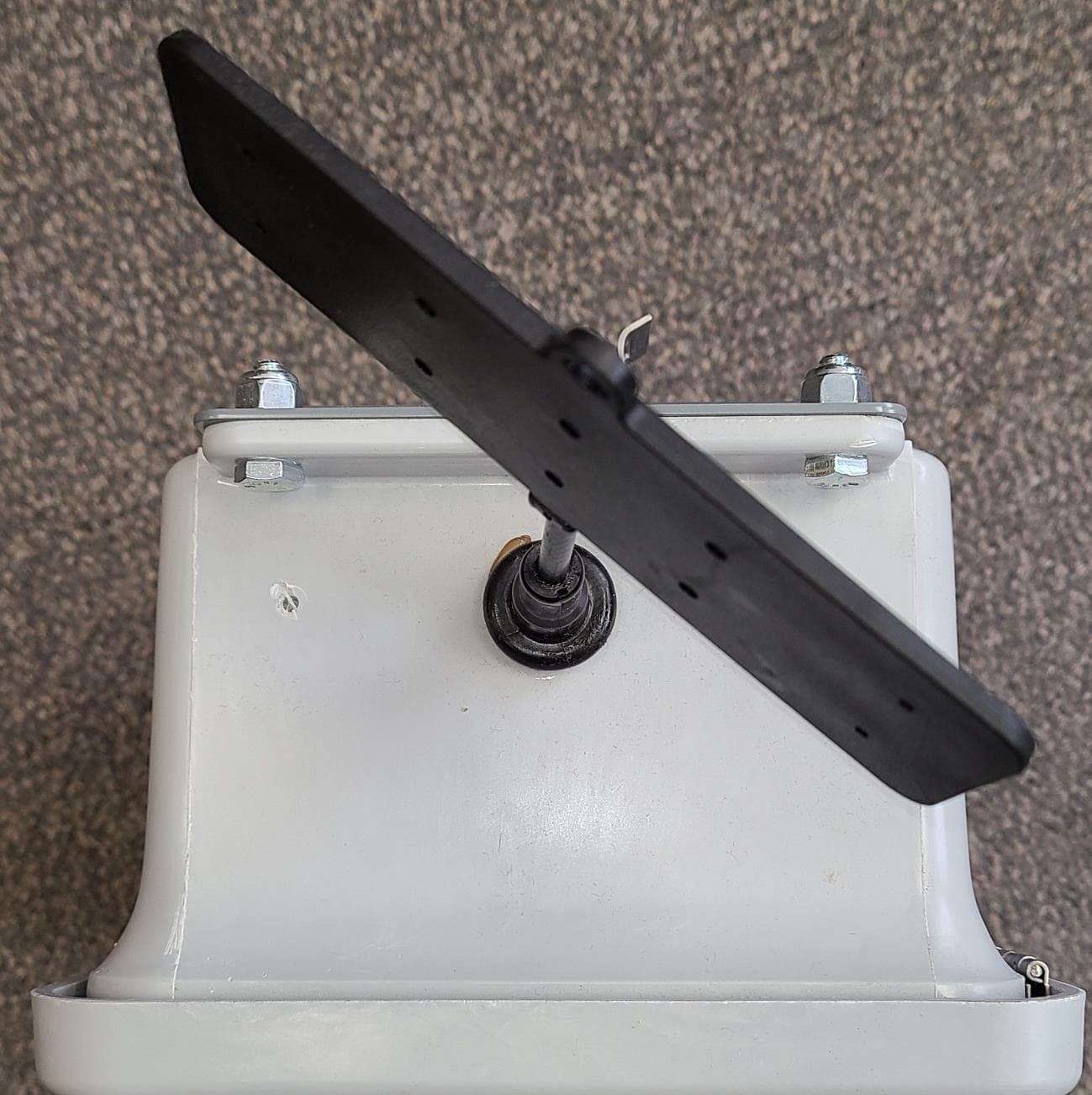
RXNGW1BH1025
May 31, 2021The Gateway is a device to bridge the gap of meters in the field and our server.
Equipment Class
DTS - Digital Transmission System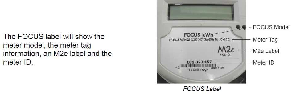
RXN1M2ESS
Nov 11, 2012Models AL & AX Landis & Gyr FOCUS Electric Meters with M2e Radio
Equipment Class
DTS - Digital Transmission System
RXN1207R2SSL
Jan 22, 2008R2 Utility Radio Transceiver
Equipment Class
DTS - Digital Transmission System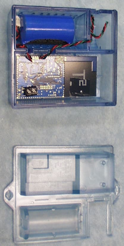
RXN610M2SSL
Sep 17, 2007M2 Utility Radio Transceiver
Equipment Class
DXT - Part 15 Low Power Transceiver, Rx Verified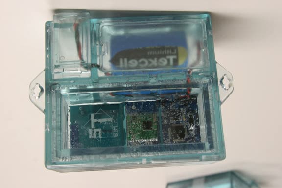
RXN610M1B01SSL
Jun 21, 2005Meter Management Information System
Equipment Class
DTS - Digital Transmission System