RXNGW1BH1025The Gateway is a device to bridge the gap of meters in the field and our server.
Transparent Technologies, Inc.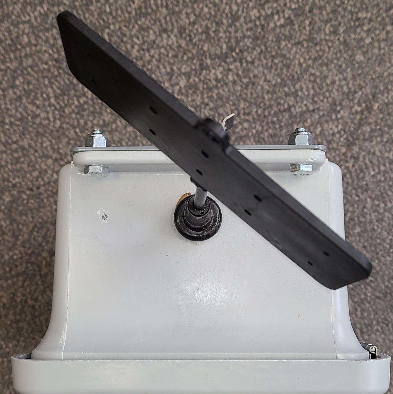
Click to zoom
Application Details
- Equipment Class
- DTS - Digital Transmission System
- Date of Grant
- May 31, 2021
- Application Purpose
- Original Equipment
- Date of Application
- May 26, 2021
- Equipment Note
- The Gateway is a device to bridge the gap of meters in the field and our server.
- Frequency Range
- 902.00000000 - 928.00000000
- Country
- United States
Documents & Files
Document Text
Text extracted from the exhibit documents filed with the FCC. Open a document above to read the original.
Users Manual
Page 1 of 9 LTE Gateway Gateway User Manual Title: Gateway User Manual Author: Chris Hack Rev: B Date: 1/31/17 NOTICE: This device complies with Part 15 of the FCC Rules [and with Industry Canada licence-exempt RSS standard(s)]. Operation is subject to the following two conditions: (1) this device may not cause harmful interference, and (2) this device must accept any interference received, including interference that may cause undesired operation. Le présent appareil est conforme aux CNR d'Industrie Canada applicables aux appareils radio exempts de licence. L'exploitation est autorisée aux deux conditions suivantes: (1) l'appareil ne doit pas produire de brouillage, et (2) l'appareil doit accepter tout brouillage radioélectrique subi, même si le brouillage est susceptible d'en compromettre le fonctionnement. Antenna Statement Under Industry Canada regulations, this radio transmitter may only operate using an antenna of a type and maximum (or lesser) gain approved for the transmitter by Industry Canada. To reduce potential radio interference to other users, the antenna type and its gain should be so chosen that the equivalent isotropically radiated power (e.i.r.p.) is not more than that necessary for successful communication. Conformément à la réglementation d'Industrie Canada, le présent émetteur radio peut fonctionner avec une antenne d'un type et d'un gain maximal (ou inférieur) approuvé pour l'émetteur par Industrie Canada. Dans le but de réduire les risques de brouillage radioélectrique à l'intention des autres utilisateurs, il faut choisir le type d'antenne et son gain de sorte que la puissance isotrope rayonnée équivalente (p.i.r.e.) ne dépasse pas l'intensité nécessaire à l'établissement d'une communication satisfaisante. Page 2 of 9 LTE Gateway Gateway User Manual Licence exempt This device complies with Industry Canada licence-exempt RSS standard(s). Operation is subject to the following two conditions: (1) this device may not cause interference, and (2) this device must accept any interference, including interference that may cause undesired operation of the device. Le présent appareil est conforme aux CNR d'Industrie Canada applicables aux appareils radio exempts de licence. L'exploitation est autorisée aux deux conditions suivantes : (1) l'appareil ne doit pas produire de brouillage, et (2) l'utilisateur de l'appareil doit accepter tout brouillage radioélectrique subi, même si le brouillage est susceptible d'en compromettre le fonctionnement. RF Exposure This equipment complies with FCC and IC RSS-102 radiation exposure limits set forth for an uncontrolled environment. This equipment should be installed and operated with the minimum distance 20cm between the radiator & human body. This radio transmitter IC: 6872A-0421GWBH has been approved by Innovation, Science and Economic Development Canada to operate with the antenna types listed below, with the maximum permissible gain indicated. Antenna types not included in this list that have a gain greater than the maximum gain indicated for any type listed are strictly prohibited for use with this device. Skywave LTE Fle Antena 15-8324-B 704~960 MHz / 1710~2155MHz VSWR ≤ 3.0 2.1 dBi Gain (nominal) Page 3 of 9 LTE Gateway Gateway User Manual The Gateway is battery powered transmitter that will be positioned outdoors to relay logs from meters in the field back to the cloud, so that the logs can be viewed and analyzed. This manual describes the basic start up for the Gateway in Debug mode to make sure everything is working correctly. Initial startup and boot sequence: First, plug the unit into the battery back, as shown in figure 1. The LCD should remain off, as shown in Figure 2. Figure 1 Figure 2 Next press the “Select” button. The LCD should say “Read SD” and then enter the Boot Menu, as shown in Figure 3. If it becomes necessary to clear a Gateway’s memory, or if the Gateway has been relocated, “Reset” should be pressed, and the instructions followed until this step (the Gateway’s LCD displays the Boot Menu prompt). Further steps are unnecessary if unneeded. If first installing the Gateway and a test of the location’s viability are desired, next press either the “Enter” or “Select” button to view the menu options. To cycle through the menu options, press “Select” and to choose a menu option, press “Enter.” Press “Enter” to select the “Boot Gateway” option when the arrow points to that option, as shown in Figure 4. Figure 3 Figure 4 The Gateway will now boot, acquiring both the local time from the cellular network and the GPS location. The Gateway will display the current operation in progress on the LCD screen, as shown in Figures 5 and 6. Figure 5 Figure 6 Page 4 of 9 LTE Gateway Gateway User Manual Once the boot process is complete, the Gateway will enter the Debug Menu, displayed in Figure 7 below. In order to cycle through the menu options, press the “Select” button. After the usage instructions, the first selectable menu option is “Listen Now.” This option initiates a two minute scan cycle where the Gateway listens for any meters it can hear and stores the data. Figure 8 displays the “Listen Now” menu option. Pressing “Enter” will select the menu option. Selecting “Listen Now” will cause the Gateway to immediately listen for any meters it can hear in the vicinity for two minutes (default) and display the number of meters found on the LCD (Figure 9). Upon completion, the LCD will display “Complete” followed by the number of meters found in the scan and then the overall number of meters stored in the Gateway’s memory. Figure 7 Figure 8 Figure 9 The second option that should be selected when installing a Gateway is the “Send EP Data” option, shown below in Figure 10. This sends the information gathered from the scan cycle to the cloud. Using this data, the user can view the meters read by the Gateway on a map in Waterscope to ensure that the current Gateway location is optimal. Figure 10 Debug Menu Options: In order to verify th…
Text truncated - open the document above for the full version.
Cover Letter(s)
5665 Airport Blvd Boulder, CO 80301 Letter of Authorization and Anti- Drug Statement Applicant Name: Transparent Technologies Address: 5665 Airport Blvd, Boulder, CO. 80301 Product Name: Gateway Model Number: T2-SYS-GTWY FCC ID: RXNGW1BH1025 We authorize: CETECOM Inc., to act on our behalf on all matters concerning the above named equipment. We declare that CETECOM Inc. is allowed to forward all information related to the approval project to the Federal Communications Commission and discuss any issues concerning the approval application. The applicant must certify that neither the applicant nor any party to the application is subject to a denial of Federal benefits, that include FCC benefits, pursuant to Section 5301 of the Anti-Drug Abuse Act of 1988, 21 U.S.C. § 862 because of a conviction for possession or distribution of a controlled substance. See 47 CFR 1.2002(b) for the definition of a "party" for these purposes. Does the applicant or authorized agent so certify? ☒ Yes I certify that I am authorized to sign this application. All of the statements herein and the exhibits attached hereto, are true and correct to the best of my knowledge and belief. In accepting a Grant of Equipment Authorization as a result of the representations made in this application, the applicant is responsible for (1) labeling the equipment with the exact FCC ID specified in this application, (2) compliance statement labeling pursuant to the applicable rules, and (3) compliance of the equipment with the applicable technical rules. If the applicant is not the actual manufacturer of the equipment, appropriate arrangements have been made with the manufacturer to ensure that production units of this equipment will continue to comply with the FCC's technical requirements. Authorizing an agent to sign this application, is done solely at the applicant's discretion; however, the applicant remains responsible for all statements in this application. If an agent has signed this application on behalf of the applicant, a written letter of authorization which includes information to enable the agent to respond to the above section 5301 (Anti-Drug Abuse) Certification statement has been provided by the applicant. It is understood that the letter of authorization must be submitted to the FCC upon request, and that the FCC reserves the right to contact the applicant directly at any time. Signature of Authorized Person Filing: Title: Embedded Systems Engineer Date: 4/21/21
Cover Letter(s)
Federal Communications Commission Equipment Authorization Division 7435 Oakland Mills Road Columbia, MD 21048 Date: 4/21/21 Subject: Request for Permanent Confidentiality FCC ID: RXNGW1BH1025 To Whom It May Concern: In accordance with §0.457(d) and §0.459 of CFR 47, and KDB 726920, Transparent Technologies hereby requests permanent confidentiality for documents filed under the following exhibit types: 1. Block Diagram 2. Schematic Diagram 3. Part List 4. Operational Description These items contain detailed system and equipment description and related information about the product which Transparent Technologies considers to be proprietary, confidential and a custom design which otherwise would not be released to the general public. Since this design is a basis from which future technological products will evolve, Transparent Technologies also feels that this information would be of benefit to its competitors, and that the disclosure of the information in these exhibits would give our competitors an unfair advantage in the market. We are aware that exhibit types cover letters, attestations, label document, test reports, RF exposure information (SAR and MPE reports), cannot be requested to be classified confidential and are thus subject to publication, as will be documents of all other exhibits types for which we have not requested a confidentiality classification. Best Regards, _______________________________ Signature Name: Brian Hulsey Title: Embedded Systems Engineer Company Name: Transparent Technologies Address: 5665 Airport Blvd, Boulder, CO. 80301
Cover Letter(s)
Federal Communications Commission Equipment Authorization Division 7435 Oakland Mills Road Columbia, MD 21048 Date: 4/21/21 Subject: Request for Short Term Confidentiality FCC-ID: RXNGW1BH1025 To Whom It May Concern: In accordance with §0.457(d) and §0.459 of CFR 47, Transparent Technologies hereby requests short term confidentiality for documents filed under the following exhibit types: 1. External Photographs 2. Internal Photographs 3. User / Instruction Manual 4. Test Set-up Photographs until the product will be publicly announced. Short term confidentiality release date / period: 180 days These items contain detailed system and equipment description and related information about the product which Transparent Technologies considers to be proprietary, confidential and a custom design which otherwise would not be released to the general public. Since this design is a basis from which future technological products will evolve, Transparent Technologies also feels that this information would be of benefit to its competitors, and that the disclosure of the information in these exhibits would give our competitors an unfair advantage in the market. We are informed and aware of our obligation that we have to inform the involved TCB in written and in due time if we intend to market the product prior to the above specified confidentiality release date so that the short term confidentiality classification can be reset prior to product launch. We are aware that exhibit types cover letters, attestations, label document, test reports, RF exposure information (SAR and MPE reports), cannot be requested to be classified confidential and are thus subject to publication, as will be documents of all other exhibits types for which we have not requested a confidentiality classification. Best Regards, ____________________________________ Signature Name: Brian Hulsey Title: Embedded Systems Engineer Company Name: Transparent Technologies Address: 5665 Airport Blvd, Boulder, CO. 80301
ID Label/Location Info
Gateway FCC Label Content: Size: FCC Label Location (Inside of Gateway lid):
RF Exposure Info
Radio Frequency Exposure Evaluation Report FOR: Transparent Technologies Model Name: T2-SYS-GTWY Product Description: The Gateway is a device to bridge the gap of meters in the field and our server. FCC ID: RXNGW1BH1025 IC ID: 6872A-0421GWBH Per: CFR Part Part1 (1.1307 &1.1310), Part 2 (2.1091), FCC KDB 447498 D01 General RF Exposure Guidance v06 ISEDC RSS-102 Issue 5 Report number: EMC_TRANS-001-21001_FCC_ISED_MPE_R2 DATE: 2021-05-25 CETECOM Inc. 411 Dixon Landing Road Milpitas, CA 95035 U.S.A. Phone: + 1 (408) 586 6200 Fax: + 1 (408) 586 6299 E-mail: [email protected] http://www.cetecom.com CETECOM Inc. is a Delaware Corporation with Corporation number: 2905571 V5.0 2015-10-27 © Copyright by CETECOM Test Report #: EMC_TRANS-001-21001_FCC_ISED_MPE_R2 FCC ID: RXNGW1BH1025 Date of Report 2021-05-25 Page 2 of 8 IC ID: 6872A-0421GWBH Page 2 of 8 1 Assessment This RF Exposure evaluation report provides evidence for compliance of the below identified device with the RF Exposure limits for mobile devices as defined in FCC CFR Part 1 (1.1307 &1.1310), Part 2 (2.1091) and IC standard RSS-102 issue 5 under worst case conditions (measured or rated RF output power, antenna gain, distance towards human body, multiple transmitter information as presented by the applicant). In addition, maximum antenna gain or minimum distance towards the human body is calculated respectively, where relevant. The device meets the limits as stipulated by the above given FCC and IC rule parts based on available specifications for worst case conditions at 20cm distance to the body. Company Description Model # Transparent Technologies The Gateway is a device to bridge the gap of meters in the field and our server. T2-SYS-GTWY Report reviewed by: TCB Evaluator 2021-05-25 Compliance Kevin Wang (Lab Manager) Date Section Name Signature Responsible for the Report: 2021-05-25 Compliance Yuchan Lu (Test Engineer) Date Section Name Signature Test Report #: EMC_TRANS-001-21001_FCC_ISED_MPE_R2 FCC ID: RXNGW1BH1025 Date of Report 2021-05-25 Page 3 of 8 IC ID: 6872A-0421GWBH Page 3 of 8 2 Administrative Data 2.1 Identification of the Testing Laboratory Issuing the Test Report Company Name: CETECOM Inc. Department: Compliance Street Address: 411 Dixon Landing Road City/Zip Code Milpitas, CA 95035 Country USA Telephone: +1 (408) 586 6200 Fax: +1 (408) 586 6299 Lab Manager: Kevin Wang Responsible Project Leader: Akanksha Baskaran 2.2 Identification of the Client / Manufacturer Client’s Name: Transparent Technologies Street Address: 5665 Airport Blvd City/Zip Code Boulder, CO 80301 Country USA 2.3 Identification of the Manufacturer Manufacturer’s Name: Same as Client Manufacturers Address: City/Zip Code Country Test Report #: EMC_TRANS-001-21001_FCC_ISED_MPE_R2 FCC ID: RXNGW1BH1025 Date of Report 2021-05-25 Page 4 of 8 IC ID: 6872A-0421GWBH Page 4 of 8 3 Equipment under Assessment Marketing name: VN Gateway HW Version : v1.1.2 SW Version : v1.10 Hardware Version Identification Number (HVIN): T2-SYS-GTWY Product Marketing Name (PMN): VN Gateway Regulatory Band: Cellular Module: LTE BAND 4: 1717.5 ~ 1747.5 MHz LTE BAND 13: 779.5 ~ 784.5 MHz ISM: Nominal band: 903 MHz – 927 MHz; Center to center: 903 MHz (ch 0) – 927 MHz (ch 23), 24 channels Integrated Module Info: LTE Module name: Telit Module number: LE910-SVL FCC/IC ID: RI7LE910SVL / 5131A-LE910SVL ISM Module name: SemTech Module number: SX1232IMLTRT GPS Module name: Telit Module number: SE873 Antenna Type: Cellular, ISM: Skywave LTE Fle Antena 15-8324-B 704~960 MHz /1710~2155MHz VSWR ≤ 3.0 2.1 dBi Gain (nominal) Maximum Conducted Output Power: Cellular: From modular grant [Watts]: LTE Band 4: 0.194 LTE Band 13: 0.170 ISM: From measurement [Watts]: 0.033 Test Report #: EMC_TRANS-001-21001_FCC_ISED_MPE_R2 FCC ID: RXNGW1BH1025 Date of Report 2021-05-25 Page 5 of 8 IC ID: 6872A-0421GWBH Page 5 of 8 Power Supply/ Rated Operating Voltage Range: Low 3.0 VDC, Nominal 3.6 VDC, High 3.7 VDC Operating Temperature Range: Low -10⁰C, Nominal 20⁰C, High 50⁰C Sample Revision: Prototype Unit; Production Unit; Pre-Production Test Report #: EMC_TRANS-001-21001_FCC_ISED_MPE_R2 FCC ID: RXNGW1BH1025 Date of Report 2021-05-25 Page 6 of 8 IC ID: 6872A-0421GWBH Page 6 of 8 4 RF Exposure Limits and FCC and IC Basic Rules For the specific described radio apparatus the following basic limits and rules apply for both, FCC and IC where not indicated differently. 4.1 Power Density Limits acc. to FCC 1.1310(e) / RSS-102 i5, cl. 4: FCC Frequency Range (MHz) Power density (mW/cm 2 ) Averaging time (minutes) 300 – 1500 f (MHz) /1500 30 1500 – 100000 1.0 30 IC 300 – 6000 0.02619 x f (MHz) 0.6834 6 4.2 Routine Environmental Evaluation Categorical Exclusion Limits acc. to FCC 2.1091(c) / RSS-102, cl. 2.5 (rounded to 1 decimal point): FCC operating frequency < 1.5GHz: excluded if ERP < 1.5W / 31.8dBm (EIRP: 33.9 dBm); operating frequency > 1.5GHz: excluded if ERP < 3.0W / 34.8dBm (EIRP: 36.9 dBm); IC 300MHz < = operating frequency < 6 GHz: excluded if EIRP < 0.0131 x f (MHz) 0.6834 W 4.3 RF Exposure Estimation (MPE Estimation) Having available the source based average output power and peak antenna gain or the ERP/EIRP of the specified device and for a known minimum distance of its radiating structures from the body of persons according to its use cases (at least 20cm) the power density at that distance can be estimated by the following formula for plane-wave equivalent conditions (far-field conditions), when ground reflection is neglected. 2 4R PG S where: S = power density (mW/cm 2 or W/m 2 ) P = power input to the antenna (mW or W) G = power gain of the antenna in the direction of interest relative to an isotropic radiator R = distance to the center of radiation of the antenna (cm or m) Test Report #: EMC_TRANS-001-21001_FCC_ISED_MPE_R2 FCC ID: RXNGW1BH1025 Date of Report 2021-05-25 Page 7 of 8 IC ID: 6872A-0421GWBH Page 7 of 8 5 Evaluations 5.1 Analysis …
Text truncated - open the document above for the full version.
Test Report
A2LA Accredited IC recognized # 3462B-2 CABID: US0187 CETECOM Inc. 411 Dixon Landing Road Milpitas, CA 95035 U.S.A. Phone: + 1 (408) 586 6200 Fax: + 1 (408) 586 6299 E-mail: [email protected] http://www.cetecom.com CETECOM Inc. is a Delaware Corporation with Corporation number: 2905571 V4.0 2012-07-25 © Copyright by CETECOM FCC / ISED Test Report FOR: Transparent Technologies Model Name: T2-SYS-GTWY Product Description: The Gateway is a device to bridge the gap of meters in the field and our server. FCC ID: RXNGW1BH1025 IC ID: 6872A-0421GWBH Applied Rules and Standards: 47 CFR Part 15.247 (DTS) RSS-247 Issue 2 (DTS) & RSS-Gen Issue 5 REPORT #: EMC_TRANS-001-21001_15.247_ISM_DTS_R2 DATE: 2021-05-25 Test Report #: EMC_TRANS-001-21001_15.247_ISM_DTS_R2 FCC ID: RXNGW1BH1025 Date of Report 2021-05-25 IC ID: 6872A-0421GWBH TABLE OF CONTENTS 1 ASSESSMENT ...................................................................................................................................................................................... 3 2 ADMINISTRATIVE DATA ...................................................................................................................................................................... 4 2.1 IDENTIFICATION OF THE TESTING LABORATORY ISSUING THE EMC TEST REPORT ................................................................................... 4 2.2 IDENTIFICATION OF THE CLIENT ............................................................................................................................................................ 4 2.3 IDENTIFICATION OF THE MANUFACTURER .............................................................................................................................................. 4 3 EQUIPMENT UNDER TEST (EUT) ....................................................................................................................................................... 5 3.1 EUT SPECIFICATIONS ......................................................................................................................................................................... 5 3.2 EUT SAMPLE DETAILS ......................................................................................................................................................................... 6 3.3 TEST SAMPLE CONFIGURATION ............................................................................................................................................................ 6 3.4 JUSTIFICATION FOR WORST CASE MODE OF OPERATION ....................................................................................................................... 7 4 SUBJECT OF INVESTIGATION ........................................................................................................................................................... 7 5 MEASUREMENT RESULTS SUMMARY .............................................................................................................................................. 7 6 MEASUREMENT UNCERTAINTY ........................................................................................................................................................ 8 6.1 ENVIRONMENTAL CONDITIONS DURING TESTING: .................................................................................................................................. 8 6.2 DATES OF TESTING: ............................................................................................................................................................................ 8 7 MEASUREMENT PROCEDURES ......................................................................................................................................................... 9 7.1 RADIATED MEASUREMENT ................................................................................................................................................................... 9 7.2 RF CONDUCTED MEASUREMENT PROCEDURE .................................................................................................................................... 11 8 TEST RESULT DATA .......................................................................................................................................................................... 12 8.1 MAXIMUM PEAK CONDUCTED OUTPUT POWER ................................................................................................................................... 12 8.2 POWER SPECTRAL DENSITY .............................................................................................................................................................. 16 8.3 DUTY CYCLE ..................................................................................................................................................................................... 20 8.4 BAND EDGE COMPLIANCE .................................................................................................................................................................. 21 8.5 EMISSION BANDWIDTH 6 DB AND 99% OCCUPIED BANDWIDTH ............................................................................................................ 27 8.6 RADIATED TRANSMITTER SPURIOUS EMISSIONS AND RESTRICTED BANDS ............................................................................................ 34 9 TEST SETUP PHOTOS ....................................................................................................................................................................... 47 10 TEST EQUIPMENT AND ANCILLARIES USED FOR TESTING ....................................................................................................... 47 11 REVISION HISTORY ........................................................................................................................................................................... 48 Te…
Text truncated - open the document above for the full version.
Test Setup Photos
CETECOM Inc. 411 Dixon Landing Road Milpitas, CA 95035 U.S.A. Phone: + 1 (408) 586 6200 Fax: + 1 (408) 586 6299 E-mail: [email protected] http://www.cetecom.com CETECOM Inc. is a Delaware Corporation with Corporation number: 2905571 FCC / ISED Test Setup Photos FOR: Transparent Technologies Model Name: T2-SYS-GTWY Product Description: The Gateway is a device to bridge the gap of meters in the field and our server. FCC ID: RXNGW1BH1025 IC ID: 6872A-0421GWBH Addition to Report #: EMC_TRANS-001-21001_FCC_27_ISED_R1 EMC_TRANS-001-21001_15.247_ISM_DTS_R2 DATE: 2021-05-24 Page 2 of 9 Radiated Measurements 9 KHz to 30 MHz Page 3 of 9 30 MHz to 1 GHz Page 4 of 9 1 GHz to 3GHz Page 5 of 9 3 GHz to 18GHz Page 6 of 9 Conducted Measurements Page 7 of 9 Frequency Stability Page 8 of 9 EUT Photos Top view Conducted sample Side view Side view Page 9 of 9 Revision History Date Report Name Changes to report Report prepared by 2021-04-13 EMC_TRANS-001-21001_Setup_Photos_R1 Initial Version Yuchan Lu 2021-05-24 EMC_TRANS-001-21001_Setup_Photos_R2 Updated the related reports name Yuchan Lu <<The End>>
Contact Information
Applicant
Brian Hulsey
Test Firm
CETECOM Inc.Meinolf Glunz
[email protected]408-586-6301
Technical Specifications
| # | Rule Parts | Frequency Range | Power Output |
|---|---|---|---|
| 1 | 15C | 902 MHz - 928 MHz | 31.00 mW |
Other Applications from Transparent Technologies, Inc.
RXN1M2ESS
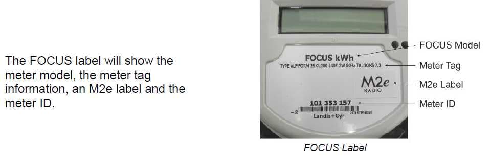
Nov 11, 2012Models AL & AX Landis & Gyr FOCUS Electric Meters with M2e Radio
Equipment Class
DTS - Digital Transmission System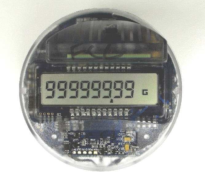
RXN10RR1
Dec 26, 2010Electronic register with embedded M2 radio
Equipment Class
DTS - Digital Transmission System
RXN1207R2SSL
Jan 22, 2008R2 Utility Radio Transceiver
Equipment Class
DTS - Digital Transmission System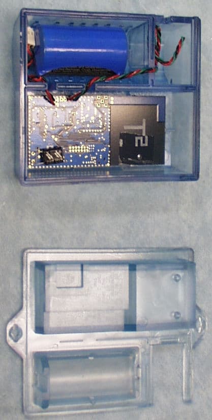
RXN610M2SSL
Sep 17, 2007M2 Utility Radio Transceiver
Equipment Class
DXT - Part 15 Low Power Transceiver, Rx Verified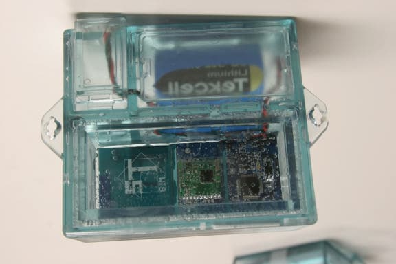
RXN610M1B01SSL
Jun 21, 2005Meter Management Information System
Equipment Class
DTS - Digital Transmission System