RXN610M1B01SSLMeter Management Information System
Transparent Technologies, Inc.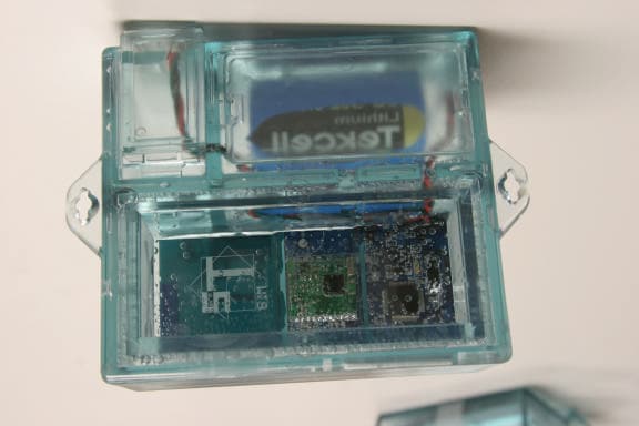
Click to zoom
Application Details
- Equipment Class
- DTS - Digital Transmission System
- Date of Grant
- Jun 21, 2005
- Application Purpose
- Original Equipment
- Date of Application
- Jun 21, 2005
- Equipment Note
- Meter Management Information System
- Frequency Range
- 919.59000000 - 920.00000000
- Country
- United States
Documents & Files
Document Text
Text extracted from the exhibit documents filed with the FCC. Open a document above to read the original.
Users Manual
TRANSPARENT TECHNOLOGIES M1B Utility Radio Transmitter Operations Manual Transparent Technologies, Inc 5665 Airport Blvd Boulder, CO 80301 720-406-1294 Disclaimer In no event shall Transparent Technologies be liable for any incidental, indirect, or consequential damages or other damages including without limitation loss of profits, loss of revenue, loss of data, loss of use of the product or any associated equipment, downtime, and user’s time associated with the use of this product, the resale hardware or its software. Use of Hardware In no event shall Transparent Technologies be liable for damages resulting from the use of its hardware or the malfunction of that hardware. Specifications for the hardware are subject to change at any time without notice. Copyrights /Trademarks Transparent Technologies reserves the names T2, M1 and UDA. References are made to Sony®, Clie™and Palm©. Version M1B Version 1.00a May 2005 M1B Utility Radio Transmitter Operations Manual OVERVIEW 1 INSTALLATION & WIRING 2 OPERATION 3 BATTERY 4 APPENDIX 5 1 OVERVIEW M1B Utility Radio Transmitter Univeral Basic Specifications The M1 radio is a universal AMR device designed for every utility. Encoder and digital inputs for all major water meter registers. Transmission: One-Way DTS (unregulated) Regulatory: FCC 15.247 Simple Temperature: -40°F to 158°F The M1 operates in an unlicensed mode in the 900-Mhz range which requires no utility regulation. The radio is easily configured and interfaced with an off-the-shelf PDA. (-40°C to +70°C) Humidity: 100% Submersion: IP-68 Rating Packaging: PCB 100% Powerful encapsulated In addition to reliable meter reading, the M1 also provides powerful datalogging, consumption profiling and leak detection. The M1 transmit basic meter and leak detection information through the RF signal. Housing: Smoke or Clear Polycarbonate Interface: All Major Encoders All Major SC/Pulse See Compatability Battery: Replaceable 19.0 A-hr D-cell Battery Life: Up to 20 years 1 2 1 M1B Packaging The M1B is housed in a polycarbonate shell with multiple levels of waterproofing. The housing is available in either a clear or smoke tint. The housing is assembled with a UV-cure adhesive which provides the first level of environmental protection. The radio electronics are 100% encapsulated in a dielectric gel for 100% moisture protection. Finally, all cable entry/exit points are sealed with gel grommets to protect against long- term moisture penetration. The rear of the radio unit provides the access chambers for the wiring connections and the replaceable battery. The product label indicates a model number, a lot/serial number and the FCC identifier. 1 2 INSTALLATION & Installation The M1A is designed for all environments and can be installed either in indoor or outdoor environments. Mounting Orientation The most important consideration is to keep the M1B radio unit UPRIGHT when it is installed. The antenna is located on the top of the radio board and the RF transmission pattern is optimized with an upright orientation. In the UPRIGHT position: • The hanging slot is at the top of the unit • The T2 logo will be readable at the top of the housing • The battery will be at the bottom Other primary considerations for optimum transmission: • Avoid mounting the radio unit directly against metal surfaces (pipes, valves, etc.) In all cases, the installer should experiment with mounting techniques and RF performance prior to quantity installation. • Avoid mounting the unit below typical water levels. • Do NOT drive screws or mounting hardware into the unit’s plastic housing. • Always mount the unit at the highest grade possible. 2 2 Pit & Vault Installations For best transmission, the unit should not be mounted directly on any metal surfaces, such as pipes or valves, or mounted below know water levels. The M1B has multiple mounting options, including a slot for wire ties which can be used to hang the M1A, attach on a plastic stake or screw directly onto a wall. An effective mounting technique for commercial meter vaults is to hang the M1A unit from a fixture (such as a ladder rung or the lid itself) near the top of the vault. Proper mounting in these types of vaults is essential for good RF performance. For smaller vaults and meter boxes, a variety of acceptable mounting options are available. Two simple methods are hanging from the lid/cover and staking into the ground. If time and space are available, the M1A can also be mounted on the side of a pit with a wall bracket. For vaults or pits with metals lids, the M1B should be optimally mounted 6-18 inches below the lid/cover. 3 2 Indoor & Wall Installations For best transmission, the unit should not be mounted backing on metal surfaces, reinforced concrete or other dense surfaces. In indoor mounting situations, a higher mounting site will improve RF performance. In below grade sites (e.g. basements), the installer should experiment with the best location before the final mounting. In these instances, the direction/bearing of the receiver should be considered. For instance, if a unit is to be mounted in a basement with reinforced concrete walls, the best mounting location could be on the opposite wall, although this increases the overall distance. 4 2 Wiring Encoders As a default communication The M1B utilizes the ECR-II communications defacto-standard wiring conventions for encoder interfaces: Red: Clock/PWR Green: Data Black: Ground This wiring convention should be consistent with all Metron-Farnier, ECR-II and ECR-III registers. The unit can be ordered with a pre- wired cable in 5-ft increments. In this case, the cable with leads will exit on the side or bottom of the unit. For field retrofit applications, the unit can be ordering with leads ready for splicing in the wiring chamber. Wire Connections The wiring connections are critical for reliable radio-to-register communications. T2 recommends the use of 3m gel- cap type terminations. These connectors and the crimping to…
Text truncated - open the document above for the full version.
Cover Letter(s)
Item 1. Please provide a valid general agreement in the name of the applicant. Note to item 1: CKC CS will provide in a separate email an updated General Agreement. From: IAL Date: 6/22/05 Response: Signed GA provided CKC CS: Item 2. Please provide a Block Diagram in accordance with 2.1033(b)(5) which includes all frequencies used in the device. From: IAL Date: 6/22/05 Response: Exhibit provided. CKC CS:
External Photos
External Photos:
Internal Photos
Internal Photos:
Test Report
EMC EMISSIONS - TEST REPORT (FULL) Test Report No. BC500220-1 Issue Date: May 17, 2005 Model / Serial No. M1B / 2513 Product Type Utility Automated Meter Reading Radio Client Metron Farnier Manufacturer Transparent Technologies License holder Transparent Technologies 5665 Airport Blvd Address Boulder, CO 80301 Test Criteria Applied FCC CFR47 Part 15.247 Test Result PASS Test Project Number References BC500220-1 Total Pages Including Appendices: 38 Title 47 CFR 15: RADIO FREQUENCY DEVICES Reviewed By : Approved By : INTERNATIONAL APPROVALS LABORATORIES (IAL) reports apply only to the specific samples tested under stated test conditions. It is the manufacturer's responsibility to assure that additional production units of this model are manufactured with identical electrical and mechanical components. IAL have no liability for any deductions, inferences or generalizations drawn by the client or others from IAL issued reports. This report is the confidential property of the client. As a mutual protection to our clients, the public and ourselves, extracts from the test report shall not be reproduced except in full without our written approval of IAL. This report shall not be used by the client to claim product endorsement by NVLAP (No. 200624- 0) or any agency of the US government. International Approval Laboratories and its professional staff hold government and professional organization certifications and are members of IEEE, NVLAP, and VCCI. Lab Code:200264-0 Project File: BC500220 Page 2 of 38 International Approvals Laboratories, LLC 5541 Central Avenue, Suite 110 Boulder, Colorado 80301 Voice: 303 786 7999 Fax: 303 449 6160 Rev.No 1 D I R E C T O R Y Documentation Page(s) Test report 1 - 38 Directory 2 Test Regulations 3 - 4 General Remarks 4 - 5 Test-setup Photographs 6 - 9 Appendix A Test Data Sheets and Test Equipment Used 10 - 27 Appendix B Test Plan/Constructional Data Form 28 - 33 Appendix C Measurement Protocol/Test Procedures 34 - 38 STATEMENT OF MEASUREMENT UNCERTAINTY The data and results referenced in this document are true and accurate. The measurement uncertainty for Conducted Emissions in the frequency range of 150kHz – 30MHz is calculated to be ±2.30dB and for Radiated Emissions is calculated to be ±3.60dB in the frequency range of 30MHz – 200MHz and ±3.38dB in the frequency range of 200MHz – 1000MHz. EUT Received Date: 29-April-2005 Testing Start Date: 29-April-2005 Testing End Date: 3-May-2005 Project File: BC500220 Page 3 of 38 International Approvals Laboratories, LLC 5541 Central Avenue, Suite 110 Boulder, Colorado 80301 Voice: 303 786 7999 Fax: 303 449 6160 Rev.No 1 The tests were performed according to following regulations : 1. FCC CFR47 Part 15.205 2. FCC CFR47 Part 15.207 3. FCC CFR47 Part 15.209 4. FCC CFR47 Part 15.247 5. ICES-003 Emission Test Results: Conducted Emissions, Powerline (15.207) - Not Applicable Test Result Minimum limit margin NA dB at NA MHz Maximum limit exceeding dB at MHz Remarks: Radiated Emissions (15.209) - PASS Test Result Minimum limit margin -2.0 dB at 0.06 MHz Maximum limit exceeding dB at MHz Remarks: Bandwidth 15.247 (a)(2) - PASS Test Result Remarks: The 6dB was measured to be 585kHz Peak Output Power 15.247 (b)(3) - PASS Test Result Minimum limit margin -16.3 dB at 920.0 MHz Maximum limit exceeding dB at MHz Remarks: Radiated Emissions 15.205/15.247(c) - PASS Test Result Minimum limit margin -8.6 dB at 2760.04 MHz Maximum limit exceeding dB at MHz Remarks: Project File: BC500220 Page 4 of 38 International Approvals Laboratories, LLC 5541 Central Avenue, Suite 110 Boulder, Colorado 80301 Voice: 303 786 7999 Fax: 303 449 6160 Rev.No 1 Spectral Density 15.247(d) - PASS Test Result Remarks: Maximum measured value = 6.66dBm/delta from the limit = -1.34 GENERAL REMARKS: The following remarks are to be considered as “where applicable“ and are taken into account while completing any FCC/IC/ETSI radio tests at International Approvals Laboratories, LLC. Testing was performed in 3 different orthogonal axis to determine the worst case emissions from the device. The worst case emissions measurements are shown in this report. FCC CFR47 Part 15.31: Measurement Standards: In any case where the device is powered off a battery, a fresh battery was used during test. In cases where the device is powered off an AC supply, voltage was varied per Part 15.31 to find worst case emissions. FCC CFR47 Part 15.35: Measurement Detector Functions and Bandwidths: FCC Part 15.35 was utilized when performing the measurements within this report. In any case where the device is powered off a battery, a fresh battery was used during test. In cases where the device is powered off an AC supply, voltage was verified per Part 15.31 to find worst case emissions. The actual test distance for the FCC Part 15.209 testing was conducted at 10m for the fact that the device was being tested to EN55022 Class B from 30 MHz to 1000 MHz (meets/exceeds the FCC Part 15.209 & 109B limits) The data is automatically extrapolated back to the FCC 3m limits and measurements are corrected to better show the compliance to FCC requirements and reduce confusion. A correction factor of 10.54dB is used in cases of 30MHz and up for a difference between 10m and 3m measurement distances. All measurements that are lesser than 30MHz where applicable are accompanied with the fall of measurements and calculations to support the interpolation. Modifications required to pass: Test Specification Deviations: Additions to or Exclusions from Project File: BC500220 Page 5 of 38 International Approvals Laboratories, LLC 5541 Central Avenue, Suite 110 Boulder, Colorado 80301 Voice: 303 786 7999 Fax: 303 449 6160 Rev.No 1 Required Information In Accordance to FCC CFR 47 Part 2.1033: Exhibits Including (where applicable): 1. Users Manual 2. Operation Description 3. Block Diagram 4. Report of Measurement 5. External & Internal Photographs 6. Schematic 7. Parts List 8. Tuning Procedure (if applicable) 9. Test Setup…
Text truncated - open the document above for the full version.
Test Setup Photos
Project File: BC500220 Page 7 of 38 International Approvals Laboratories, LLC 5541 Central Avenue, Suite 110 Boulder, Colorado 80301 Voice: 303 786 7999 Fax: 303 449 6160 Rev.No 1 Test-setup photo(s): Radiated Intentional/Unintentional Emissions Project File: BC500220 Page 8 of 38 International Approvals Laboratories, LLC 5541 Central Avenue, Suite 110 Boulder, Colorado 80301 Voice: 303 786 7999 Fax: 303 449 6160 Rev.No 1 Test-setup photo(s): Radiated Intentional/Unintentional Emissions Project File: BC500220 Page 9 of 38 International Approvals Laboratories, LLC 5541 Central Avenue, Suite 110 Boulder, Colorado 80301 Voice: 303 786 7999 Fax: 303 449 6160 Rev.No 1 Test-setup photo(s): Conducted Port Emissions
Contact Information
Applicant
Brian Hulsey
Technical Contact
Transparent Technologies, Inc.Duane Switzer
303-217-5995
2005 10th Street · Boulder, Colorado · United States
Non-Technical Contact
Transparent Technologies, Inc.Rachel Welsh
303-217-5995
Test Firm
International Approval Laboratories, LLCTodd Seeley
Technical Specifications
| # | Rule Parts | Frequency Range | Power Output |
|---|---|---|---|
| 1 | 15C | 919.59 MHz - 920 MHz | 23.00 mW |
Other Applications from Transparent Technologies, Inc.
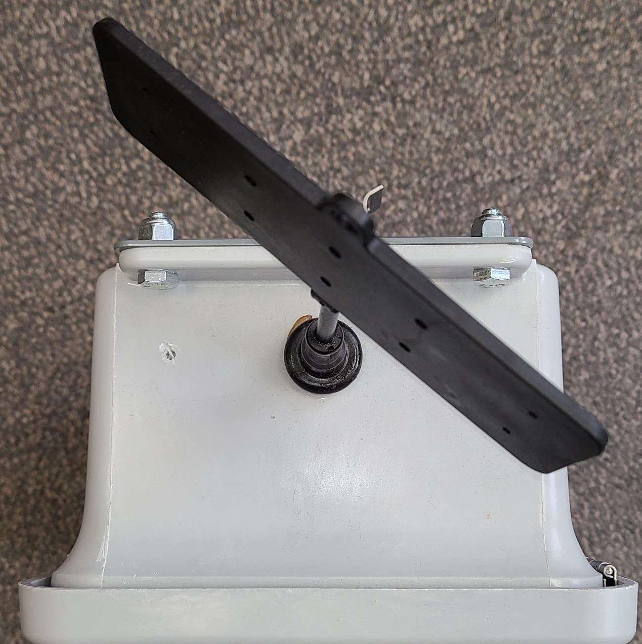
RXNGW1BH1025
May 31, 2021The Gateway is a device to bridge the gap of meters in the field and our server.
Equipment Class
DTS - Digital Transmission System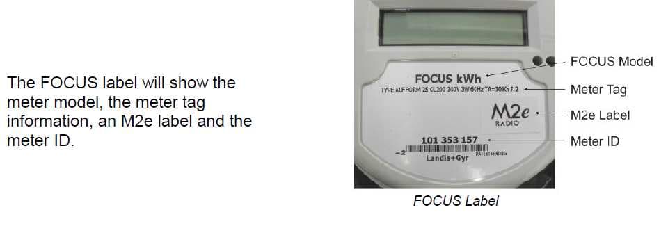
RXN1M2ESS
Nov 11, 2012Models AL & AX Landis & Gyr FOCUS Electric Meters with M2e Radio
Equipment Class
DTS - Digital Transmission System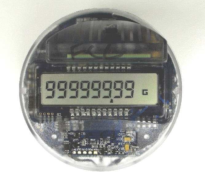
RXN10RR1
Dec 26, 2010Electronic register with embedded M2 radio
Equipment Class
DTS - Digital Transmission System
RXN1207R2SSL
Jan 22, 2008R2 Utility Radio Transceiver
Equipment Class
DTS - Digital Transmission System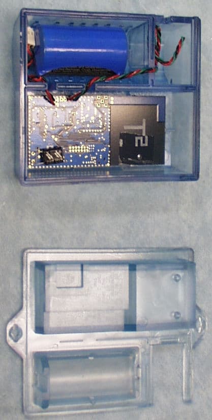
RXN610M2SSL
Sep 17, 2007M2 Utility Radio Transceiver
Equipment Class
DXT - Part 15 Low Power Transceiver, Rx Verified