RXN610M101SSM1 Utility Radio Transmitter
Transparent Technologies, Inc.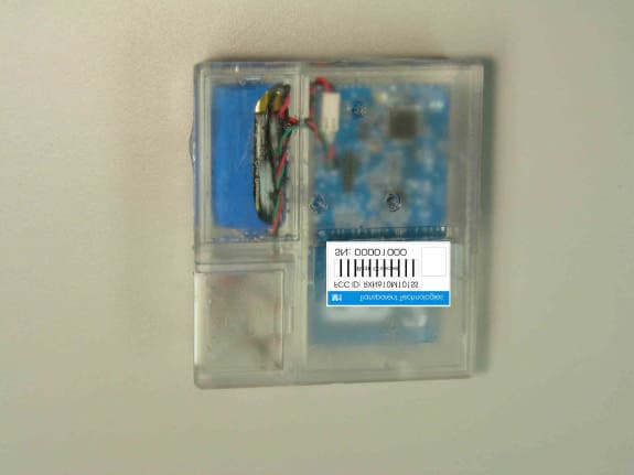
Click to zoom
Application Details
- Equipment Class
- DXX - Part 15 Low Power Communication Device Transmitter
- Date of Grant
- Jun 09, 2004
- Application Purpose
- Original Equipment
- Date of Application
- Jun 09, 2004
- Equipment Note
- M1 Utility Radio Transmitter
- Frequency Range
- 919.80000000 - 919.80000000
- Country
- United States
Documents & Files
Document Text
Text extracted from the exhibit documents filed with the FCC. Open a document above to read the original.
Users Manual
M M 1 1 Utility Radio Transmitter M1 Utility Radio Transmitter Preliminary Documentation Transparent Technologies, Inc. www.transparenttech.com M M 1 1 Utility Radio Transmitter Transparent Technologies introduces a simple, cost-effective utility radio. The M1 radio is a one-way transmitter which requires no field configuration and is compatible with existing utility systems. The M1 operates in an unlicensed mode in the 900-Mhz range which requires no utility regulation. SPECIFICATIONS Transmission: Base Mode Only Regulatory: FCC Section 15.249 Temperature: -40°F to 158°F (-40°C to +70°C) Humidity: 100% Submersion: IP-68 Rating Packaging: PCB and Connectors 100% Gel-encapsulated Modified ABS-Marine Housing Meter Interface: 3-Wire Encoder (ECR-II protocol) Battery: Replaceable Thionyl-Chloride Lithium 8.5 A-hr C-cell Battery Life: 10 Years + Transparent Technologies, Inc. www.transparenttech.com M M 1 1 Utility Radio Transmitter INSTALLATION THIS END UP The M1 can be installed either in indoor or outdoor environments. The unit is 100% waterproof. The M1 should always be installed vertically. The backside of the unit indicates the proper orientation. For best transmission, the unit should not be mounted directly on any metal surfaces, such as pipes or valves. If mounting in a pit or vault, the unit should be at least 8 inches below the lid. WIRING The M1 utilizes the defacto-standard ECR-II communications protocol and standard wiring conventions Red: Clock/PWR Green: Data Black: Ground The unit can be ordered with a pre-wired cable in 5-ft increments or with leads ready for splicing in the wiring chamber. Transparent Technologies, Inc. www.transparenttech.com Wiring Chamber Cable Exit M M 1 1 Utility Radio Transmitter GENERAL OPERATIONS Initial Mode Initial mode at startup is sleep mode. Start Radio To start the radio, briefly position magnet on marker on the front (see diagram). A general sweep from top to bottom across the marker will work best. All subsequent positioning of the magnet on marker will force an immediate read of the MIU. Soft Reset Holding the magnet on the marker for 10 seconds or more will cause a soft reset of the radio. The initial state after a soft reset will be sleep mode. The unit will need to be started as above. Front View of M1 Marke r LEDs Force MIU Read Positioning of a magnet on the marker for anything less than 10 seconds will force a new read of the MIU. LED Indicators Green LED will flash during every radio transmission. This will only take place for one minute after a Radio Start and/or a Force MIU Read. Red LED will flash during every radio transmission that has a tamper count (a failure to obtain an error-free reading of the MIU). This will only take place for one minute after a Radio Start and/or a Force MIU Read. Both Green and Red LED’s On a Soft-Reset will indicate (turn on) when the 10-second reset limit has been reached. This indicator will cease when the magnet is removed. Transparent Technologies, Inc. www.transparenttech.com M M 1 1 Utility Radio Transmitter RF Transmission The M1 transmits the following data on its RF transmission: ID number Meter Reading Group Code Error Code CRC (for error checking) The M1 transmits its signal every five (5) seconds. Meter interrogation The M1 is hard-coded to interrogate the encoded register once every hour. Upon successful interrogation, the M1 will update its memory with the register’s ID and reading. Unsuccessful Transparent Technologies, Inc. www.transparenttech.com M M 1 1 Utility Radio Transmitter Appendix A – FCC Information 15.21 Information to user. - The users manual or instruction manual for an intentional or unintentional radiator shall caution the user that changes or modifications not expressly approved by the party responsible for compliance could void the user's authority to operate the equipment. 15.27 Special accessories. (a) Equipment marketed to a consumer must be capable of complying with the necessary regulations in the configuration in which the equipment is marketed. Where special accessories, such as shielded cables and/or special connectors, are required to enable an unintentional or intentional radiator to comply with the emission limits in this part, the equipment must be marketed with, i.e., shipped and sold with, those special accessories. However, in lieu of shipping or packaging the special accessories with the unintentional or intentional radiator, the responsible party may employ other methods of ensuring that the special accessories are provided to the consumer, without additional charge, at the time of purchase. Information detailing any alternative method used to supply the special accessories shall be included in the application for a grant of equipment authorization or retained in the verification records, as appropriate. The party responsible for the equipment, as detailed in §2.909 of this chapter, shall ensure that these special accessories are provided with the equipment. The instruction manual for such devices shall include appropriate instructions on the first page of the text concerned with the installation of the device that these special accessories must be used with the device. It is the responsibility of the user to use the needed special accessories supplied with the equipment. (b) If a device requiring special accessories is installed by or under the supervision of the party marketing the device, it is the responsibility of that party to install the equipment using the special accessories. For equipment requiring professional installation, it is not necessary for the responsible party to market the special accessories with the equipment. However, the need to use the special accessories must be detailed in the instruction manual, and it is the responsibility of the installer to provide and to install the required accessories. (c) Accessory items that can be readily obtained from multiple retail outlets are not considered to be special accessories and are no…
Text truncated - open the document above for the full version.
External Photos
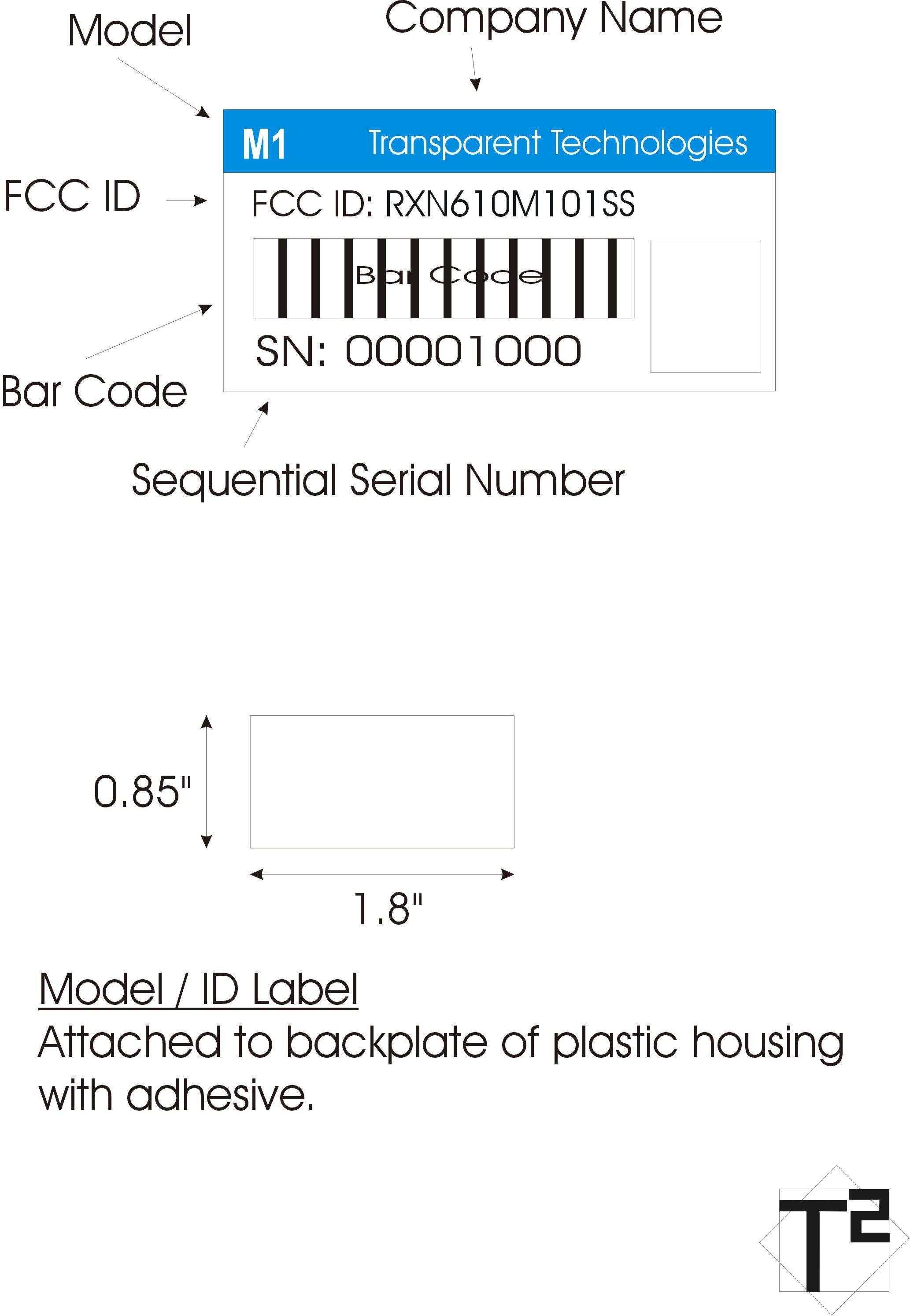
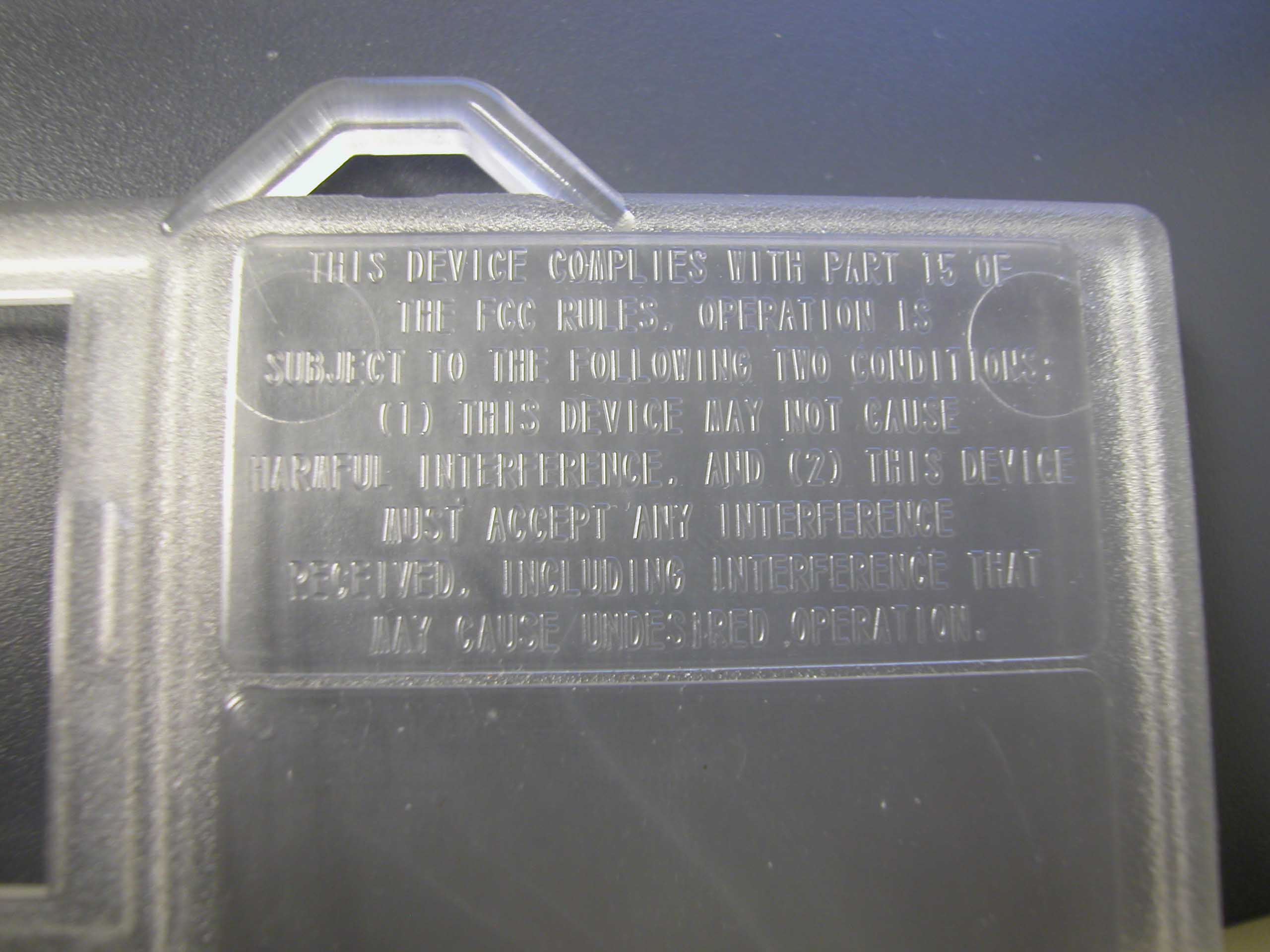
External Photos Top Side Right Side Bottom Side End Battery Other End Left Side Label Placement The Required FCC Statement is molded in the plastic directly above the label.
Internal Photos
Internal Photos Top of case removed Top of PCB Bottom of PCB
Parts List/Tune Up Info
Installation and Tune-up Instructions: A Preliminary copy of the M1 Manual (submitted under Exhibit 12) contains information on installation and field wiring for the M1 unit. Transparent Technologies, Inc. 811 South Public Road Lafayette, Colorado 80026 www.transparenttech.com
RF Exposure Info
RF Safety Calculations: Please add the RF Safety Calculations in accordance to FCC CFR47 Part 2.1091 or 2.1093 where applicable. Not Applicable Transparent Technologies, Inc. 811 South Public Road Lafayette, Colorado 80026 www.transparenttech.com
Test Report
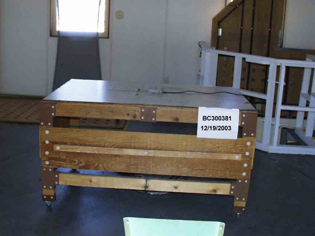
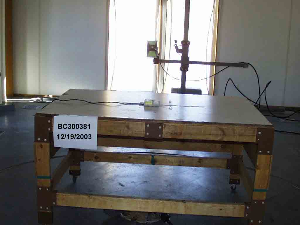
EMC EMISSIONS - TEST REPORT (Full) Test Report No. BC300381-1 Issue Date: Wed. May 26, 2004 Model / Serial No. M1 / SN: EMC1 Product Type AMR Radio Client Metron-Farnier Manufacturer Metron-Farnier License holder Metron-Farnier 5661 Airport Blvd. Suite B Address Boulder, CO 80301 Test Criteria Applied FCC CFR47 Part 15.249 Test Result PASS Test Project Number References BC300381 Total Pages Including Appendices: 24 Title 47 CFR 15: RADIO FREQUENCY DEVICES Reviewed By : Approved By : INTERNATIONAL APPROVALS LABORATORIES (IAL) reports apply only to the specific samples tested under stated test conditions. It is the manufacturer's responsibility to assure that additional production units of this model are manufactured with identical electrical and mechanical components. IAL have no liability for any deductions, inferences or generalizations drawn by the client or others from IAL issued reports. This report is the confidential property of the client. As a mutual protection to our clients, the public and ourselves, extracts from the test report shall not be reproduced except in full without our written approval of IAL. This report shall not be used by the client to claim product endorsement by NVLAP (No. 200624- 0) or any agency of the US government. International Approval Laboratories and its professional staff hold government and professional organization certifications and are members of IEEE, NVLAP, and VCCI. Project File: BC300381 Page 2 of 24 International Approvals Laboratories, LLC 5541 Central Avenue, Suite 110 Boulder, Colorado 80301 Voice: 303 786 7999 Fax: 303 449 6160 Rev.No 1 D I R E C T O R Y Documentation Page(s) Test report 1 - 24 Directory 2 Test Regulations 3 - 6 General Remarks 5 Test-setup Photographs 7 - 10 Appendix A Test Data Sheets and Test Equipment Used 11 - 18 Appendix B Test Plan/Constructional Data Form 19 - 19 Appendix C Measurement Protocol/Test Procedures 20 - 24 STATEMENT OF MEASUREMENT UNCERTAINTY The data and results referenced in this document are true and accurate. The measurement uncertainty for Conducted Emissions in the frequency range of 150kHz – 30MHz is calculated to be ±2.30dB and for Radiated Emissions is calculated to be ±3.60dB in the frequency range of 30MHz – 200MHz and ±3.38dB in the frequency range of 200MHz – 1000MHz. EUT Received Date: 19-Dec -2003 Testing Start Date: 19-Dec-2003 Testing End Date: 19-Dec -2003 Project File: BC300381 Page 3 of 24 International Approvals Laboratories, LLC 5541 Central Avenue, Suite 110 Boulder, Colorado 80301 Voice: 303 786 7999 Fax: 303 449 6160 Rev.No 1 The tests were performed according to following regulations: 1. FCC CFR47 Part 15.207 2. FCC CFR47 Part 15.209 3. FCC CFR47 Part 15.249 Emission Test Results: Conducted Emissions, Powerline - 15.207 - (Not Applicable) Test Result Minimum limit margin dB at MHz Maximum limit exceeding dB at MHz Remarks: Conducted Emissions, Data I/O (Ethernet, RJ11, etc.) - (Not Applicable) Test Result Minimum limit margin dB at MHz Maximum limit exceeding dB at MHz Remarks: Radiated Emissions (Electric Field) - 15.209 - PASS Test Result Minimum limit margin 8.4 dB at 10000 MHz Maximum limit exceeding dB at MHz Remarks: Fundamental Field Strength Measurement Radiated Emissions (Electric Field) - 15.249(a) - PASS Test Result Minimum limit margin 10.60 dB at 0920.01 MHz Maximum limit exceeding dB at MHz Remarks: Radiated Emissions outside Frequency Band Radiated Emissions (Electric Field) - 15.249(c) - PASS Test Result Minimum limit margin 20.60 dB at 2760.00 MHz Maximum limit exceeding dB at MHz Remarks: Project File: BC300381 Page 4 of 24 International Approvals Laboratories, LLC 5541 Central Avenue, Suite 110 Boulder, Colorado 80301 Voice: 303 786 7999 Fax: 303 449 6160 Rev.No 1 Average Measurements for Emissions >1GHz Radiated Emissions (Electric Field) - 15.249(d) - PASS Test Result Minimum limit margin 5.20 dB at 1840.06 MHz Maximum limit exceeding dB at MHz Remarks: CW mode was selected for the fact that it gives the worst case measurement. Project File: BC300332 Page 5 of 19 International Approvals Laboratories, LLC 5541 Central Avenue, Suite 110 Boulder, Colorado 80301 Voice: 303 786 7999 Fax: 303 449 6160 Rev.No 1 GENERAL REMARKS: Testing was performed in 3 different orthoganal axis to determine the worste case emissions from the device. The worste case emissions measurements are shown in this report. In any case where the device is powered off a battery, a fresh battery was used durring test. In cases where the device is powered off an AC supply, voltage was veried per Part 15.31 to find worst case emissions. The testing herein was completed on 2 separate dates (January 2004 & May 2004). The 15.249 was completed without gel and with gel around the PCB per the clients’ request. All the 15.209 data and the 99%bandwidth were retested. However, since there was no difference with the test 15.209 and the 99% bandwidth results from January 2004 & May 2004, the January 2004 data has been left in this report. The data herein is worst case from a gelled unit to a non gelled unit. The worst case is without gel. (With gel; the signals are attenuated from 20- 30dB than what is shown in this report.). Unintenational emissions testing was completed from 26MHz and up. No emissions were detected between 26 and 30 MHz. Modifications required to pass: NONE Test Specification Deviations: NONE Project File: BC300381 Page 6 of 24 International Approvals Laboratories, LLC 5541 Central Avenue, Suite 110 Boulder, Colorado 80301 Voice: 303 786 7999 Fax: 303 449 6160 Rev.No 1 Required Information In Accordance to FCC CFR 47 Part 2.1033: Exhibits Including (where applicable): 1. Users Manual 2. Operation Description 3. Block Diagram 4. Report of Measurement 5. External & Internal Photographs 6. Schematic 7. Parts List 8. Tuning Procedure (if applicable) 9. Test Setup Photograph 10. Label Drawings and or Photograpghs 11. Description of Support Equipment (where Applicable) Required Information i…
Text truncated - open the document above for the full version.
Contact Information
Applicant
Brian Hulsey
Technical Contact
Transparent Technologies, Inc.Duane Switzer
303-217-5995
2005 10th Street · Boulder, Colorado · United States
Non-Technical Contact
Transparent Technologies, Inc.Rachel Welsh
303-217-5995
Test Firm
International Approval Laboratories, LLCTodd Seeley
Technical Specifications
| # | Rule Parts | Frequency Range | Power Output |
|---|---|---|---|
| 1 | 15C | 919.8 MHz - 919.8 MHz | - |
Other Applications from Transparent Technologies, Inc.
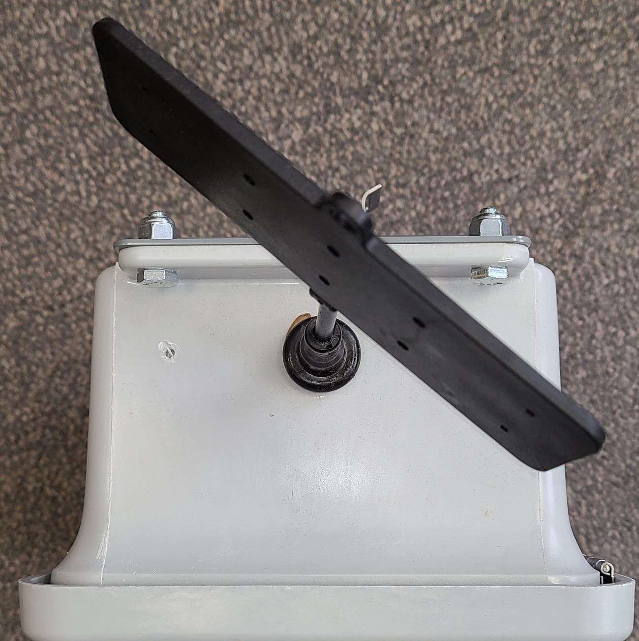
RXNGW1BH1025
May 31, 2021The Gateway is a device to bridge the gap of meters in the field and our server.
Equipment Class
DTS - Digital Transmission System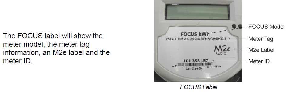
RXN1M2ESS
Nov 11, 2012Models AL & AX Landis & Gyr FOCUS Electric Meters with M2e Radio
Equipment Class
DTS - Digital Transmission System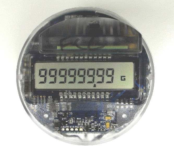
RXN10RR1
Dec 26, 2010Electronic register with embedded M2 radio
Equipment Class
DTS - Digital Transmission System
RXN1207R2SSL
Jan 22, 2008R2 Utility Radio Transceiver
Equipment Class
DTS - Digital Transmission System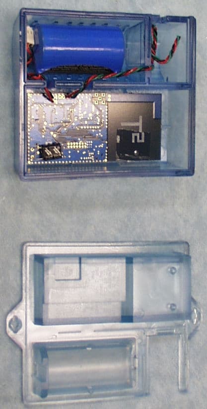
RXN610M2SSL
Sep 17, 2007M2 Utility Radio Transceiver
Equipment Class
DXT - Part 15 Low Power Transceiver, Rx Verified