RXUSM-2102EMobile radio for vehicle
Maxon CIC Corp.
Click to zoom
Application Details
- Equipment Class
- TNB - Licensed Non-Broadcast Station Transmitter
- Date of Grant
- Dec 26, 2013
- Application Purpose
- Original Equipment
- Date of Application
- Dec 26, 2013
- Equipment Note
- Mobile radio for vehicle
- Frequency Range
- 136.00000000 - 174.00000000
- Company
- Maxon CIC Corp.
- Country
- South Korea
Documents & Files
Document Text
Text extracted from the exhibit documents filed with the FCC. Open a document above to read the original.
Users Manual
PM180V / SM-2 102E SERIES MOBILE 1 PM180 V / SM-2102E MOBILE TRANSCEIVER OPERATIONAL DESCRIPTTION PM180V / SM-2 102E SERIES MOBILE 2 WARNINGS > WARNING! NEVER connect the transceiver to an AC outlet. This may pose a fire hazard or result in an electric shock. > NEVER operate the radio transmitter suitable Artificial load connected. > NEVER connect the transceiver to a power source of more than 16V DC such as a 24V battery. This connection will ruin the transceiver. > NEVER cut the DC power cable between the DC Plug and fuse holder. If an incorrect connection Is made after cutting, the transceiver might be damaged. Must connect fuse (32V T10AL) before installation. Replace only with same or equivalent type of use. > NEVER place the transceiver where normal operation of the vehicle may be hindered or where it could cause bodily injury. > NEVER allow children to touch the transceiver. > NEVER expose the transceiver to rain, snow or any liquids. > NEVER modify a radio or accessory except as instructed in the service manual, engineering bulletins or formal communication as this may invalidate any warranty, guarantee or type approval. > USE the supplied microphone only. Other Microphones have different pin assignments and may damage the transceiver. (ACC-700 ) > DO NOT use or place the transceiver in areas with temperatures below -30°C or above +60°C, In areas subject to direct sunlight, such as the dashboard. > AVOID operating the transceiver without running The vehicle’s engine. The vehicle’s battery will quickly run out if the transceiver transmits while the vehicle’s engine OFF > AVOID placing the transceiver in excessively dusty environments. > AVOID placing the transceiver against walls. This will obstruct heat dissipation. > AVOID the use of chemical agents such as benzin or alcohol when cleaning, as they damage the transceiver surfaces. > BE CAREFUL ! The transceiver will become hot when operating continuously for long periods. > DO NOT operate this equipment in environments containing explosive materials or vapour. One or more of the following statements may be applicable: FCC WARNING This equipment generates or users radio frequency energy. Changes or modifications to this equipment may cause harmful interference unless the modifications are expressly approved in the instruction manual. The user could lose the authority to operate this equipment if an unauthorized change or modification is mode. INFORMATION TO THE DIGITAL DEVICE USER REQUIRED BY THE FCC This equipment has been tested and found to comply with the limits for a class B digital device, pursuant to part 15 of the FCC rules. These limits are designed to provide reasonable protection against harmful interference in a residential installation. PM180V / SM-2 102E SERIES MOBILE 3 This equipment generates, uses and can generate radio frequency energy and, if not installed and used in accordance with the instructions, may cause harmful interference to radio communications. However, there is no guarantee that the interference will not occur in a particular installation. If this equipment does cause harmful interference to radio or television reception, which can be determined to try to correct the interference by one or more of the following measures: > Reorient or relocate the receiving antenna. > Increase the separation between the equipment and receiver. > Connect the equipment to an outlet on a circuit different form that to which the receiver is connected. > Consult the dealer for technical assistance. MANDATORY SAFETY INSTRUCTIONS TO INSTALLERS AND USERS > Use only manufacturer or dealer supplied antennas. > Antenna minimum safe distance : 150 cm . > Antenna gain : 0 dBd referenced to a dipole. The federal communications commission has adopted a safety standard for human exposure to RF energy which is below the OSHA limits. > Antenna mounting : The antenna supplied by the manufacturer or radio dealer must not be mounted at a location such that during radio trans mission, any person or persons can come closer than the above indicated minimum safe distance to the antenna, i.e.150 cm. > T o comply with current FCC RX exposure limits, the antenna must be installed at or exceeding the minimum safe distance shown above, and in accordance with the requirements of the antenna manufacturer or supplier. > Vehicle installation : the antenna can be mounted at the center of a vehicle metal roof or trunk lid, if the minimum safe distance is observed. > Base station installation: The antenna should be fixed-mounted on an outdoor permanent structure. RF exposure compliance must be addressed at the time of installation. Antenna substitution: Do not substitute any antenna for the one supplied or recommended by the manufacturer or radio dealer or the manufacturer for further instructions. You,as the qualified end-user of this radio device must control the exposure conditions of bystanders to ensure the minimum separation distance is maintained between the antenna and nearby persons for satisfying RF exposure compliance. The operation of this transmitter must satisfy the requirements of occupational/ controlled exposure environment, for work-related use, transmit only when person are at least the minimum distance from the properly installed, externally mounted antenna. Tr ansmit only when people outside the vehicle are at least the recommended minimum lateral distance away from the antenna/vehicle. PM180V / SM-2 102E SERIES MOBILE 4 TABLE OF CONTENTS 1. SPECIFICATIONS . 2. DESCRIPTION OF UNIT . 3. THEORY OF OPERATION . 4. A LIGNMENT PROCEDURE . 5. EXPLODED VIEW . 6. PARTS LIST . 7. PCB LAYOUT AND CIRCUIT DIAGRAMS . 8. BLOCK DIAGRAM . PM180V / SM-2 102E SERIES MOBILE 5 INTRODUCTION The PM-180V,SM2102E of mobile radios from Maxon, utilizes the latest technology in its design and manufacturing. Both the VHF and UHF models are PLL (Phase Lock Loop Synthesizer) / microprocessor controlled, and offer 5 or 25 watts of power with 99 channel capability…
Text truncated - open the document above for the full version.
Cover Letter(s)
Date: May 27, 2013 Federal Communications Commission 7435 Oakland Mills Road Columbia MD 21046 c.c. Compliance Certification Services Certification Division 47173 Benicia Street Fremont, CA 94538, USA To whom it may concern: I, the undersigned, hereby authorize Mr. CY_Choi/ RAPA, to act on our behalf in all manners relating to application for equipment authorization, including signing of all documents relating to these matters. Any and all acts carried out by Mr. CY_Choi / RAPA on our behalf shall have the same effect as acts of our own. I, the undersigned, hereby certify that we are not subject to a denial of federal benefits, that includes FCC benefits, pursuant to Section 5301 of the Anti-Drug Abuse Act of 1988, 21 U.S.C. 853(a). In authorizing UL Korea as our agent, we still recognize that we are responsible to: a) comply with the relevant provisions of the certification program; b) make all necessary arrangements for the conduct of the evaluation, including provision for examining documentation and access to all areas, records (including internal audit reports) and personnel for the purposes of evaluation (e.g. testing, inspection, assessment, surveillance, reassessment) and resolution of complaints; c) make claims regarding certification only in respect of the scope for which certification has been granted; d) do not use our product certification in such a manner as to bring the Certification Division into disrepute and not make any statement regarding our product certification which the Certification Division may consider misleading or unauthorized; e) upon suspension or cancellation of certification, discontinue use of all advertising matter that contains any reference thereto and return any certification documents as required by the Certification Division; f) use certification only to indicate the products are certified as being in conformity with specified standards; g) endeavor to ensure that no certificate or report nor any part thereof is used in a misleading manner; h) ensure that any reference to our product certification in communication media such as documents, brochures or advertising, complies with the requirements of the Certification Division; i) keep a record of all complaints made known to the us relating to the product’s compliance with requirements of the relevant standard and to make these records available to the Certification Division when requested; j) take appropriate action with respect to such complaints and any deficiencies found in products or services that affect compliance with the requirements for certification; k) document the actions taken. This authorization is valid until further written notice from the applicant. Sincerely Yours, Name: Hyun-Koo Kang Title: Manager REMARK: 1. This authorization letter will be sent along with your application when filing with the Certification Division. 2. Please follow the format and type it on company letterhead and send original to us. 3. Authorized signature must be in agreement with grantee code contact in FCC database.
Cover Letter(s)
Maxon CIC Corp. RM 612, Starwood Plaza, 5439-1, Chongho Building, #7-61 Yangjea-Dong, Seocho-Gu, Seoul, 137-130, Korea TEL No : +82-2-3498-3060 FAX No : +82-2-3498-3115 Federal Communications Commission 7435 Oakland Mills Road Columbia MD 21046 Subject: Request for Confidentiality FCC ID: RXUSM-2102E To Whom It May Concern: Pursuant to the provisions of Sections 0.457 and 0.459 of the Commission’s rules (47 CFR §§ 0.457, 0.459), we are requesting the Commission to withhold the following attachments as confidential document from public disclosure indefinitely. 1. Block Diagram 2. Schematic Diagram 3. Operational Description 4. Part List A bove mentioned document contains detailed system and equipment description are considered as proprietary information in operation of the equipment. The public disclosure of above documents might be harmful to our company and would give competitor an unfair advantage in the market. It is our understanding that all measurement test reports, FCC ID label format and correspondent during certification review process cannot be granted as confidential documents and those information will be available for public review once the grant of equipment authorization is issued. Sincerely Yours, Hyun-Koo Kang (Manager) Maxon CIC Corp.
Cover Letter(s)
Justification Letter DATE: January 5, 2014 Federal Communications Commission Authorization & Evaluation Division 7435 Oakland Mills Road Colombia, Maryland 21046 FCC ID: RXUSM-2102E Model: SM-2102E Dear Sir/Madam, We, Maxon CIC Corp. acknowledge that this device will not be marketed to USA users with the frequency band which is not allowed by rule part 90.and it is a violation of FCC rules if this device is operated on unauthorised frequencies inside the U.S.A. We, Maxon CIC Corp. acknowledge this equipment meets the requirements of FCC Rules, Parts 90.203 (e) and (g) as applicable. Programming of this product's transmit frequencies can be performed ONLY by the manufacturer or by service or maintenance personnel. The operator cannot program transmit frequencies using the equipment's external operation. Sincerely yours, Maxon CIC Corp. Hyun-Koo Kang / Senior Manager Fax: +82-2-3498-3113 Tel: +82-2-3498-3045 E-mail: [email protected]
External Photos
Maxon CIC Corp. Mobile radio for vehicle SM-2102E It should not be reproduced in full or partly without the written approval by TCL of RAPA. Testing and Certification Laboratory 3. External Photos 1. Full Maxon CIC Corp. Mobile radio for vehicle SM-2102E It should not be reproduced in full or partly without the written approval by TCL of RAPA. Testing and Certification Laboratory 2. Front 3. Real Maxon CIC Corp. Mobile radio for vehicle SM-2102E It should not be reproduced in full or partly without the written approval by TCL of RAPA. Testing and Certification Laboratory 4. Top 5. Bottom Maxon CIC Corp. Mobile radio for vehicle SM-2102E It should not be reproduced in full or partly without the written approval by TCL of RAPA. Testing and Certification Laboratory 6. Left 7. Right
ID Label/Location Info
Maxon CIC Corp. Mobile radio for vehicle SM-2102E It should not be reproduced in full or partly without the written approval by TCL of RAPA. Testing and Certification Laboratory Appendix 2. FCC ID Label and Location
Internal Photos
Maxon CIC Corp. Mobile radio for vehicle SM-2102E It should not be reproduced in full or partly without the written approval by TCL of RAPA. Testing and Certification Laboratory 3 Internal Photos of EUT 1. Inside Maxon CIC Corp. Mobile radio for vehicle SM-2102E It should not be reproduced in full or partly without the written approval by TCL of RAPA. Testing and Certification Laboratory 2. Front Maxon CIC Corp. Mobile radio for vehicle SM-2102E It should not be reproduced in full or partly without the written approval by TCL of RAPA. Testing and Certification Laboratory 3. Back
RF Exposure Info
Page : 54 of 55 Report No. : RAPA13-O-335 It should not be reproduced in full or partly without the written approval by TCL of RAPA. FCC CFR Part 90(Rev.0) Testing and Certification Laboratory 4. RF exposure statement According to §1.1307, systems operating under the provisions of this section shall be operated in a manner that ensures that the public is not exposed to radio frequency energy level in excess of the Commission’s guidelines. According to §1.1310 and §2.1091 RF exposure is calculated. Limits for General Population/Uncontrolled Exposure Frequency Range [MHz] Electric Field Strength [V/m] Magnetic Field Strength [A/m] Power Density [mW/cm 2 ] Averaging Time [minute] Limits for General Population/Uncontrolled Exposure 0.3 – 1.34 614 1.63 100 30 1.34 – 30 824/f 2.19/f 180/f 2 30 30 – 300 27.5 0.073 0.2 30 300 – 1500 - - f/1500 30 1500 – 100 000 - - 1.0 30 ※ f = frequency in MHz 4.1 Friis transmission formula 2 4R GP P out d P d = Power density P out = power input to antenna G = power gain R = distance to the center of radiation of the antenna d out P GP R 4 4.2 Calculation of MPE Frequency [MHz] Output power [dBm] Antenna gain [dBi] Average power Power density Minimum safety distance [cm] [dBm] [W] [mW/cm 2 ][W/m 2 ] 135.0 43.72 2.14 45.86 38.55 0.136 1.364 123.88 155.0 43.75 2.14 45.89 38.82 0.137 1.374 124.31 174.0 43.86 2.14 46.00 39.81 0.141 1.409 125.89 ※ Calculated minimum separation distance from antenna : 150 cm
Test Report
Page : 1 of 55 Report No. : RAPA13-O-335 It should not be reproduced in full or partly without the written approval by TCL of RAPA. FCC CFR Part 90(Rev.0) Testing and Certification Laboratory TEST REPORT Report Number RAPA13-O-335 Type of Equipment Mobile radio for vehicle (Two way radio land mobile service) Model Name SM-2102E FCC ID RXUSM-2102E IC Number 153B-SM2102E Applicant Name Maxon CIC Corp. Logo Address Chongho Building, #7-61 Yangjae-Dong, Seocho-Gu, Seoul, 137-130, Korea Manufacturer Name Maxon CIC Thailand Co., Ltd(MCTL) Address 40/23 Moo 5 Rojana Industrial Park Tambol U-Thai, Amphur U-Thai Ayutthaya 13210 Thailand Test duration May 14, 2013 to May 30, 2013 Date of issue June 04, 2013 Total Page 55 pages (including this page) SUMMARY The equipment complies with FCC CFR 47 Part 90 and IC RSS-119. This test report contains only the results of a single test of the sample supplied for the examination. It is not a general valid assessment of the features of the respective products of the mass-production. Date : June 04, 2013 Date : June 04, 2013 Prepared and tested by Tae Yang, Yoon Reviewed by SuKil, Park Manager /TCA of RAPA Executive Managing Director/TCA of RAPA Page : 2 of 55 Report No. : RAPA13-O-335 It should not be reproduced in full or partly without the written approval by TCL of RAPA. FCC CFR Part 90(Rev.0) Testing and Certification Laboratory CONTENTS 1. General description of EUT ............................................................................................................. 3 1.1 Applicant .................................................................................................................................................... 3 1.2 Manufacturer ............................................................................................................................................. 3 1.3 Basic description of EUT.......................................................................................................................... 3 1.4 Electrical specification ............................................................................................................................. 4 1.5 EUT operating conditions & test configuration ..................................................................................... 4 1.6 DC Voltage and Currents .......................................................................................................................... 5 2. General information of test ............................................................................................................. 6 2.1 Standard for measurement methods ...................................................................................................... 6 2.2 Description of EUT modification ............................................................................................................. 6 2.3 Description of test system configuration ............................................................................................... 6 3. Measurement data ............................................................................................................................ 7 3.1 Radiated emission .................................................................................................................................... 7 3.2 RF power output (conducted) .................................................................................................................. 9 3.3 Occupied bandwidth ............................................................................................................................... 17 3.4 Audio frequency response ..................................................................................................................... 32 3.5 Audio low pass filter response .............................................................................................................. 35 3.6 Modulation limiting ................................................................................................................................. 37 3.7 Spurious emissions at antenna terminals ............................................................................................ 41 3.8 Field strength of spurious radiation ..................................................................................................... 43 4. RF exposure statement ................................................................................................................. 54 4.1 Friis transmission formula ..................................................................................................................... 54 4.2 Calculation of MPE .................................................................................................................................. 54 5. Test equipment list ........................................................................................................................ 55 Page : 3 of 55 Report No. : RAPA13-O-335 It should not be reproduced in full or partly without the written approval by TCL of RAPA. FCC CFR Part 90(Rev.0) Testing and Certification Laboratory 1. General description of EUT 1.1 Applicant • Company name : Maxon CIC Corp. • Address : Chongho Building, #7-61 Yangjae-Dong, Seocho-Gu, Seoul, 137- 130, Korea • Contact person : Choong Kyun Kim • Phone/Fax : 82-2-3498-3041 / 82-2-3498-3113 1.2 Manufacturer • Company name : Maxon CIC Thailand Co., Ltd(MCTL) • Address : 40/23 Moo 5 Rojana Industrial Park Tambol U-Thai, Amphur U-Thai Ayutthaya 13210 Thailand • Phone / Fax : 66-35-719-498 / 66-35-719-492 1.3 Basic description of EUT • Product name : Mobile radio for vehicle (Two way radio land mobile service) • Model name : SM-2102E • Frequency : 136 MHz – 174 MHz • Output power : 25 W / 5 W • Modulation method: FM (11k0F3E) • FCC Rule Part(s) : FCC Part 90 / Private land mobile radio services • IC Rule Part(s) : IC RSS-119 / Land mobile and fixed radio transmitt…
Text truncated - open the document above for the full version.
Test Setup Photos
Maxon CIC Corp. Mobile radio for vehicle SM-2102E It should not be reproduced in full or partly without the written approval by TCL of RAPA. Testing and Certification Laboratory 1. Photos of Test Setup 1. Test Setup of Radiation
Contact Information
Applicant
Hyun-Koo Kang(Manager)
Test Firm
Testing and Certification Agency of RAPAWoong-gul Kang
Technical Specifications
| # | Rule Parts | Frequency Range | Power Output | Emission | Tolerance |
|---|---|---|---|---|---|
| 2 | 9 | 136 MHz - 174 MHz | 4.79 W | 11K0F3E | 2.5 ppm |
Other Applications from Maxon CIC Corp.
RXUSP7402
Jan 16, 2008UHF LMR
Equipment Class
TNF - Licensed Non-Broadcast Transmitter Held to Face
RXUSL7402
Jan 13, 2008UHF LMR
Equipment Class
TNF - Licensed Non-Broadcast Transmitter Held to Face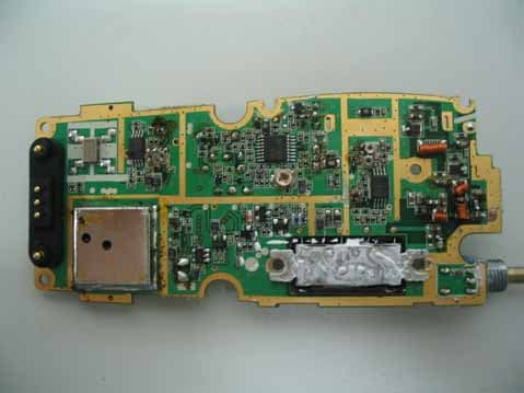
RXUSP6102
Nov 12, 2007Private Land Mobile Radio for Handheld (VHF)
Equipment Class
TNF - Licensed Non-Broadcast Transmitter Held to Face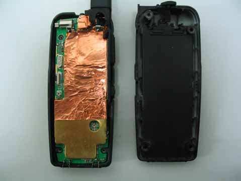
RXUSG9000
Oct 01, 2007FRS/GMRS Transceiver
Equipment Class
FRF - Part 95 Family Radio Face Held Transmitter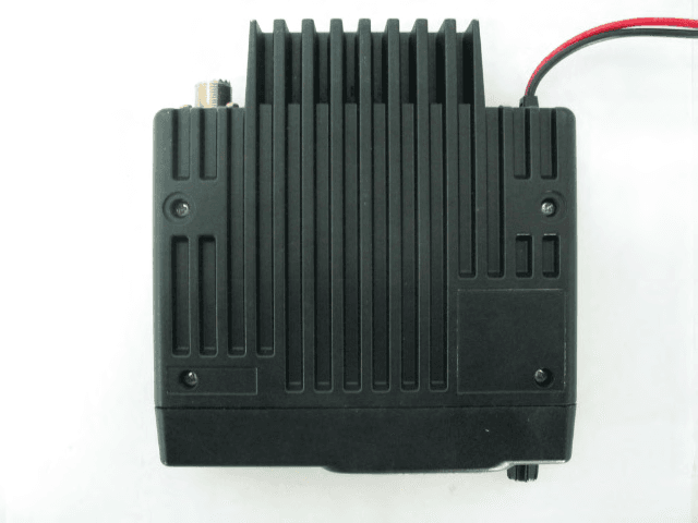
RXUSM2402
Feb 14, 2007Private Land Mobile Radio for Vehicle (UHF)
Equipment Class
TNB - Licensed Non-Broadcast Station Transmitter