RXUSP6102Private Land Mobile Radio for Handheld (VHF)
Maxon CIC Corp.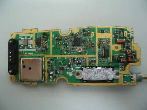
Click to zoom
Application Details
- Equipment Class
- TNF - Licensed Non-Broadcast Transmitter Held to Face
- Date of Grant
- Nov 12, 2007
- Application Purpose
- Original Equipment
- Date of Application
- Nov 12, 2007
- Equipment Note
- Private Land Mobile Radio for Handheld (VHF)
- Frequency Range
- 148.00000000 - 174.00000000
- Company
- Maxon CIC Corp.
- Country
- South Korea
Documents & Files
Document Text
Text extracted from the exhibit documents filed with the FCC. Open a document above to read the original.
Users Manual
1 SP-6102 About Your S P-6102 Radio Maxon's S P-6102 radio feature up to 13 groups and up to 16 channel operation per group for a total channel capacity of 208 channels of superior performance and reliability. Operation and functions for Maxon's S P-6102 radios are described in this manual. We urge you to thoroughly read this manual before operating the radio. Application of some of the functions described in this manual is determined by the system you use. Your Maxon Dealer will program your radio so that you have the greatest number of functions possible relative to your needs. Should you have questions regarding the operation of the radio please consult your Maxon Dealer. SP-6102 Specification MODEL: S P- 6102 MODEL CODE: 7858 EQUIPMENT TYPE: Handportable PERFORMANCE SPECIFICATIONS: TIA/EIA-603/ETSI300.086 BAND: VHF2(148~174Mhz) CHANNEL SPACINGS: 12.5KHz, 25KHz PROGRAMMBLE RF OUTPUT POWER: 5 / 1 WATT MODULATION TYPE: F3E AUDIO POWER: 500mW ( EXT WITH 16 OHM) 1W ( INT WITH 4 OHM) INTERMEDIATE FREQUENCY: 45.1MHz 455KHz CHANNELS: 208 Channel FREQUENCY SOURCE: SYNTHESIZER POWER SUPPLY: Li-ION(1750mA) 7.5 VDC NOMINAL EXTREME +/- 10% VDC EXTREME Safety Information WARNING - DO NOT hold the radio in such a manner that the antenna is next to, or touching, exposed parts of the body, especially the face or eyes, while transmitting. WARNING -DO NOT allow children to operate transmitter - equipped radio equipment. CAUTION -DO NOT operate the radio near unshielded electrical blasting caps or in an explosive atmosphere unless it is a type especially designed and qualified for such use. 2 CAUTION - DO NOT press and hold the transmit switch (P-T-T) when not actually wishing to transmit. NEVER use the radio in an aircraft NEVER use the radio near to sensitive medical equipment or in areas where instructed , e.g. Petrol filling stations When used in a vehicle, do not mount the radio unit on or near the Airbag or Airbag activating device. The use of an accessory not recommended or supplied by Maxon may cause damage to equipment or injury to personnel , and will invalidate warranty. When using any of the charging accessories, the mains socket-outlet must be installed near the equipment . The outlet must not be obstructed and must be easily accessible at all times. Never attempt to disassemble , modify or repair the unit unless the work is carried out by a Maxon approved Reseller. Incorrect assembly, modification or repair may cause irreparable damage to your unit and will invalidate warranty . For service or repair always return your radio to an authorized Maxon Reseller. Unpacking Information Remove and carefully inspect the contents of your package(s) for the following items: Radio Battery Pack Battery Charger Battery Charger Power Supply Antenna Spring Belt Clip Operating Instructions If any items are missing, please contact your Dealer or Maxon. S P-6102 Features · Wideband frequency separation · 1 or 5 W programmable output power · Programmable 12.5/25 kHz channel spacing · Channel scan · Priority channel scan · Look back channel · CTCSS/DCS/DTMF tone signaling · Busy channel lockout · Time-out timer Scan List Edit Priority Channel Edit Description of Radio Components 1) Antenna Receptacle 2) Channel Up/Down Button 3) On/Off - Volume Control 3 4) GWR/PWR Button 5) Lamp / Lock Button 6) Battery Latch 7) Push-To-Talk (PTT) 8) Monitor Button 9) Menu/Scan Button 10) Emergency Button 11) Microphone 12) Accessory Connector 13) Belt Clip 14) Battery 15) Battery Charge Contacts 16) LCD 17) Speaker Antenna Installation Fasten the antenna to the radio by turning the antenna clockwise into the receptacle on top of the radio. Installing and Removing the Battery Pack To Install: Position the guides of the battery in line with the radio battery guide rails and slide the battery into position until a click is heard. To Remove: Holding radio in one hand, push and hold battery latch button located in the bottom of the Set , held as if looking at the back of the unit. Hold radio firmly and slide battery in downward direction while pushing the battery latch button. Attaching and Removing the Belt Clip To Install: Install belt clip onto the belt clip holder located on the upper left hand corner of the radio, held as if looking at the back of the unit. Locate slot location in belt clip and push belt clip until a click is heard. To Remove: Push and hold release button located at top of belt clip and slide clip off the belt clip holder. Battery Charging and Care To ensure peak performance from your radio, the battery pack must be fully charged. Proper care and charging will allow maximum performance and life of your battery pack. SPC-3000 Desktop Charger provides 2 hours charging to one radio and one battery. 4 To receive maximum performance from your radio and battery pack, periodically completely discharge and recharge the battery pack. Status Indicators and Audible Alert Tones Your S P-6102 has a sophisticated microprocessor control which provides a series of audible alert tones. Upon initial power up, a quick melody indicates that the self-test of the microprocessor functions has been completed satisfactorily. A series of tones may be sounded with any of the following conditions: · Attempt to transmit on a channel set for receive only · Attempt to transmit on a channel that is already in use when busy channel lockout has been programmed into the radio * · Transmitting time has exceeded time-out timer programmed length * · Low battery condition · Selecting a channel with no programmed frequency * Indicates a function that is initially programmed into the radio by your Maxon Dealer. NOTE: All audible tones can be programmed off for silent operation. Status Decription LED colorLCD Indication Audible Tone Normal Power On - Ready N/A Channel number Melody Call Received Orange Channel number N/A Correct Call Green Channel number N/A Busy Channel Orange Channel number N/A Transmit Red Channel number N/A Transmit not allowed …
Text truncated - open the document above for the full version.
Cover Letter(s)
MAXON CIC Corp. Chongho Bldg, #7-61, Yangjae-dong, Seocho-gu, Seoul, 137-130 Korea TEL : +82-2-3498-3114 / FAX : +82-2-3498-3115 Federal Communications Commission 7435 Oakland Mills Road Columbia, MD 21046 Gentlemen: This letter is to comply with Section 0.457(d)(2)(i) and 0.459 pertaining to confidential material. We, MAXON CIC Corp., would like the following documents regarding this submission for FCC ID: RXUSP6102 to be kept confidential. 1. Block Diagram 2. Schematics 3. Parts List 4. Theory of operation The above material contains trade secrets or technical data, which would customarily be guarded from competitors. We do not want these documents to be accessible to the general public. Sincerely, Hyun-Gu Kang / Manager MAXON CIC Corp.
Cover Letter(s)
MAXON CIC Corp. Chongho Bldg, #7-61, Yangjae-dong, Seocho-gu, Seoul, 137-130 Korea TEL : +82-2-3498-3114 / FAX : +82-2-3498-3115 Federal Communications Commission October 5, 2007 Authorization & Evaluation Division 7435 Oakland Mills Road Columbia, Maryland, MD 21046, USA Re. FCC ID : RXUSP6102 Subject : Justification Letter for extended frequency range use Gentlemen, We, Maxon, advices that SP6102 Private Handheld Land Mobile Radio Transceiver has the design capability to be programmed and operated only for the frequency band 148-174 MHz. We, Maxon, also acknowledge that it is a violation of FCC rules for this device to be operated on unauthorized frequencies inside the USA. We, Maxon, acknowledge that this device will not be marketed to USA users with the frequency band which is not allowed by rule part as well. Pls note that Licensed End users shall not have any access to external controls that willallow them to programme the equipment. Equipment programming is the responsibility of Maxon approved service agents Sincerely, Hyun-Gu Kang / Manager /MAXON CIC Corp.
External Photos
FCC ID : RXUSP6102 Report File No. : STROR-07-092 Page : 47 of 52 The results shown in this test report refer only to the sample(s) tested unless otherwise stated. This test report cannot be reproduced, except in full, without prior written permission of the Company. Tel. +82 31 428 5700 / Fax. +82 31 427 2371 www.electrolab.kr.sgs.com Appendix B Photos of the EUT ● Front View of EUT ● Rear View of EUT FCC ID : RXUSP6102 Report File No. : STROR-07-092 Page : 48 of 52 The results shown in this test report refer only to the sample(s) tested unless otherwise stated. This test report cannot be reproduced, except in full, without prior written permission of the Company. Tel. +82 31 428 5700 / Fax. +82 31 427 2371 www.electrolab.kr.sgs.com ● Left View of EUT ● Right View of EUT FCC ID : RXUSP6102 Report File No. : STROR-07-092 Page : 49 of 52 The results shown in this test report refer only to the sample(s) tested unless otherwise stated. This test report cannot be reproduced, except in full, without prior written permission of the Company. Tel. +82 31 428 5700 / Fax. +82 31 427 2371 www.electrolab.kr.sgs.com ● Top View of EUT ● Bottom View of EUT
ID Label/Location Info
FCC ID LABEL 1. FCC ID label drawing 2. FCC ID label location MAXON CIC Corp. Model : SP6102 FCC ID : RXUSP6102 Made in Korea
Internal Photos
FCC ID : RXUSP6102 Report File No. : STROR-07-092 Page : 50 of 52 The results shown in this test report refer only to the sample(s) tested unless otherwise stated. This test report cannot be reproduced, except in full, without prior written permission of the Company. Tel. +82 31 428 5700 / Fax. +82 31 427 2371 www.electrolab.kr.sgs.com ● Inner View of EUT ● Top of Main-board(Can’t remove shield cap) FCC ID : RXUSP6102 Report File No. : STROR-07-092 Page : 51 of 52 The results shown in this test report refer only to the sample(s) tested unless otherwise stated. This test report cannot be reproduced, except in full, without prior written permission of the Company. Tel. +82 31 428 5700 / Fax. +82 31 427 2371 www.electrolab.kr.sgs.com ● Bottom of Main-board ● Top of Keyboard(Can’t remove shield cap) FCC ID : RXUSP6102 Report File No. : STROR-07-092 Page : 52 of 52 The results shown in this test report refer only to the sample(s) tested unless otherwise stated. This test report cannot be reproduced, except in full, without prior written permission of the Company. Tel. +82 31 428 5700 / Fax. +82 31 427 2371 www.electrolab.kr.sgs.com ● Bottom of Keyboard
Test Report
FCC ID : RXUSP6102 Report File No. : STROR-07-092 Page : 1 of 52 The results shown in this test report refer only to the sample(s) tested unless otherwise stated. This test report cannot be reproduced, except in full, without prior written permission of the Company. Tel. +82 31 428 5700 / Fax. +82 31 427 2371 www.electrolab.kr.sgs.com TEST REPORT OF FCC Part 90, Part 2 FCC ID : RXUSP6102 Equipment Under Test : Private Land Mobile Radio for Handheld(VHF) Model No. : SP6102 Serial No. : N/A Applicant : MAXON CIC Corp. Manufacturer : MAXON CIC Corp. Date of Test(s) : 2007-10-02 ~ 2007-10-19 Date of Issue : 2007-10-26 In the configuration tested, the EUT complied with the standards specified above. Te s t e d B y : Date 2007-10-26 Feel Jeong Approved By Date 2007-10-26 Denny Ham FCC ID : RXUSP6102 Report File No. : STROR-07-092 Page : 2 of 52 The results shown in this test report refer only to the sample(s) tested unless otherwise stated. This test report cannot be reproduced, except in full, without prior written permission of the Company. Tel. +82 31 428 5700 / Fax. +82 31 427 2371 www.electrolab.kr.sgs.com INDEX TABLE OF CONTENTS Page 1. General Information ------------------------------------------------------------------------------ 3 2. Output Power Conducted-------------------------------------------------------------------------6 3. Radiated Spurious Emissions-------------------------------------------------------------------- 8 4. Conducted Spurious Emissions------------------------------------------------------------------15 5. Audio Frequency Response-----------------------------------------------------------------------28 6. Audio Low Pass Filter Frequency Response-------------------------------------------------- 30 7. Modulation Limiting-------------------------------------------------------------------------------32 8. Occupied Bandwidth-------------------------------------------------------------------------------34 9. Frequency Stability---------------------------------------------------------------------------------37 10. Transient Frequency Behaviours of the Transmitter --------------------------------------39 Appendix A. Photo of Radiated Spurious Emissions Test Appendix B. Photos of the EUT FCC ID : RXUSP6102 Report File No. : STROR-07-092 Page : 3 of 52 The results shown in this test report refer only to the sample(s) tested unless otherwise stated. This test report cannot be reproduced, except in full, without prior written permission of the Company. Tel. +82 31 428 5700 / Fax. +82 31 427 2371 www.electrolab.kr.sgs.com 1. General Information 1-1. Testing Laboratory SGS Testing Korea Co., Ltd. Wireless Div. 2FL, 18-34, Sanbon-dong, Gunpo-si, Gyeonggi-do, Korea 435-040 www.electrolab.kr.sgs.com Telephone : +82 +31 428 5700 FAX : +82 +31 427 2371 1-2. Details of Applicant Applicant : MAXON CIC Corp. Address : Chongho Bldg, #7-61, Yangjae-dong, Seocho-gu, Seoul, Korea Contact Person : Phillip Son Phone No. : 82-2-3498-3054 Fax No. : 82-2-3498-3115 1-3 Description of EUT Kind of Product Private Land Mobile Radio for Handheld(VHF) Model Name SP6102 Serial Number N/A Power Supply DC 7.5 V Frequency Range 148 MHz ~ 174 MHz Transmit Power 1W(Low), 5 W(High) Modulation Technique FM Number of Channels 208 Channels Operating Conditions -30 ~ 60 deg C Antenna Type Connected Type 1-4 Details of modification FCC ID : RXUSP6102 Report File No. : STROR-07-092 Page : 4 of 52 The results shown in this test report refer only to the sample(s) tested unless otherwise stated. This test report cannot be reproduced, except in full, without prior written permission of the Company. Tel. +82 31 428 5700 / Fax. +82 31 427 2371 www.electrolab.kr.sgs.com 1-5. Test Equipment List EQUIPMENT MANUFACTURER MODEL CAL DUE. Signal Generator Agilent E4438C May 2008 Spectrum Analyzer Agilent E4440A May 2008 Spectrum Analyzer R&S FSP40 Jan. 2008 Audio Analyzer H.P. 8903B Dec.2007 Modulation Analyzer H.P. 8901B Dec.2007 DC Power Supply Agilent 6674A May 2008 Tem/Hum Chamber Han-Gil HGTP-4050 Oct.2008 Power Sensor Agilent E9327A May 2008 Power Meter Agilent 4416A May 2008 Attenuator Weincshel AZ3096 Dec.2007 Preamplifier Agilent 8449B May 2008 Preamplifier Agilent 8447F Jun.2008 Log-periodic Rohde & Schwarz UHALP9107 Jan.2009 Biconical Antenna Schwarzbeck VHA9103 Mar.2008 Horn Antenna Rohde & Schwarz HF906 Mar.2008 Signal Generator R&S SMR 20 Dec.2007 Horn Antenna R&S HF906 Aug.2008 Biconcai Antenna R&S HK116 May 2009 Log-Periodic Antenna R&S HL223 May 2009 Turn Table INN-CO CT 0800 N.C.R Antenna Mast INN-CO MA 2000 N.C.R Controller INN-CO CO 2000 N.C.R Anechoic Chamber SY Corporation 10m 5m 5m Feb. 2008 FCC ID : RXUSP6102 Report File No. : STROR-07-092 Page : 5 of 52 The results shown in this test report refer only to the sample(s) tested unless otherwise stated. This test report cannot be reproduced, except in full, without prior written permission of the Company. Tel. +82 31 428 5700 / Fax. +82 31 427 2371 www.electrolab.kr.sgs.com 1.6 Summary of Test Results Description of Test FCC Rule Result Output Power Conducted 2.1046(a), 90.205 Complied Radiated Spurious Emissions 2.1053(a), 90.210 Complied Conducted Spurious Emissions 2.1051, 90.210 Complied Audio Frequency Response 2.1047(a) Complied Audio Low Pass Filter Frequency Response 2.1047(a) Complied Modulation Limiting 2.1047(b) Complied Occupied Bandwidth 2.1049, 90.210 Complied Frequency Stability 90.213, 2.1055 Complied Transient Frequency Behaviour of the Transmitter 90.214 Complied FCC ID : RXUSP6102 Report File No. : STROR-07-092 Page : 6 of 52 The results shown in this test report refer only to the sample(s) tested unless otherwise stated. This test report cannot be reproduced, except in full, without prior written permission of the Company. Tel. +82 31 428 5700 / Fax. +82 31 427 2371 www.electrolab.kr.sgs.com 2. Output Power Conducted : FCC 2.1046(a), FCC90.205 2.1. Limit According to §90.205(r), The output power shall not exceed by more than 20 per…
Text truncated - open the document above for the full version.
Test Report
FCC ID : RXUSP6102 Report File No. : STROR-07-092 Page : 32 of 52 The results shown in this test report refer only to the sample(s) tested unless otherwise stated. This test report cannot be reproduced, except in full, without prior written permission of the Company. Tel. +82 31 428 5700 / Fax. +82 31 427 2371 www.electrolab.kr.sgs.com 7. Modulation Limiting: FCC 2.1047(b) 7.1. Limit Minimum Standard - The transmitter modulation must not exceed rated system deviation at any frequency input or reasonable change in input level. 7.2. Test Procedure 1. Modulation limiting is the transmitter circuit’s ability to limit the transmitter from producing deviations in excess of rated system deviation. 2. The modulation response is measured at certain modulation frequencies, related to 1000Hz reference signal. 3. The basic setting is 60% of full rated deviation which will be increased the audio generator level from –20 dB to 20 dB in nine steps. 4. Tests are performed for positive and negative modulation. EUT Standard Transmitter Load Audio Generator Test Receiver FCC ID : RXUSP6102 Report File No. : STROR-07-092 Page : 33 of 52 The results shown in this test report refer only to the sample(s) tested unless otherwise stated. This test report cannot be reproduced, except in full, without prior written permission of the Company. Tel. +82 31 428 5700 / Fax. +82 31 427 2371 www.electrolab.kr.sgs.com 7.3. Test Results Ambient temperature : 25 Relative humidity:51% Operating Frequency : 160.0250 MHz Channel : Middle Nominal DC Voltage: 7.5 Vdc 12.5 kHz channel spacing Positive peak deviation [kHz] Negative peak deviation [kHz] Audio input level Relative [dB] 300 Hz 1000 Hz 3000 Hz 300 Hz 1000 Hz 3000 Hz -20 0.049 0.154 0.343 0.054 0.163 0.349 -15 0.072 0.270 0.591 0.072 0.274 0.602 -10 0.116 0.470 1.048 0.113 0.475 1.665 -5 0.193 0.834 1.765 0.189 0.875 1.785 0 0.323 1.500 1.934 0.329 1.500 1.953 5 2.248 2.257 1.956 0.561 2.224 1.970 10 2.122 2.134 1.963 1.353 2.098 1.974 15 2.119 2.120 1.960 1.986 2.099 1.982 20 2.106 2.113 1.962 2.001 2.108 1.978 25 kHz channel spacing Positive peak deviation [kHz] Negative peak deviation [kHz] Audio input level Relative [dB] 300 Hz 1000 Hz 3000 Hz 300 Hz 1000 Hz 3000 Hz -20 0.083 0.291 0.647 0.085 0.304 0.645 -15 0.131 0.516 1.131 0.137 0.529 1.143 -10 0.219 0.900 2.013 0.227 0.934 2.021 -5 0.376 1.623 3.428 0.382 1.653 3.376 0 0.669 3.000 3.759 0.667 3.000 3.671 5 1.178 4.760 3.796 1.170 4.261 3.712 10 3.480 4.481 3.806 2.901 4.020 3.717 15 4.370 4.440 3.802 4.012 4.024 3.722 20 4.172 4.420 3.801 4.014 4.030 3.730 FCC ID : RXUSP6102 Report File No. : STROR-07-092 Page : 34 of 52 The results shown in this test report refer only to the sample(s) tested unless otherwise stated. This test report cannot be reproduced, except in full, without prior written permission of the Company. Tel. +82 31 428 5700 / Fax. +82 31 427 2371 www.electrolab.kr.sgs.com 8. Occupied Bandwidth : FCC 2.1049, FCC 90.210 8.1. Limit According to §90.210, Emission Mask B – 25 kHz channel bandwidth. For Transmitters that are equipped with an audio low-pass filter. Measured Data:(1) On any frequency removed from the assigned frequency by more than 50 percent, but not more than100 percent of the authorized bandwidth : At least 25 dB.(2) On any frequency removed from the assigned frequency by more than 100 percent, but not more than 250 percent of the authorized bandwidth : At least 35 dB.(3) On any frequency removed from the assigned frequency by more than 250 percent of the authorized bandwidth : At least 43+10 log10(P) dB. Emission Mask D - 12.5 kHz channel bandwidth. For Transmitters that designed to operate with 12.5kHz channel bandwidth, any emission must be attenuated below the power (P) of the highest emission contained within the authorized bandwidth as follows: Measured Data:(1) On any frequency from the center of the authorized bandwidth fo to 5.625kHz removed from fo : Zero dB.(2)On any frequency removed from the center of the authorized bandwidth by a displacement frequency (fd in kHz) of more than 5.625 kHz but no more than 12.5kHz. At least 7.27 (fd - 2.88kHz) dB.(3)On any frequency removed from the center of the authorized bandwidth by a displacement frequency (fd in kHz) of more than 12.5kHz: At least 50+10 log10(P) dB or 70 dB, whichever is the lesser attenuation. 8.2. Test Procedure 1. The occupied bandwidth, that is the frequency bandwidth such that, below its lower and above its upper frequency limits, the mean powers radiated are each equal to 0.5 percent of the total mean power radiated by a given emission. 2. The transmitter is modulated by a 2500 Hz tone at an input level 16 dB greater than that necessary to produce 50 percent modulation. 3. The input level shall be established at the frequency of maximum response of the audio modulating circuit. FCC ID : RXUSP6102 Report File No. : STROR-07-092 Page : 35 of 52 The results shown in this test report refer only to the sample(s) tested unless otherwise stated. This test report cannot be reproduced, except in full, without prior written permission of the Company. Tel. +82 31 428 5700 / Fax. +82 31 427 2371 www.electrolab.kr.sgs.com 8.3. Test Results Ambient temperature : 25 Relative humidity:49% Operating Frequency : 160.250 MHz Channel : Middle Nominal DC Voltage: 7.5 Vdc MASK B CHANNEL SPACING = 25 kHz Limits: Are determined by used emission mask. FCC ID : RXUSP6102 Report File No. : STROR-07-092 Page : 36 of 52 The results shown in this test report refer only to the sample(s) tested unless otherwise stated. This test report cannot be reproduced, except in full, without prior written permission of the Company. Tel. +82 31 428 5700 / Fax. +82 31 427 2371 www.electrolab.kr.sgs.com Operating Frequency : 160.0250 MHz Channel : Middle Nominal DC Voltage: 7.5 Vdc MASK D CHANNEL SPACING = 12.5 kHz Limits: Are determined by used emission mask. FCC ID : RXUSP6102 Report File No. : STROR-07-092 Page : 37 of 52 The results shown in this test…
Text truncated - open the document above for the full version.
Test Setup Photos
FCC ID : RXUSP6102 Report File No. : STROR-07-092 Page : 46 of 52 The results shown in this test report refer only to the sample(s) tested unless otherwise stated. This test report cannot be reproduced, except in full, without prior written permission of the Company. Tel. +82 31 428 5700 / Fax. +82 31 427 2371 www.electrolab.kr.sgs.com Appendix A Photo of Radiated Spurious Emission Test
Contact Information
Applicant
Hyun-Koo Kang(Manager)
Test Firm
SGS Korea Co., Ltd.Elan Lee
Technical Specifications
| # | Rule Parts | Frequency Range | Power Output | Emission | Tolerance |
|---|---|---|---|---|---|
| 4 | 9 | 148 MHz - 174 MHz | 940.00 mW | 11K0F3E | 3 ppm |
Other Applications from Maxon CIC Corp.

RXUSM-2102E
Dec 26, 2013Mobile radio for vehicle
Equipment Class
TNB - Licensed Non-Broadcast Station Transmitter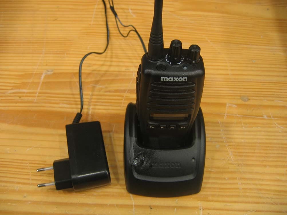
RXUSP7402
Jan 16, 2008UHF LMR
Equipment Class
TNF - Licensed Non-Broadcast Transmitter Held to Face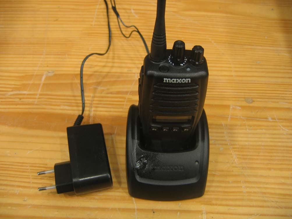
RXUSL7402
Jan 13, 2008UHF LMR
Equipment Class
TNF - Licensed Non-Broadcast Transmitter Held to Face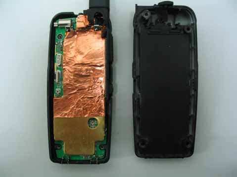
RXUSG9000
Oct 01, 2007FRS/GMRS Transceiver
Equipment Class
FRF - Part 95 Family Radio Face Held Transmitter
RXUSM2402
Feb 14, 2007Private Land Mobile Radio for Vehicle (UHF)
Equipment Class
TNB - Licensed Non-Broadcast Station Transmitter