RXUSP7402UHF LMR
Maxon CIC Corp.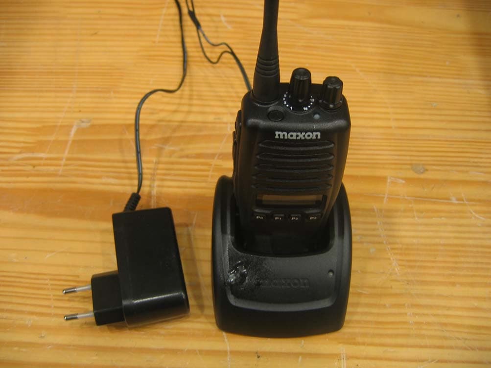
Click to zoom
Application Details
- Equipment Class
- TNF - Licensed Non-Broadcast Transmitter Held to Face
- Date of Grant
- Jan 16, 2008
- Application Purpose
- Original Equipment
- Date of Application
- Jan 16, 2008
- Equipment Note
- UHF LMR
- Frequency Range
- 406.10000000 - 470.00000000
- Company
- Maxon CIC Corp.
- Country
- South Korea
Documents & Files
Document Text
Text extracted from the exhibit documents filed with the FCC. Open a document above to read the original.
Users Manual
Function Description SP-7402 1/32 Function Description 2007-08-03 Synthesized Scanning Radio FCC RF EXPOSURE COMPLIANCE REQUIREMENTS FOR OCCUPATIONAL USEONLY The Federal Communications Commission (FCC), with its action in General Docket 93-62, November 7,1997, has adopted a safety standard for human exposure to Radio Frequency (RF) electromagnetic energy emitted by FCC regulated equipment. Maxon subscribes to the same safety standard for the use of its products. Proper operation of this radio will result in user exposure far below the Occupational Safety and Health Act (OSHA) and Federal Communications Commission limits. DO NOT transmit for more than 50% of total radio use time (50% duty cycle). Transmitting more than50% of the time can cause FCC RF exposure compliance requirements to be exceeded. This radio is NOT approved for use by the general population in an uncontrolled environment. This radio is restricted to occupational use, work related operations only where radio operator must have the knowledge to control the user’s exposure conditions for satisfying the higher exposure limit allowed for occupational use. When transmitting, hold the radio in a vertical position with its microphone 2 inches (5 cm) away from your mouth. The radio is transmitting when the red LED on the front of the radio is illuminated. You can cause the radio to transmit by pressing the PTT bar on the radio. These are required operating configurations for meeting FCC RF exposure compliance. Failure to observe these restrictions mean violation. . Safety Information The Federal Communications Commission (FCC), with its action in General Docket 93-62, March 13, 1997, has adopted a safety standard for human exposure to Radio Frequency (RF) electromagnetic energy emitted by FCC regulated equipment. Maxon subscribes to the same safety standard for the use of its products. Proper operation of this radio will result in user exposure far below the Occupational Safety and Health Act and Federal Communications Commission limits. WARNING - DO NOT hold the radio in such a manner that the antenna is next to, or touching, exposed parts of the body, especially the face or eyes, while transmitting. WARNING - DO NOT allow children to operate transmitter - equipped radio equipment. CAUTION - DO NOT operate the radio near unshielded electrical blasting caps or in an explosive atmosphere unless it is a type especially designed and qualified for such use. CAUTION - DO NOT press and hold the transmit switch (P-T-T) when not actually wishing to transmit. NOTE: This radio operates in FCC regulated frequency bands. All radios must be licensed by the FCC before use. Because this radio contains a transmitter, Federal law prohibits unauthorized use or adjustments of this radio. Function Description SP-7402 2/32 Table of Contents 1. Panel Description................................................................................................................ 4 (1) Front Panel................................................................................................................. 4 (2) LCD Display............................................................................................................... 5 (3) Display Option........................................................................................................... 6 2. Basic Functions................................................................................................................... 7 (1) Power On/Off & Volume Control.............................................................................. 7 (2) Receiving and Transmitting..................................................................................... 8 (3) User Set Mode......................................................................................................... 15 3. Emergency Function......................................................................................................... 16 (1) To transmit Emergency Call................................................................................... 16 (2) Effect......................................................................................................................... 16 (3) Emergency ID.......................................................................................................... 17 (4) Formation of the Emergency Call.......................................................................... 17 (5) Emergency Call Options......................................................................................... 17 4. Scan Function.................................................................................................................... 18 (1) Description............................................................................................................... 18 (2) Scan Type................................................................................................................. 18 (3) Nuisance Delete....................................................................................................... 18 (4) Scan List Edit........................................................................................................... 19 (5) Priority Channel / Lookback Channel Setting...................................................... 19 (6) TX Channel on Scan................................................................................................ 19 (7) Scan Operation Diagram........................................................................................ 20 5. Signaling Function............................................................................................................ 21 (1) Signaling Type & Transmission............................................................................. 21 (2) Signaling Functions and Receiving...................................................................... 23 (3) Signaling Operation Example.......................…
Text truncated - open the document above for the full version.
Cover Letter(s)
RM 612, Starwood Plaza, 5439-1 Chongho Building, #7-61 Yangjea-Dong, Seocho-Gu, Seoul, 137-130, Korea TEL No : +82-2-3498-3060 FAX No : +82-2-3498-3115 January 9, 2008 Federal Communications Commision Equipment Authorization Branch 7435 Oakland Mills Road Columbia, MD 21046 In re : Maxon CIC Corp. FCC ID : RXUSP7402 Justification Letter for extended frequency range use Gentlemen : We, Maxon CIC Corp., advices that SP7402 Handheld Transceiver has the design capability to be programmed and operated only for the frequency band 400-470 MHz. Especially we shall not program within the band 406-406.1 MHz. We, Maxon CIC Corp., also acknowledge that it is a violation of FCC rules for this device to be operated on unauthorized frequencies inside the USA. We, Maxon CIC Corp., acknowledge that this device will not be marketed to USA users with the frequency band which is not allowed by rule part as well. Please note that Licensed End users shall not have any access to external controls that will allow them to programmer the equipment. Equipment programming is the responsibility of Maxon CIC Corp. approved service agents. Sincerely, Hyun Koo, Kang Hyun Koo Kang, Senior Manager
Cover Letter(s)
RM 612, Starwood Plaza, 5439-1 Chongho Building, #7-61 Yangjea-Dong, Seocho-Gu, Seoul, 137-130, Korea TEL No : +82-2-3498-3060 FAX No : +82-2-3498-3115 January 9, 2008 Federal Communications Commision Equipment Authorization Branch 7435 Oakland Mills Road Columbia, MD 21046 In re : Maxon CIC Corp. FCC ID : RXUSP7402 Request for Confidentiality Gentlemen : In accordance with 0.457 and 0.459 of CFR 47, Maxon CIC Corp. Here by requests confidentiality of the Schematics, Block diagram, Part list and Operational description of the attached test report. These documents contain detailed system and equipment description and related information about the product which Maxon CIC Corp. Considers to be proprietary, confidential, and a custom design and, otherwise, would not release to the general public. Since this design is a basis from which future technological products will evolve, Maxon CIC Corp. Considers that this information would be of benefit to its competitors, and that the disclosure of the information in these documents would give competitors an unfair advantage in the market. Sincerely, Hyun Koo, Kang Hyun Koo Kang, Senior Manager
External Photos
FCC Test Report Maxon CIC Corp. Two Way Radio (LMR) SP7402 Report No: BWS-08-RF-0001 Page Number : 1 of 7 BWS TECH Inc. Appendix 3. External Photographs Data of Issue : January 4, 2008 Appendix 3. External Photographs of EUT 1. Front FCC Test Report Maxon CIC Corp. Two Way Radio (LMR) SP7402 Report No: BWS-08-RF-0001 Page Number : 2 of 7 BWS TECH Inc. Appendix 3. External Photographs Data of Issue : January 4, 2008 Appendix 3. External Photographs of EUT 2. Back FCC Test Report Maxon CIC Corp. Two Way Radio (LMR) SP7402 Report No: BWS-08-RF-0001 Page Number : 3 of 7 BWS TECH Inc. Appendix 3. External Photographs Data of Issue : January 4, 2008 Appendix 3. External Photographs of EUT 3. Left Side FCC Test Report Maxon CIC Corp. Two Way Radio (LMR) SP7402 Report No: BWS-08-RF-0001 Page Number : 4 of 7 BWS TECH Inc. Appendix 3. External Photographs Data of Issue : January 4, 2008 Appendix 3. External Photographs of EUT 4. Right Side FCC Test Report Maxon CIC Corp. Two Way Radio (LMR) SP7402 Report No: BWS-08-RF-0001 Page Number : 5 of 7 BWS TECH Inc. Appendix 3. External Photographs Data of Issue : January 4, 2008 Appendix 3. External Photographs of EUT 5. Top FCC Test Report Maxon CIC Corp. Two Way Radio (LMR) SP7402 Report No: BWS-08-RF-0001 Page Number : 6 of 7 BWS TECH Inc. Appendix 3. External Photographs Data of Issue : January 4, 2008 Appendix 3. External Photographs of EUT 6. Bottom FCC Test Report Maxon CIC Corp. Two Way Radio (LMR) SP7402 Report No: BWS-08-RF-0001 Page Number : 7 of 7 BWS TECH Inc. Appendix 3. External Photographs Data of Issue : January 4, 2008 Appendix 3. External Photographs of EUT 7. EUT with Battery Charger
ID Label/Location Info
FCC Test Report Maxon CIC Corp. Two Way Radio (LMR) SP7402 Report No: BWS-08-RF-0001 Page Number : 1 of 1 BWS TECH Inc. Appendix 2. FCC ID Label and Location Data of Issue : January 4, 2008 Appendix 2. FCC ID Label and location Product Label Sample with FCC ID Label information Following is a sample copy of the label that will be placed on the rear cabinet of the product. The FCC identifier is marked in the product label. The following FCC Warning statement will be described in the user manual. FCC Warning Label Location The label shown above shall be permanently affixed at a conspicuous location(cabinet out side) on the device and be readily visible to the user at the time purchase.(Labeling requirements per 2.925) Maxon CIC Corp. LMR(UHF Two Way Radio) Model : SP7402 FCC ID : RXUSP7402 IC:153B-SP7402 Caution Device must be restricted to occupation use to safety FCC RF exposure. See Instruction manual for s pecific operating requirement. FCC & IC LABEL Caution Serial Number
Internal Photos
FCC Test Report Maxon CIC Corp. Two Way Radio (LMR) SP7402 Report No: BWS-08-RF-0001 Page Number : 1 of 6 BWS TECH Inc. Appendix 4. Internal Photographs Data of Issue : January 4, 2008 Appendix 4. Internal Photographs of EUT 1. Top of Main Board FCC Test Report Maxon CIC Corp. Two Way Radio (LMR) SP7402 Report No: BWS-08-RF-0001 Page Number : 2 of 6 BWS TECH Inc. Appendix 4. Internal Photographs Data of Issue : January 4, 2008 Appendix 4. Internal Photographs of EUT 2. Bottom of Main Board FCC Test Report Maxon CIC Corp. Two Way Radio (LMR) SP7402 Report No: BWS-08-RF-0001 Page Number : 3 of 6 BWS TECH Inc. Appendix 4. Internal Photographs Data of Issue : January 4, 2008 Appendix 4. Internal Photographs of EUT 3. Top of Antenna Board FCC Test Report Maxon CIC Corp. Two Way Radio (LMR) SP7402 Report No: BWS-08-RF-0001 Page Number : 4 of 6 BWS TECH Inc. Appendix 4. Internal Photographs Data of Issue : January 4, 2008 Appendix 4. Internal Photographs of EUT 4. Bottom of Antenna Board FCC Test Report Maxon CIC Corp. Two Way Radio (LMR) SP7402 Report No: BWS-08-RF-0001 Page Number : 5 of 6 BWS TECH Inc. Appendix 4. Internal Photographs Data of Issue : January 4, 2008 Appendix 4. Internal Photographs of EUT 5. Top of Cradle Board FCC Test Report Maxon CIC Corp. Two Way Radio (LMR) SP7402 Report No: BWS-08-RF-0001 Page Number : 6 of 6 BWS TECH Inc. Appendix 4. Internal Photographs Data of Issue : January 4, 2008 Appendix 4. Internal Photographs of EUT 6. Bottom of Cradle Board
RF Exposure Info
Report File No. : STROS-07-019-A1 Date of Issue : 2008-01-16 Page : 1 / 50 SAR TEST REPORT Equipment Under Test : Portable LMR Model No. : SP7402 Applicant : Maxon CIC Corp Address of Applicant : Chongho Building, #7-61 Yangjae-Dong, Seocho-Gu, Seoul, 137-130, Korea FCC ID RXUSP7402 Device Category : Portable Device Exposure Category : Occupational/Controlled Exposure Date of Receipt : 2007-11-16 Date of Test(s) : 2007-11-19 Date of Issue : 2008-01-16 Max. SAR : 2.19 W/kg (Head 50% Duty Cycle) 3.95 W/kg (Body 50 % Duty Cycle) Standards: FCC OET Bulletin 65 supplement C IEEE 1528, 2003 ANSI/IEEE C95.1, C95.3 In the configuration tested, the EUT complied with the standards specified above. Remarks: Te s t e d b y : Leo Kim 2008-01-16 Approved by : Albert Lim 2008-01-16 This report details the results of the testing carried out on one sample, the results contained in this test report do not relate to other samples of the same product. The manufacturer should ensure that all products in series production are in conformity with the product sample detailed in this report. This report may only be reproduced and distributed in full. If the product in this report is used in any configuration other than that detailed in the report, the manufacturer must ensure the new system complies with all relevant standards. Any mention of SGS Testing Korea Co., Ltd. or testing done by SGS Testing Korea Co., Ltd. in connection with distribution or use of the product described in this report must be approved by SGS Testing Korea Co., Ltd. in writing. Report File No. : STROS-07-019-A1 Date of Issue : 2008-01-16 Page : 2 / 50 Contents 1. General Information 1.1 Testing Laboratory........................................................................................... 3 1.2 Details of Applicant.......................................................................................... 3 1.3 Version of Report............................................................................................. 3 1.4 Description of EUT(s)....................................................................................... 3 1.5 Test Environment............................................................................................. 4 1.6 Operation description........................................................................................ 4 1.7 Evaluation procedures....................................................................................... 5 1.8 The SAR Measurement System............................................................................ 6 1.9 System Components.......................................................................................... 8 1.10 SAR System Verification.................................................................................... 9 1.11 Tissue Simulant Fluid for the Frequency Band.......................................................... 11 1.12 Test Standards and Limits.................................................................................. 12 2. Instruments List.................................................................................... 13 3. Summary of Results................................................................................ 14 APPENDIX A. Photographs of EUT & EUT’s Test Setup B. DASY4 SAR Report C. Uncertainty Analysis D. Calibration certificate Report File No. : STROS-07-019-A1 Date of Issue : 2008-01-16 Page : 3 / 50 1. General Information 1.1 Testing Laboratory SGS Testing Korea Co., Ltd. Wireless Div. 2FL, 18-34, Sanbon-dong, Gunpo-si, Gyeonggi-do, Korea 435-040 Telephone : +82 +31 428 5700 FAX : +82 +31 427 2371 Homepage : www.electrolab.kr.sgs.com 1.2 Details of Applicant Manufacturer : Maxon CIC Corp Address : Chongho Building, #7-61 Yangjae-Dong, Seocho-Gu, Seoul, 137-130, Korea Contact Person : Bong-cheol Kang Phone No. : 82-2-3498-3044 Fax No. : 82-2-3498-3113 1.3 Version of Report Version Number Date Revision 00 2007-12-20 Initial issue 01 2008-01-16 Revision 1 1.4 Description of EUT(s) EUT Type : Portable LMR Model : SP7402 Serial Number : 07 11 000002 Mode of Operation : LMR Body worn Accessory : Belt Clip Tx Frequency Range : 400.025 MHz ~ 469.7875 MHz Antenna :External Max. Conducted RF Power : 3.93 W Battery Type : DC 7.4 V(Li-Polymer Battery) Report File No. : STROS-07-019-A1 Date of Issue : 2008-01-16 Page : 4 / 50 1.5 Test Environment Ambient temperature : 22 ~ 23 ° C Tissue Simulating Liquid : 22 ~ 23 ° C Relative Humidity : 40 ~ 60 % 1.6 Operation Configuration Reference Positions for Handheld Radio Transmitters In general handheld radio transmitters like GMRS/FRS/LMR devices are used in held to face position or with a speaker/microphone combination as body-worn configuration. Held to face position For held to face position the flat section of a SAM Phantom or a flat phantom is used. The center of the radiating structure is to set on the middle position of the flat phantom. The distance between sample and flat phantom is 2.5 cm, similar to the real using. For the measurement head tissue simulating liquid is used. Belt Clip/Holster Configuration Test configurations for body-worn operated EUTs are carried out while the belt-clip and/or holster is attached to the EUT and placed against a flat phantom in a regular configuration. An EUT with a headset output it tested with a headset connected to the device. Body dielectric parameters are used. There are two categories for accessories for body-worn operation configurations: 1. accessories not containing metallic components 2. accessories containing metallic components. When the EUT is equipped with accessories not containing metallic components the tests are done with the accessory that dictates the closest spacing to the body. For accessories containing metallic parts a test with each one is implemented. If the multiple accessories share an identical metallic component (e.g. the same metallic belt-clip used with different holsters with no other metallic compo…
Text truncated - open the document above for the full version.
Test Report
This report only responds to the tested sample and may not be reproduced, except in full, without written approval of the BWS TECH,Inc. BWS TECH Inc. www.bws.co.kr #611-1 Maesan-Ri, Mohyeon-Myeon, Yongin-Si, Gyeonggi-Do, 449-853 Korea TEL: +82 31 333 5997 FAX: +82 31 333 0017 January 4, 2008 (Date) Reviewed by TaeHyun, Nam January 4, 2008 (Date) Tested by CY-Choi FCC / INDUSTRY CANADA MEASUREMENT REPORT CERTIFICATION OF COMPLIANCE FCC PART90 & INDUSTRY CANADA RSS-119 CERTIFICATION PRODUCT : Two Way Radio Land Mobile Service (LMR) MODEL/TYPE NO : SP7402 FCC ID : RXUSP7402 TRADE NAME : APPLICANT : Maxon CIC Corp. Chongho Building, #7-61 Yangjae-Dong, Seocho-Gu, Seoul, 137-130, Korea Attn. : Hyun Koo Kang / Senior Manager CLASSIFICATION : TNF Licensed Non-Broadcast Station Transmitter Held to Face FCC Part 90 Private land mobile radio services RULE PART(S) : RSS-119 Land Mobile and Fixed Radio Transmitters and Receivers, 27.4 MHz to 960 MHz FCC PROCEDURE : Certification DATES OF TEST : November 26, 2007 to December 24, 2007 DATES OF ISSUE : January 4, 2008 TEST REPORT No. : BWS-08-RF-0001 TEST LAB. : BWS TECH Inc.(FCC Registration Number : 553281) This Two Way Radio SP7402 has been tested in accordance with the measurement procedures specified in ANSI C63.4-2003 and ANSI/TIA-603-B-2002 at the BWS TECH/EMC Test Laboratory and has been shown to be complied with the electromagnetic radiated emission limits specified in FCC Rule Part 90 and Industry Canada RSS-119. I attest to the accuracy of data. All measurement herein was performed by me or were made under my supervision. I assume full responsibility for the completeness of these measurements and vouch for the qualifications of all persons taking them. The results of testing in this report apply to the product/system, which was tested only. Other similar equipment may not necessarily produce the same results due to production tolerance and measurement uncertainties. FCC Test Report Maxon CIC Corp. Two Way Radio (LMR) SP7402 Report No: BWS-08-RF-0001 Page Number : 2 of 146 BWS TECH Inc. FCC Test Report Data of Issue : January 4, 2008 TABLE OF CONTENTS Pages 1. General Information 3 2. Description of Test Facility 4 3. Product Information 5 4. Summary of Test Results 8 5. Test Data 9 5.1. Power Line Conducted Emission 9 5.2. Radiated Emission Tests 13 5.3. RF Power Output (Conducted) 15 5.4. Modulation Characteristics – Audio Frequency Response 17 5.5. Modulation Characteristics – Audio Lowpass Filter Response 22 5.6. Modulation Characteristics – Modulation Limiting 24 5.7. Occupied Bandwidth 37 5.8. Spurious Emissions at Antenna Terminals 63 5.9. Field Strength of Spurious Radiation 73 5.10. Frequency Stability/Temperature Variation 75 5.11. Transient Frequency Behavior 128 6. Test Equipment List 146 Appendix 1. Test Setup Photos Appendix 2. FCC ID Label and location Appendix 3. External Photos of EUT Appendix 4. Internal Photos of EUT Appendix 5. Block Diagram Appendix 6. Schematics Appendix 7. Theory of Operation Appendix 8. Part List / Tune up Procedure Appendix 9. User Manual FCC Test Report Maxon CIC Corp. Two Way Radio (LMR) SP7402 Report No: BWS-08-RF-0001 Page Number : 3 of 146 BWS TECH Inc. FCC Test Report Data of Issue : January 4, 2008 FCC / INDUSTRY CANADA TEST REPORT Scope – Measurement and determination of electromagnetic emission(EME) of radio frequency devices including intentional radiators and/or unintentional radiators for compliance with the technical rules and regulations of the U.S Federal Communications Commission(FCC) 1. General Information Applicant Manufacturer Company Name Maxon CIC Corp. Company Address Chongho Building, #7-61 Yangjea-Dong, Seocho-Gu, Seoul, 137-130, Korea Phone/Fax Phone : +82-2-3498-3060 Fax : 02-3498-3115 Company Name Maxon CIC Thailand Co., Ltd(MCTL) Company Address 40/23 Moo 5 Rojana Industrial Park Tambol U-Thai, Amphur U-Thai Ayutthaya 13210 Thailand Phone/Fax Tel No. : +66-(0)35-719-498~501 Fax No. : +66-(0)35-719-492 z EUT Type Two Way Radio (LMR) z Model Number SP7402 z FCC Identifier RXUSP7402 z S/N 0710000001 z FCC Rule Part(s) FCC Part 90 Private land mobile radio services RSS-119 Land Mobile and Fixed Radio Transmitters and Receivers, 27.4 MHz to 960 MHz z FCC Classification TNF : Licensed Non-Broadcast Station Transmitter z Freq. Range 400 MHz ~ 470 MHz z Channel 256 Channels z Modulation Method FM z Emission Designator 11K0F3E, 16K0F3E z RF Power Output 1/4 Watt z Test Procedure ANSI C63.4-2003 and ANSI/TIA-603-B-2002 z Dates of Tests November 26, 2007 to December 18, 2007 z Place of Tests BWS TECH Inc.(FCC Registration Number : 553281) #611-1 Maesan-Ri, Mohyeon-Myeon, Yongin-Si, Gyeonggi-Do, 449-853 Korea TEL: +82 31 333 5997 FAX: +82 31 333 0017 z Test Report No. BWS-08-RF-0001 FCC Test Report Maxon CIC Corp. Two Way Radio (LMR) SP7402 Report No: BWS-08-RF-0001 Page Number : 4 of 146 BWS TECH Inc. FCC Test Report Data of Issue : January 4, 2008 2. Description of Test Facility The measurement for radiated and conducted emission test were conducted at the open area test site of BWS TECH Inc. facility located at #611-1 Maesan-Ri, Mohyeon-Myeon, Yongin-Si, Gyeonggi-Do, 449-853 Korea. The site is constructed in conformance with the requirements of the ANSI C63.4-2000 and CISPR Publication 16. The BWS TECH measurement facility has been filed to the Commission with the FCC for 3 and 10-meter site configurations. Detailed description of test facility was found to be in compliance with the requirements of Section 2.948 FCC Rules according to the ANSI C63.4-2000 and registered to the Federal Communications Commission (Registration Number : 553281 ). The measurement procedure described in American National Standard for Method of Measurement of Radio-Noise Emission from Low-Voltage Electrical and Electronic Equipment in the Range of 9kHz to 40GHz (ANSI C.63.4-2000) was used in determining radiated and conducted emissions from the Maxon C IC Corp. Two Way Radio Model : SP7402. FCC Test Report …
Text truncated - open the document above for the full version.
Test Setup Photos
FCC Test Report Maxon CIC Corp. Two Way Radio (LMR) SP7402 Report No: BWS-08-RF-0001 Page Number : 1 of 7 BWS TECH Inc. Appendix 1. Test Setup Photos Data of Issue : January 4, 2008 Appendix 1. Test Setup Photos 1. TX Test FCC Test Report Maxon CIC Corp. Two Way Radio (LMR) SP7402 Report No: BWS-08-RF-0001 Page Number : 2 of 7 BWS TECH Inc. Appendix 1. Test Setup Photos Data of Issue : January 4, 2008 Appendix 1. Test Setup Photos 2. RX Test FCC Test Report Maxon CIC Corp. Two Way Radio (LMR) SP7402 Report No: BWS-08-RF-0001 Page Number : 3 of 7 BWS TECH Inc. Appendix 1. Test Setup Photos Data of Issue : January 4, 2008 Appendix 1. Test Setup Photos 3. Extreme Condition Test FCC Test Report Maxon CIC Corp. Two Way Radio (LMR) SP7402 Report No: BWS-08-RF-0001 Page Number : 4 of 7 BWS TECH Inc. Appendix 1. Test Setup Photos Data of Issue : January 4, 2008 Appendix 1. Test Setup Photos 4. Power Line Conducted Emission Test (Front) FCC Test Report Maxon CIC Corp. Two Way Radio (LMR) SP7402 Report No: BWS-08-RF-0001 Page Number : 5 of 7 BWS TECH Inc. Appendix 1. Test Setup Photos Data of Issue : January 4, 2008 Appendix 1. Test Setup Photos 5. Power Line Conducted Emission Test (Back) FCC Test Report Maxon CIC Corp. Two Way Radio (LMR) SP7402 Report No: BWS-08-RF-0001 Page Number : 6 of 7 BWS TECH Inc. Appendix 1. Test Setup Photos Data of Issue : January 4, 2008 Appendix 1. Test Setup Photos 6. Radiated Emission Test (Less than 1GHz) FCC Test Report Maxon CIC Corp. Two Way Radio (LMR) SP7402 Report No: BWS-08-RF-0001 Page Number : 7 of 7 BWS TECH Inc. Appendix 1. Test Setup Photos Data of Issue : January 4, 2008 Appendix 1. Test Setup Photos 7. Radiated Emission Test (More than 1GHz)
Contact Information
Applicant
Hyun-Koo Kang(Manager)
Test Firm
BWS TECH INCCheol-Ho Lee
Technical Specifications
| # | Rule Parts | Frequency Range | Power Output | Emission | Tolerance |
|---|---|---|---|---|---|
| 8 | 9 | 406.1 MHz - 470 MHz | 3.926 W | 16K0F3E | 2.5 ppm |
Other Applications from Maxon CIC Corp.

RXUSM-2102E
Dec 26, 2013Mobile radio for vehicle
Equipment Class
TNB - Licensed Non-Broadcast Station Transmitter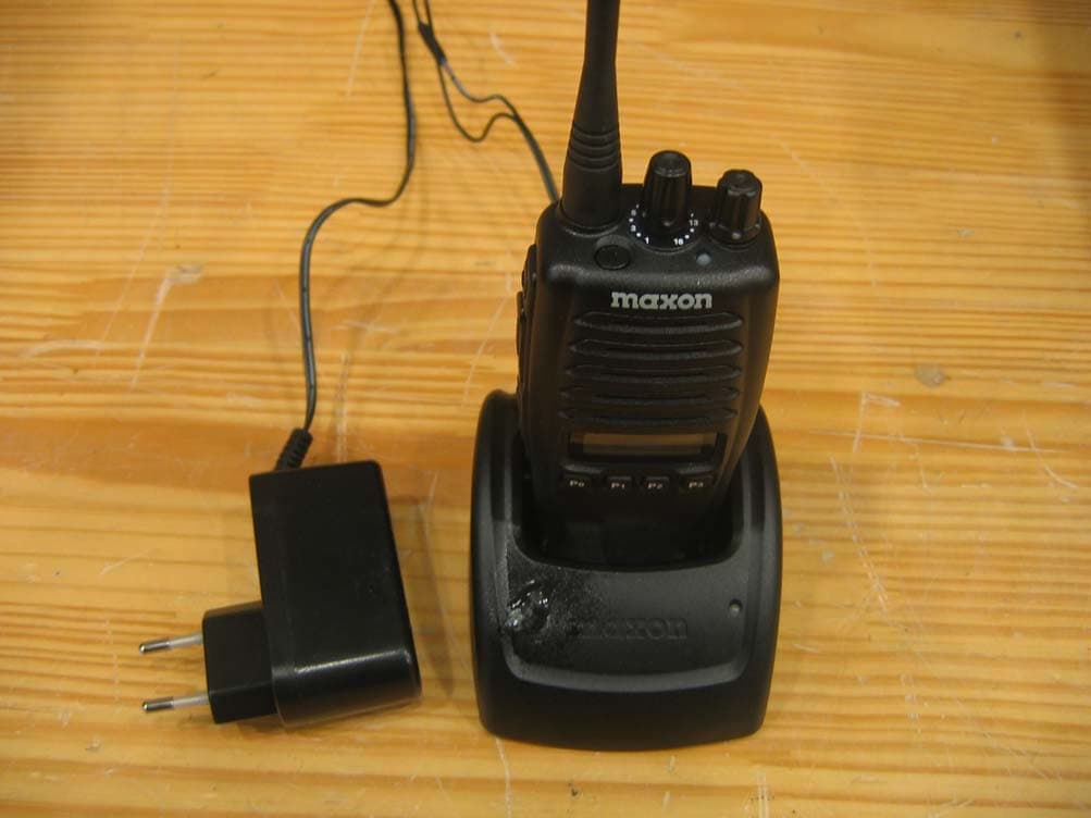
RXUSL7402
Jan 13, 2008UHF LMR
Equipment Class
TNF - Licensed Non-Broadcast Transmitter Held to Face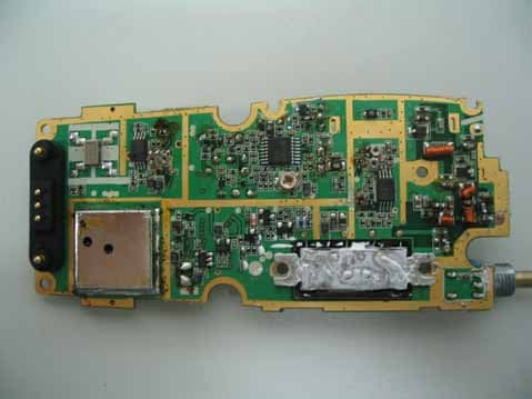
RXUSP6102
Nov 12, 2007Private Land Mobile Radio for Handheld (VHF)
Equipment Class
TNF - Licensed Non-Broadcast Transmitter Held to Face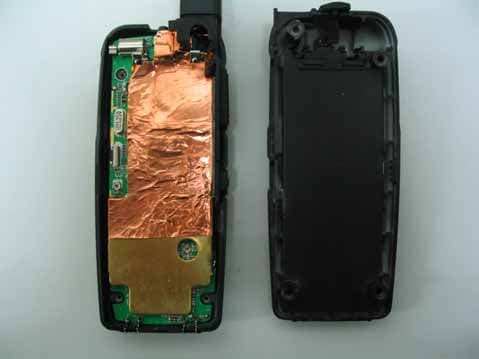
RXUSG9000
Oct 01, 2007FRS/GMRS Transceiver
Equipment Class
FRF - Part 95 Family Radio Face Held Transmitter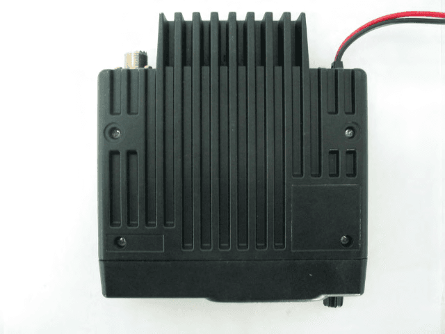
RXUSM2402
Feb 14, 2007Private Land Mobile Radio for Vehicle (UHF)
Equipment Class
TNB - Licensed Non-Broadcast Station Transmitter