RXUSP200V2SP200 V2 PTT VHF-H
Maxon CIC Corp.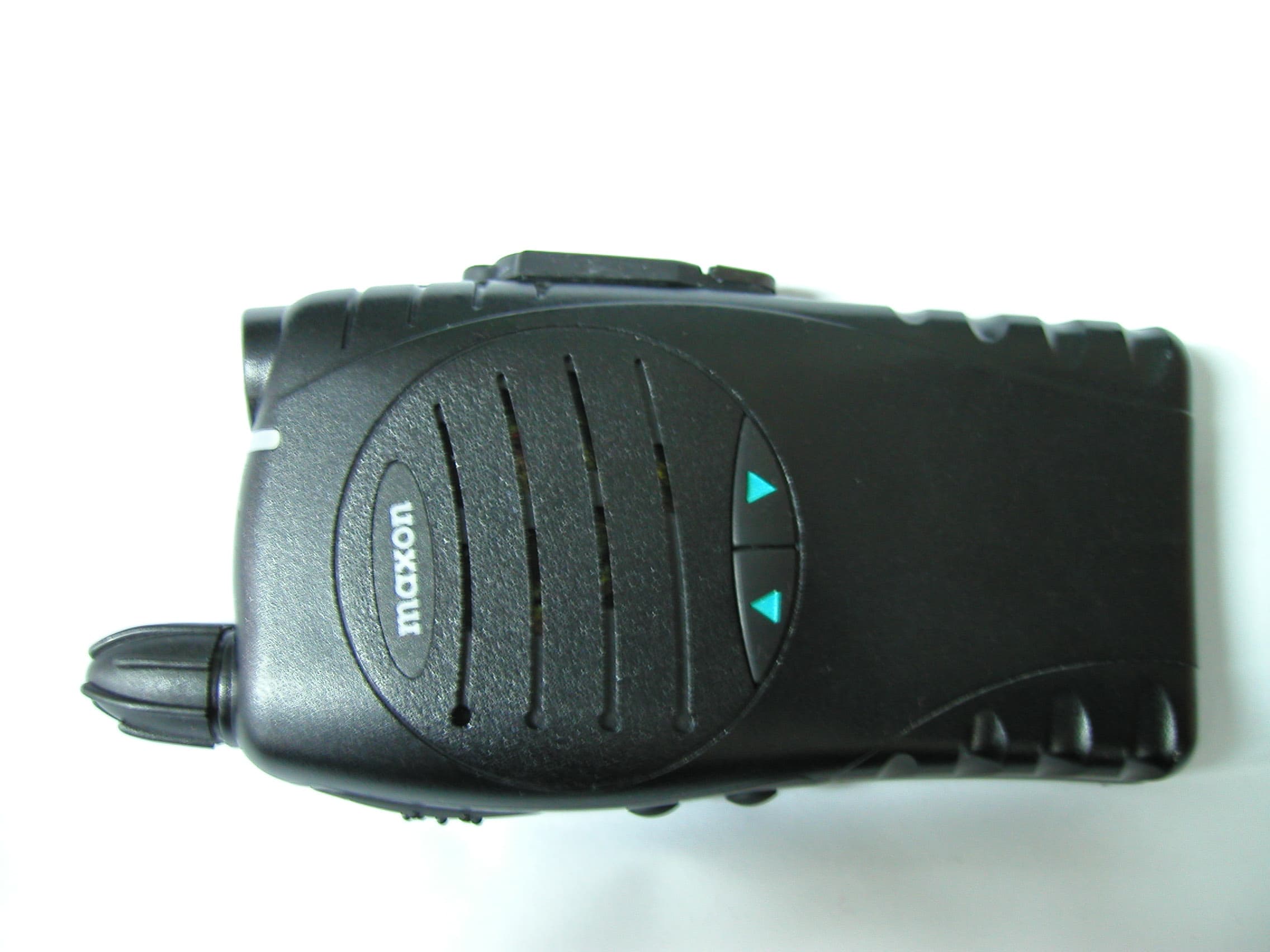
Click to zoom
Application Details
- Equipment Class
- TNF - Licensed Non-Broadcast Transmitter Held to Face
- Date of Grant
- May 03, 2005
- Application Purpose
- Original Equipment
- Date of Application
- Mar 15, 2005
- Equipment Note
- SP200 V2 PTT VHF-H
- Frequency Range
- 146.07500000 - 173.07500000
- Company
- Maxon CIC Corp.
- Country
- South Korea
Documents & Files
Document Text
Text extracted from the exhibit documents filed with the FCC. Open a document above to read the original.
Users Manual
Rhein Tech Laboratories, Inc. Report #: 2004187 360 Herndon Parkway FCC ID: RXUSP200V2 Suite 1400 Model: SP200 V2 Herndon, VA 20170 Standards: FCC Part 90 http://www.rheintech.com Date: March 15, 2005 . Page 49 of 61 APPENDIX J: USER’S MANUAL Please refer to the Operator’s Manual. 1 SP200 FCC RF EXPOSURE COMPLIANCE REQUIREMENTS FOR OCCUPATIONAL USE ONLY The Federal Communications Commission (FCC), with its action in General Docket 93-62, November 7, 1997, has adopted a safety standard for human exposure to Radio Frequency (RF) electromagnetic energy emitted by FCC regulated equipment. Maxon subscribes to the same safety standard for the use of its products. Proper operation of this radio will result in user exposure far below the Occupational Safety and Health Act (OSHA) and Federal Communications Commission limits. DO NOT transmit for more than 50% of total radio use time (50% duty cycle). Transmitting more than 50% of the time can cause FCC RF exposure compliance requirements to be exceeded. • This radio is NOT approved for use by the general population in an uncontrolled environment. This radio is restricted to occupational use, work related operations only where radio operator must have the knowledge to control the user’s exposure conditions for satisfying the higher exposure limit allowed for occupational use. • When transmitting, hold the radio in a vertical position with its microphone 1 inche (2.5 cm) away from your mouth. • The radio is transmitting when the red LED on the front of the radio is illuminated. You can cause the radio to transmit by pressing the PTT bar on the radio. • These are required operating configurations for meeting FCC RF exposure compliance. Failure to observe these restrictions mean violation. RF EXPOSURE COMPLIANEC AND CONTROL GUIDELINES AND OPERATING INSTRUCTIONS • To control your exposure and ensure compliance with the occupational/controlled environment exposure limits, always adhere to the following procedures. Guidelines: • Do not remove the RF Exposure Label from the device. Operating Instructions: • Hold the radio in a vertical position in front of face with the microphone (and the other parts of the radio, including the antenna) at least one inch (2.5 cm) away from the nose. Keeping the radio at the proper distance is important because RF exposures decrease with distance from the antenna. The antenna should be kept away from eyes. • When worn on the body, always place the radio in a Maxon Telecom approved clip, holder, holster, case, or body harness for this product. Using approved body-worn accessories is important because the use of Maxon Telecom or other manufacturer’s non-approved accessories may result in exposure levels which exceed the FCC’s occupational/controlled environment RF exposure limits. • Use only Maxon Telecom approved supplied or replacement antennas, batteries, and accessories. Use of non-Maxon Telecom approved antennas, batteries, and accessories may exceed the FCC RF exposure guidelines. 2 About Your SP-200 Radio Maxon's SP-200 Radio feature up to 13 groups and up to 16 channel operation per group for a total channel capacity of 199 channels of superior performance and reliability. Operation and functions for Maxon's SP-200 Radios are described in this manual. We urge you to thoroughly read this manual before operating the radio. Application of some of the functions described in this manual is determined by the system you use. Your Maxon Dealer will program your radio so that you have the greatest number of functions possible relative to your needs. Should you have questions regarding the operation of the radio please consult your Maxon Dealer. About Maxon America, Inc. Maxon America, Inc. designs and manufactures professional FM two-way radio equipment to serve a wide variety of communication needs. Maxon produces equipment for the Land Mobile Radio and Specialized Mobile Radio markets (business, industrial, government and public safety). Table of Contents Safety Information.................................................................. Unpacking Information.......................................................... SP-200 Features................................................................. Description of Radio Components......................................... Antenna Installation............................................................... Installing and Removing the Battery Pack............................... Attaching and Removing the Belt Clip.................................... Battery Charging and Care..................................................... SP-200 Operation.............................................................. Power On-Volume.................................................. Channel Select.......................................... Transmit.................................................................. Receive................................................................... Power Off.............................................................. Status Indicators and Audible Alert Tones............................. Scan Modes........................................................................... Normal Channel Scan............................................ Priority Channel Scan............................................. Other Scanning Features....................................................... . Look Back.......................................................................... Scan Channel Delete.............................................. CTCSS/DCS Scanning............................................ Normal Scan TX..................................................... Priority Scan TX..................................................... Priority Only TX..................................................... Receive Only Scan................................................. Scan List Edit ........................................................................ Licensing …
Text truncated - open the document above for the full version.
Users Manual
1 SP-200 FCC RF EXPOSURE COMPLIANCE REQUIREMENTS FOR OCCUPATIONAL USE ONLY The Federal Communications Commission (FCC), with its action in General Docket 93-62, November 7, 1997, has adopted a safety standard for human exposure to Radio Frequency (RF) electromagnetic energy emitted by FCC regulated equipment. Maxon subscribes to the same safety standard for the use of its products. Proper operation of this radio will result in user exposure far below the Occupational Safety and Health Act (OSHA) and Federal Communications Commission limits. DO NOT transmit for more than 50% of total radio use time (50% duty cycle). Transmitting more than 50% of the time can cause FCC RF exposure compliance requirements to be exceeded. This radio is NOT approved for use by the general population in an uncontrolled environment. This radio is restricted to occupational use, work related operations only where radio operator must have the knowledge to control the user’s exposure conditions for satisfying the higher exposure limit allowed for occupational use. When transmitting, hold the radio in a vertical position with its microphone 1 inches (2.5 cm) away from your mouth. The radio is transmitting when the red LED on the front of the radio is illuminated. You can cause the radio to transmit by pressing the PTT bar on the radio. These are required operating configurations for meeting FCC RF exposure compliance. Failure to observe these restrictions mean violation. RF EXPOSURE COMPLIANEC AND CONTROL GUIDELINES AND OPERATING INSTRUCTIONS • To control your exposure and ensure compliance with the occupational/controlled environment exposure limits, always adhere to the following procedures. Guidelines: • Do not remove the RF Exposure Label from the device. Operating Instructions: • Hold the radio in a vertical position in front of face with the microphone (and the other parts of the radio, including the antenna) at least one inch (2.5 cm) away from the nose. Keeping the radio at the proper distance is important because RF exposures decrease with distance from the antenna. The antenna should be kept away from eyes. • When worn on the body, always place the radio in a Maxon Telecom approved clip, holder, holster, case, or body harness for this product. Using approved body-worn accessories is important because the use of Maxon Telecom or other manufacturer’s non-approved accessories may result in exposure levels which exceed the FCC’s occupational/controlled environment RF exposure limits. • Use only Maxon Telecom approved supplied or replacement antennas, batteries, and accessories. Use of non-Maxon Telecom approved antennas, batteries, and accessories may exceed the FCC RF exposure guidelines. 2 About Your SP-200 Radio Maxon's SP-200 Radio feature up to 13 groups and up to 16 channel operation per group for a total channel capacity of 199 channels of superior performance and reliability. Operation and functions for Maxon's SP-200 Radios are described in this manual. We urge you to thoroughly read this manual before operating the radio. Application of some of the functions described in this manual is determined by the system you use. Your Maxon Dealer will program your radio so that you have the greatest number of functions possible relative to your needs. Should you have questions regarding the operation of the radio please consult your Maxon Dealer. About Maxon America, Inc. Maxon America, Inc. designs and manufactures professional FM two-way radio equipment to serve a wide variety of communication needs. Maxon produces equipment for the Land Mobile Radio and Specialized Mobile Radio markets (business, industrial, government and public safety). Table of Contents Safety Information.................................................................. Unpacking Information.......................................................... SP200 Specification................................................. SP-200 Features................................................................. Description of Radio Components......................................... Antenna Installation............................................................... Installing and Removing the Battery Pack............................... Attaching and Removing the Belt Clip.................................... Battery Charging and Care..................................................... SP-200 Operation.............................................................. Power On-Volume.................................................. Channel Select.......................................... Transmit.................................................................. Receive................................................................... Power Off.............................................................. Status Indicators and Audible Alert Tones............................. Scan Modes........................................................................... Normal Channel Scan............................................ Priority Channel Scan............................................. Other Scanning Features....................................................... . Look Back.......................................................................... Scan Channel Delete.............................................. CTCSS/DCS Scanning............................................ Normal Scan TX..................................................... Priority Scan TX..................................................... Priority Only TX..................................................... Receive Only Scan................................................. Scan List Edit ........................................................................ Licensing and Service Information........................................ Recycling/Disposal of Batteries............................................ Software Copyrights............................................................…
Text truncated - open the document above for the full version.
Cover Letter(s)
Rhein Tech Laboratories, Inc. Report #: 2004187 360 Herndon Parkway FCC ID: RXUSP200V2 Suite 1400 Model: SP200 V2 Herndon, VA 20170 Standards: FCC Part 90 http://www.rheintech.com Date: March 15, 2005 . Page 41 of 61 APPENDIX B: AGENCY AUTHORIZATION LETTER Please see the following page.
Cover Letter(s)
Rhein Tech Laboratories, Inc. Report #: 2004187 360 Herndon Parkway FCC ID: RXUSP200V2 Suite 1400 Model: SP200 V2 Herndon, VA 20170 Standards: FCC Part 90 http://www.rheintech.com Date: March 15, 2005 . Page 42 of 61 APPENDIX C: CONFIDENTIALITY REQUEST LETTER Please see the following page.
External Photos
Rhein Tech Laboratories, Inc. Report #: 2004187 360 Herndon Parkway FCC ID: RXUSP200V2 Suite 1400 Model: SP200 V2 Herndon, VA 20170 Standards: FCC Part 90 http://www.rheintech.com Date: March 15, 2005 . Page 52 of 61 APPENDIX L: EXTERNAL PHOTOGRAPHS PHOTOGRAPH 4: TOP Rhein Tech Laboratories, Inc. Report #: 2004187 360 Herndon Parkway FCC ID: RXUSP200V2 Suite 1400 Model: SP200 V2 Herndon, VA 20170 Standards: FCC Part 90 http://www.rheintech.com Date: March 15, 2005 . Page 53 of 61 PHOTOGRAPH 5: BOTTOM Rhein Tech Laboratories, Inc. Report #: 2004187 360 Herndon Parkway FCC ID: RXUSP200V2 Suite 1400 Model: SP200 V2 Herndon, VA 20170 Standards: FCC Part 90 http://www.rheintech.com Date: March 15, 2005 . Page 54 of 61 PHOTOGRAPH 6: FRONT
External Photos
Rhein Tech Laboratories, Inc. Report #: 2004187 360 Herndon Parkway FCC ID: RXUSP200V2 Suite 1400 Model: SP200 V2 Herndon, VA 20170 Standards: FCC Part 90 http://www.rheintech.com Date: March 15, 2005 . Page 55 of 61 PHOTOGRAPH 7: LEFT SIDE PHOTOGRAPH 8: RIGHT SIDE Rhein Tech Laboratories, Inc. Report #: 2004187 360 Herndon Parkway FCC ID: RXUSP200V2 Suite 1400 Model: SP200 V2 Herndon, VA 20170 Standards: FCC Part 90 http://www.rheintech.com Date: March 15, 2005 . Page 56 of 61 PHOTOGRAPH 9: BACK COVER
ID Label/Location Info
Rhein Tech Laboratories, Inc. Report #: 2004187 360 Herndon Parkway FCC ID: RXUSP200V2 Suite 1400 Model: SP200 V2 Herndon, VA 20170 Standards: FCC Part 90 http://www.rheintech.com Date: March 15, 2005 . Page 45 of 61 APPENDIX F: LABEL AND LABEL LOCATION PHOTOGRAPH 1: FCC ID LABEL AND RF WARNING LABEL LOCATIONS Please see the following pages for samples of these labels. RF Label Here FCC ID LABEL HERE FCC ID LABEL HERE RF LABEL HERE
Internal Photos
Rhein Tech Laboratories, Inc. Report #: 2004187 360 Herndon Parkway FCC ID: RXUSP200V2 Suite 1400 Model: SP200 V2 Herndon, VA 20170 Standards: FCC Part 90 http://www.rheintech.com Date: March 15, 2005 . Page 57 of 61 APPENDIX M: INTERNAL PHOTOGRAPHS PHOTOGRAPH 10: DIGITAL PCB INSIDE FRONT CASE Rhein Tech Laboratories, Inc. Report #: 2004187 360 Herndon Parkway FCC ID: RXUSP200V2 Suite 1400 Model: SP200 V2 Herndon, VA 20170 Standards: FCC Part 90 http://www.rheintech.com Date: March 15, 2005 . Page 58 of 61 PHOTOGRAPH 11: PCB FRONT
Internal Photos
Rhein Tech Laboratories, Inc. Report #: 2004187 360 Herndon Parkway FCC ID: RXUSP200V2 Suite 1400 Model: SP200 V2 Herndon, VA 20170 Standards: FCC Part 90 http://www.rheintech.com Date: March 15, 2005 . Page 59 of 61 PHOTOGRAPH 12: RF PCB BACK SIDE Rhein Tech Laboratories, Inc. Report #: 2004187 360 Herndon Parkway FCC ID: RXUSP200V2 Suite 1400 Model: SP200 V2 Herndon, VA 20170 Standards: FCC Part 90 http://www.rheintech.com Date: March 15, 2005 . Page 60 of 61 PHOTOGRAPH 13: RF PCB FRONT SIDE Rhein Tech Laboratories, Inc. Report #: 2004187 360 Herndon Parkway FCC ID: RXUSP200V2 Suite 1400 Model: SP200 V2 Herndon, VA 20170 Standards: FCC Part 90 http://www.rheintech.com Date: March 15, 2005 . Page 61 of 61 PHOTOGRAPH 14: RF PCB FRONT SIDE WITHOUT SHIELDS
RF Exposure Info
© 2005 Celltech Labs Inc. 1 of 20 Test Report S/N: 110804RXU-F587-S90V Test Date(s): January 18, 2005 Test Type: FCC/IC SAR Evaluation Performed By: Spencer Watson Compliance Technologist Celltech Labs Inc. Reviewed By: _____ Russell W. Pipe Senior Compliance Technologist Celltech Labs Inc. Celltech Labs Inc. declares under its sole responsibility that this wireless portable device has demonstrated compliance with the Specific Absorption Rate (SAR) RF exposure requirements specified in FCC 47 CFR §2.1093 and Health Canada’s Safety Code 6. The device was tested in accordance with the measurement standards and procedures specified in FCC OET Bulletin 65, Supplement C (Edition 01-01) and Industry Canada RSS-102 Issue 1 (Provisional) for the Occupational / Controlled Exposure environment. All measurements were performed in accordance with the SAR system manufacturer recommendations. I attest to the accuracy of data. All measurements were performed by me or were made under my supervision and are correct to the best of my knowledge and belief. I assume full responsibility for the completeness of these measurements and vouch for the qualifications of all persons taking them. This test report shall not be reproduced partially, or in full, without the prior written approval of Celltech Labs Inc. The results and statements contained in this report pertain only to the device(s) evaluated. DECLARATION OF COMPLIANCE SAR RF EXPOSURE EVALUATION Test Lab CELLTECH LABS INC. Testing and Engineering Services 1955 Moss Court Kelowna, B.C. Canada V1Y 9L3 Phone: 250-448-7047 Fax: 250-448-7046 e-mail: [email protected] web site: www.celltechlabs.com Applicant Information MAXON TELECOM CO., LTD. 12F., Sewon Venture Town Bldg., 705-18, Yeoksam-Dong Seoul, Korea FCC IDENTIFIER: RXUSP200V2 IC IDENTIFIER: 153-SP200V2 Model(s): SP200 V2 Rule Part(s): FCC 47 CFR §2.1093; IC RSS-102 Issue 1 (Provisional) Test Procedure(s): FCC OET Bulletin 65, Supplement C (Edition 01-01) Device Classification: Licensed Non-Broadcast Transmitter Held to Face (TNF) Device Description: Portable VHF PTT Radio Transceiver Modulation Type: FM (VHF) Tx Frequency Range: 146 - 174 MHz Max. RF Output Power Measured: 38.05 dBm Conducted (160.075 MHz) Antenna Type(s) Tested: Detachable Whip (P/N: ACC-102) Battery Type(s) Tested: NiMH 7.5 V, 1350 mAh (P/N: BTM100-01) Body-Worn Accessories Tested: Swivel Belt-Clip (Plastic with Metal Spring) Earbud with Lapel-Microphone Max. SAR Levels Evaluated: Face-held: 0.0620 W/kg (50% Duty Cycle) Body-worn: 0.109 W/kg (50% Duty Cycle) © 2005 Celltech Labs Inc. 2 of 20 Test Report S/N: 110804RXU-F587-S90V Test Date(s): January 18, 2005 Test Type: FCC/IC SAR Evaluation TABLE OF CONTENTS 1.0INTRODUCTION......................................................................3 2.0DESCRIPTION OF DUT............................................................. 3 3.0SAR MEASUREMENT SYSTEM................................................. 4 4.0MEASUREMENT SUMMARY...................................................... 5 5.0DETAILS OF SAR EVALUATION................................................ 6 6.0EVALUATION PROCEDURES.................................................... 6 7.0SYSTEM PERFORMANCE CHECK............................................. 7 8.0SIMULATED EQUIVALENT TISSUES.......................................... 8 9.0SAR SAFETY LIMITS............................................................... 8 10.0ROBOT SYSTEM SPECIFICATIONS............................................ 9 11.0PROBE SPECIFICATION.......................................................... 10 12.0PLANAR PHANTOM................................................................. 10 13.0VALIDATION PHANTOM........................................................... 10 14.0DEVICE HOLDER.................................................................... 10 15.0TEST EQUIPMENT LIST........................................................... 11 16.0MEASUREMENT UNCERTAINTIES............................................. 12-13 17.0REFERENCES........................................................................14 APPENDIX A - SAR MEASUREMENT DATA............................................... 15 APPENDIX B - SYSTEM PERFORMANCE CHECK DATA............................ 16 APPENDIX C - SYSTEM VALIDATION PROCEDURES................................. 17 APPENDIX D - PROBE CALIBRATION...................................................... 18 APPENDIX E - MEASURED FLUID DIELECTRIC PARAMETERS................... 19 APPENDIX F - SAR TEST SETUP & DUT PHOTOGRAPHS.......................... 20 Applicant: Maxon Telecom Co., Ltd. FCC ID: RXUSP200V2IC ID: 153-SP200V2 Model:SP200 V2 Portable FM VHF PTT Radio Transceiver 146 - 174 MHz 2005 Celltech Labs Inc. This document is not to be reproduced in whole or in part without the written permission of Celltech Labs Inc. 3 of 20 Test Report S/N: 110804RXU-F587-S90V Test Date(s): January 18, 2005 Test Type: FCC/IC SAR Evaluation This measurement report demonstrates compliance of the Maxon Telecom Co., Ltd. Model: SP200 V2 Portable FM VHF PTT Radio Transceiver FCC ID: RXUSP200V2 with the SAR (Specific Absorption Rate) RF exposure requirements specified in FCC 47 CFR §2.1093 (see reference [1]), and Health Canada Safety Code 6 (see reference [2]) for the Occupational / Controlled Exposure environment. The test procedures described in FCC OET Bulletin 65, Supplement C (Edition 01-01) (see reference [3]) and IC RSS-102 Issue 1 (Provisional) (see reference [4]), were employed. A description of the product and operating configuration, detailed summary of the test results, methodology and procedures used in the evaluation, equipment used, and the various provisions of the rules are included within this test report. FCC Rule Part(s) FCC 47 CFR §2.1093 IC Rule Part(s) RSS-102 Issue 1 (Provisional) Test Procedure(s) FCC OET Bulletin 65, Supplement C (Edition 01-01) Device Classification Licensed Non-Broadcast Transmitter Held to Face (TNF) Devic…
Text truncated - open the document above for the full version.
Test Report
Engineering and Testing for EMC and Safety Compliance 360 Herndon Parkway, Suite 1400 Herndon, VA 20170 Phone: 703-689-0368 Fax: 703-689-2056 CERTIFICATION APPLICATION REPORT FCC PART 90 Test Lab: Rhein Tech Laboratories, Inc. Phone: 703-689-0368 360 Herndon Parkway Fax: 703-689-2056 Suite 1400 Web Site: www.rheintech.com Herndon, VA 20170 Contact: [email protected] Applicant: Maxon Telecom Co., Ltd. 12F Sewon Venture Town Bldg., 705-18, Yeoksam-Dong, Seoul Kangnam-Ku, 135-080 South Korea Phone: 82-2-2008-1603 Fax: 82-2-2008-1600 Email: [email protected] Contact: JH Kim FCC ID: RXUSP200V2 REPORT DATE: March 15, 2005 MODEL: SP200 V2 RTL WORK ORDER NUMBER: 2004187 EQUIPMENT TYPE: PTT VHF-H RTL QUOTE NUMBER: QRTL04-399 FCC Classification: TNF – Licensed Non-Broadcast Transmitter Held to Face FCC Rule Part(s): Part 90: Private Land Mobile Radio Services Frequency Range (MHz) Output Power (W) Frequency Tolerance (ppm) Emission Designator 146.075-173.075 6.5 5 16K0F3E 146.075-173.075 6.5 5 11K0F3E We, the undersigned, hereby declare that the equipment tested and referenced in this report conforms to the identified standard(s) as described in this test report. No modifications were made to the equipment during testing in order to achieve compliance with these standards. Furthermore, there was no deviation from, additions to or exclusions from the FCC Part 2, FCC Part 90, ANSI C63.2, ANSI/TIA-603-B-2002, and ANSI/TIA/EIA 603-1. Signature: Date: March 15, 2005 Typed/Printed Name: Desmond A. Fraser Position: President Signature: Date: March 15, 2005 Typed/Printed Name: Daniel Baltzell Position: Test Engineer Rhein Tech Laboratories, Inc. Report #: 2004187 360 Herndon Parkway FCC ID: RXUSP200V2 Suite 1400 Model: SP200 V2 Herndon, VA 20170 Standards: FCC Part 90 http://www.rheintech.com Date: March 15, 2005 . Page 2 of 61 TABLE OF CONTENTS 1 GENERAL INFORMATION ...................................................................................................................................5 1.1 SCOPE .........................................................................................................................................................5 1.2 TEST FACILITY............................................................................................................................................5 1.3 RELATED SUBMITTAL(S)/GRANT(S) .........................................................................................................5 2 EQUIPMENT INFORMATION................................................................................................................................6 2.1 TEST SYSTEM DETAILS.............................................................................................................................6 2.2 WORST CASE CONFIGURATION OF TESTED SYSTEM..........................................................................7 3 FCC PART 2.1033(C)(8); DC VOLTAGES AND CURRENTS ..............................................................................8 4 RF POWER OUTPUT - §2.1046 ............................................................................................................................9 4.1 ANSI/TIA/EIA-603-2002, SECTION 2.2.1 TEST PROCEDURE ...................................................................9 4.2 RF POWER OUTPUT TEST EQUIPMENT ..................................................................................................9 4.3 RF POWER OUTPUT TEST DATA ............................................................................................................10 4.4 MODULATION CHARACTERISTICS - §2.1047 TEST PROCEDURE .......................................................11 4.5 MODULATION CHARACTERISTICS TEST EQUIPMENT.........................................................................11 5 FCC PART 2 §2.1047(A): MODULATION CHARACTERISTICS - AUDIO FREQUENCY RESPONSE.............11 5.1 TEST PROCEDURE...................................................................................................................................11 5.2 TEST DATA ................................................................................................................................................12 6 FCC PART 2 §2.1047(A): MODULATION CHARACTERISTICS - AUDIO LOW PASS FILTER RESPONSE .13 6.1 TEST PROCEDURE...................................................................................................................................13 6.2 TEST DATA ................................................................................................................................................13 7 FCC PART 2 §2.1047(B): MODULATION CHARACTERISTICS - MODULATION LIMITING ..........................14 7.1 TEST PROCEDURE...................................................................................................................................14 7.2 TEST DATA ................................................................................................................................................14 8 OCCUPIED BANDWIDTH - §2.1049 ...................................................................................................................18 8.1 OCCUPIED BANDWIDTH - §2.1049 TEST PROCEDURE ........................................................................18 8.2 OCCUPIED BANDWIDTH TEST EQUIPMENT..........................................................................................18 8.3 OCCUPIED BANDWIDTH TEST DATA .....................................................................................................19 9 SPURIOUS EMISSIONS AT ANTENNA TERMINAL - §2.1051..........................................................................21 9.1 SPURIOUS EMISSIONS AT ANTENNA TERMINAL - §2.1051 TEST PROCEDURE ...............................21 9.2 SPURIOUS EMISSIONS AT ANTENNA TERMINAL TEST EQUIPMENT .................................................21 9.3 CONDUCTED SPURIOUS EMISSIONS TEST DATA........................…
Text truncated - open the document above for the full version.
Test Setup Photos
Rhein Tech Laboratories, Inc. Report #: 2004187 360 Herndon Parkway FCC ID: RXUSP200V2 Suite 1400 Model: SP200 V2 Herndon, VA 20170 Standards: FCC Part 90 http://www.rheintech.com Date: March 15, 2005 . Page 50 of 61 APPENDIX K: TEST PHOTOGRAPHS PHOTOGRAPH 2: RADIATED EMISSIONS FRONT VIEW Rhein Tech Laboratories, Inc. Report #: 2004187 360 Herndon Parkway FCC ID: RXUSP200V2 Suite 1400 Model: SP200 V2 Herndon, VA 20170 Standards: FCC Part 90 http://www.rheintech.com Date: March 15, 2005 . Page 51 of 61 PHOTOGRAPH 3: RADIATED EMISSIONS BACK VIEW
Contact Information
Applicant
Hyun-Koo Kang(Manager)
Technical Contact
Rhein Tech LaboratoriesDesmond Fraser
[email protected]703-689-0368
360 Herndon Parkway · Herndon, Virginia · United States
Non-Technical Contact
Rhein Tech LaboratoriesKathy Grzovic
[email protected]703-689-0368
Test Firm
Rhein Tech Laboratories, Inc.Rick McMurray
Technical Specifications
| # | Rule Parts | Frequency Range | Power Output | Emission | Tolerance |
|---|---|---|---|---|---|
| 2 | 9 | 146.075 MHz - 173.075 MHz | 6.5 W | 11K0F3E | 5 ppm |
Other Applications from Maxon CIC Corp.

RXUSM-2102E
Dec 26, 2013Mobile radio for vehicle
Equipment Class
TNB - Licensed Non-Broadcast Station Transmitter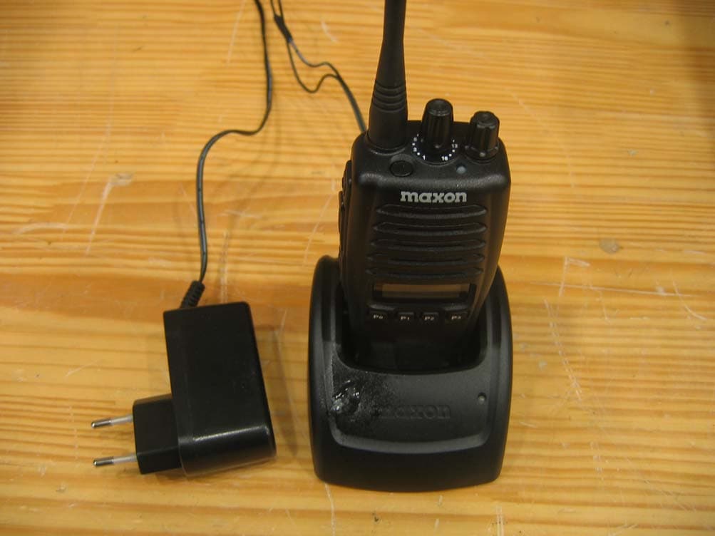
RXUSP7402
Jan 16, 2008UHF LMR
Equipment Class
TNF - Licensed Non-Broadcast Transmitter Held to Face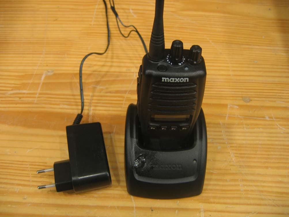
RXUSL7402
Jan 13, 2008UHF LMR
Equipment Class
TNF - Licensed Non-Broadcast Transmitter Held to Face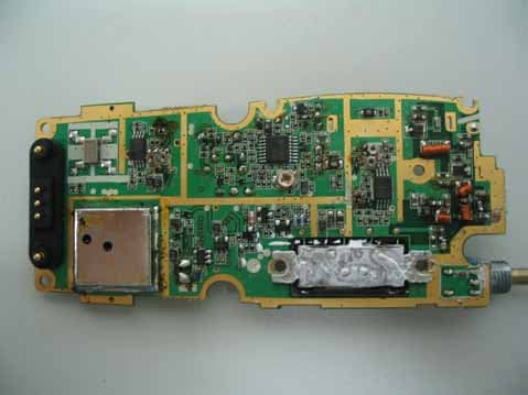
RXUSP6102
Nov 12, 2007Private Land Mobile Radio for Handheld (VHF)
Equipment Class
TNF - Licensed Non-Broadcast Transmitter Held to Face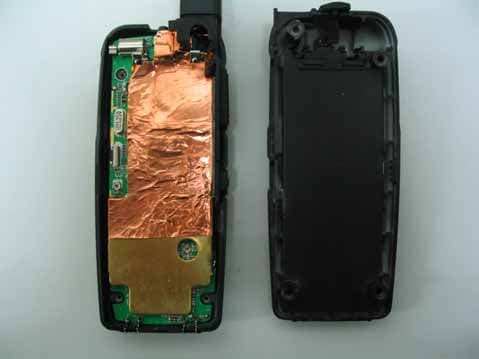
RXUSG9000
Oct 01, 2007FRS/GMRS Transceiver
Equipment Class
FRF - Part 95 Family Radio Face Held Transmitter