RYYEYTF3CSFTBluetooth Module
TAIYO YUDEN CO., LTD.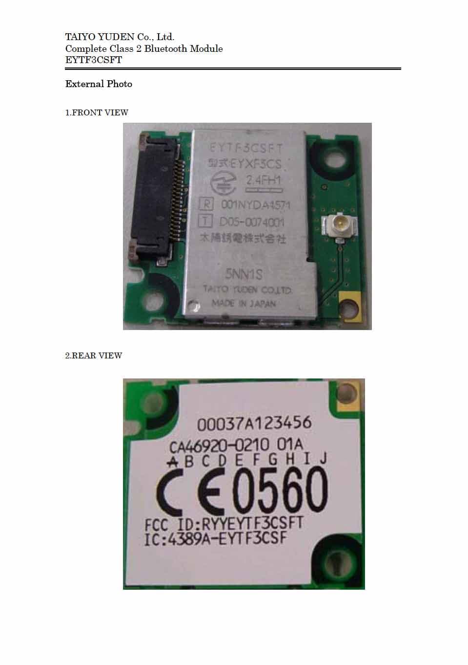
Click to zoom
Application Details
- Equipment Class
- DSS - Part 15 Spread Spectrum Transmitter
- Date of Grant
- Jan 23, 2006
- Application Purpose
- Original Equipment
- Date of Application
- Jan 23, 2006
- Equipment Note
- Bluetooth Module
- Frequency Range
- 2402.00000000 - 2480.00000000
- Company
- TAIYO YUDEN CO., LTD.
- Country
- Japan
Documents & Files
Document Text
Text extracted from the exhibit documents filed with the FCC. Open a document above to read the original.
Users Manual
16-Jan.-2006 Ver.1.5 TAIYO YUDEN Confidential & Tentative 1/44 TAIYO YUDEN EYTF3CSFT Bluetooth ® Module EYTF3CSFT (RF+Baseband (Class 2) USB) Data Report The Bluetooth ® word mark and logos are owned by the Bluetooth SIG, Inc. and any use of such marks by TAIYO YUDEN CO., LTD. is under license. In case you adopt this module and design some appliance, please ask for the latest specifications from the local sales office. 16-Jan.-2006 Ver.1.5 TAIYO YUDEN Confidential & Tentative 2/44 TAIYO YUDEN EYTF3CSFT Document constituent list Control name Control No. Document Page General Items HD-AG-A041081 1/3 - 3/3 Absolute maximum ratings HD-AM-A041081 1/1 Electrical characteristics HD-AE-A041081 1/3- 3/3 Electrical characteristics HD-AE-B041081 1/2 – 2/2 Electrical characteristics HD-AE-C041081 1/13 - 13/13 Electrical characteristics HD-AE-D041081 1/10 – 10/10 Circuit schematic HD-MC-A041081 1/1 Outline / Appearance HD-AD-A041081 1/4 - 4/4 Outline / Appearance HD-AD-B041081 1/1 Pin Layout HD-BA-A041081 1/3 – 3/3 Rev. record 1-Jul.-2004> Ver.0.5 Draft 20-Aug.-2004> Ver.0.6 Up-Date 30-Aug.-2004> Ver.0.9 Up-Date 5-Oct.-2004> Ver.1.0 Released 24-Nov.-2004> Ver.1.1 Up-Date 1-Dec.-2004> Ver.1.2 Up-Date 1-Apr.-2005> Ver.1.3 Up-Date 17-May.-2005> Ver.1.4 Up-Date 16-Jan.-2006> Ver.1.5 Up-Date 16-Jan.-2006 Ver.1.5 TAIYO YUDEN Confidential & Tentative 3/44 TAIYO YUDEN EYTF3CSFT Control No. HD-AG-A041081 (1/3) Control name General Items Scope This specification (“Specification”) applies to the hybrid IC “EYTF3CSTT” for use Bluetooth ® module (“Product”) manufacture by TAIYO YUDEN Co., Ltd. (“TAIYO YUDEN”) 1. Part Number: EYTF3CSTT (USB I/F Support) Digit3: Customer Code ex) T: TAIYO YUDEN Standard Digit8: Software Code ex) T: TAIYO YUDEN Standard Digit9: Hardware Code ex) T: TAIYO YUDEN Standard *Part number may be modified for mass production or other cases. Please see “m” for more information. 2. Function: Radio frequency transfer Module (power class 2). Bluetooth ® standard Ver 2.0+EDR conformity 3. Application: Note PC, PDA 4. Structure: Hybrid IC loaded with silicon monolithic semiconductor 5. Outline: Connector Type 6. Marking: TBD 7. Features: -Bluetooth ® 2.0+EDR conformity -USB Interface -Point-to-Multipoint (7 Slaves) -Encryption -Hold, Sniff and Park Mode -Supported Link Type: ACL (Not support Voice Over HCI) -AFH&Co-existence -EDR(Enhanced Data Rate) 8. Packing: Packaging method: Tray & aluminum moisture barrier bag Packaging unit: 40 pieces/tray Material of tray: PPE (Heat proof 135deg) Tray Specification: JEDEC STD No. 95-1 Section 10 Revision C 9. Terminal: Data input-output (20pin FPC/FFC Connector) RF input-output (Antenna Connector) 10. Mount: Mounted with M2 screw 11. Notes: a. Any question arising from this Specification shall be solved through mutual discussion by the parties hereof. b. This Product is not designed for radiation durable and should not be used under the circumstance of radiation. c. The operating conditions of this Product are as shown in this Specification. Please note that TAIYO YUDEN shall not be liable for a failure and/or abnormality which is caused by use under the conditions other than the operating conditions hereof. 16-Jan.-2006 Ver.1.5 TAIYO YUDEN Confidential & Tentative 4/44 TAIYO YUDEN EYTF3CSFT Control No. HD-AG-A041081 (2/3) Control name General Items d. This Product mentioned in this Specification is manufactured for use in Note PCs, PDAs and Cellular Phones. Before using this Product in any special equipment (such as medical equipment, space equipment, air craft, disaster prevention equipment), where higher safety and reliability are duly required, the applicability and suitability of this Product must be fully evaluated by the customer at its sole risk to ensure correct and safety operation of those special equipments. Also, evaluation of the safety function of this Product even for use in general electronics equipment shall be thoroughly made and when necessary, a protective circuit shall be added in design stage, all at the customer’s sole risk. e. TAIYO YUDEN warrants only that this Product is in conformity with this Specification for one year after purchase and shall in no event give any other warranty. f. The warranty period shall be one year. g. Communication between this Product and others might not be established nor maintained depending upon radio environment or operating conditions of this Product and other Bluetooth ® products. h. This Product is designed for use in products which comply with Bluetooth ® Specifications (ver 2.0+EDR) (“Bluetooth Specifications”). TAIYO YUDEN disclaims and is not responsible for any liability concerning infringement by this Product under any intellectual property right owned by third party in case the customer uses this Product in any product which does not comply with Bluetooth Specifications (the “non-complying products”). Furthermore, TAIYO YUDEN warrants only that this Product complies with this Specification and does not grant any other warranty including warranty for application of the non-complying products. i. TAIYO YUDEN dose not render updating or upgrading service for the firmware in the Module. j. In order to take tests for getting the certification of each country’s Radio Law with a device incorporating this module, it is necessary to make the software in Host to put the module into test condition. Please contact TAIYO YUDEN for farther details. k. Please evaluate adequately our module incorporated to your products before mass production. l. This Product operates in the unlicensed ISM band at 2.4GHz. In case this Product is used around the other wireless devices which operate in same frequency band of this Product, there is a possibility that interference occurs between this Product and such other devices. If such interference occurs, please stop the operation of other devices or relocate this Product before using this Product or do not use this Product around the other wireless devices. m. Part Numb…
Text truncated - open the document above for the full version.
Block Diagram
TAIYO YUDEN Co., Ltd. Complete Class 2 Bluetooth Module EYTF3CSFT Block Diagram DC3.3V Output Power Controller System Control Logic Unit Mixer1 ADC2ADC1 BPF2 Mixer2 BPF1 X2 Multiplier LPF3 DAC2 LPF2 Mixer4 DAC1 LPF1 Mixer3 Power Amp. (PA) Clock Diver2 Phase Detector +45/-45 Phase Shifter U100 BC04EXT RF + Baseband IC (RF, Modulator/Demodulator, Li nk Control, Main Control) Main Controller Data Control Unit Bus Interface Unit Memory Management Unit Clock Generator Unit Switch VCO Driver Amp. Clock Diver1 DC1.8V Frx : 2400.5 to 2478.5MHz IF=1.5MHz IF=1.5MHz 1MHz 1MHz 16MHz 16MHz A n inside of dotted line is an area of Blue tooth module was block off by shieldcase. Receiver Transmitter VCO/PLL Ftx : 2402 to 2480MHz F : 2402 to 2480MHz *f VCO * f VCO : TX : 1201 to 1240MHz 79channels(Channel spacing:0.5MHz) RX : 1200.25 to 1239.25MHz 79channels(Channel spacing:0.5MHz) CN100 RF connector DC3.3V GND Interface connector CN300 A ntenna Frequency Control Signal
Cover Letter(s)
Modular Approval Request (per DA 00-1407) FCC ID: __RYYEYTF3CSFT__ Items to be covered Answer from applicant 1. The modular transmitter must have its own RF shielding. Yes, this module has RF shielding. 2. The modular transmitter must have buffered modulation/data inputs (if such inputs are provided) to ensure that the module will comply with Part 15 requirements under conditions of excessive data rates or over-modulation. Yes, using IC has buffered circuit. 3. The modular transmitter must have its own power supply regulation. Yes, this module has power supply regulator. 4. The modular transmitter must comply with the antenna requirements of Section 15.203 and 15.204(c). The antenna must either be permanently attached or employ a “unique” antenna coupler (at all connections between the module and the antenna, including the cable).. Yes, this module has unique antenna coupler. 5. The modular transmitter must be tested in a stand-alone configuration, i.e., the module must not be inside another device during testing. This is intended to demonstrate that the module is capable of complying with Part 15 emission limits regardless of the device into which it is eventually installed. Yes, this testing is performed by stand-alone configuration. 6. The modular transmitter must be labeled with its own FCC ID number, and, if the FCC ID is not visible when the module is installed inside another device, then the outside of the device into which the module is installed must also display a label referring to the enclosed module. This exterior label can use wording such as the following: “Contains Transmitter Module FCC ID: XYZMODEL1” or “Contains FCC ID: XYZMODEL1.” Any similar wording that expresses the same meaning may be used. The Grantee may either provide such a label, an example of which must be included in the application for equipment authorization, or, must provide adequate instructions along with the module which explain this requirement. In the latter case, a copy of these instructions must be included in the application for equipment authorization. Yes, label of this module is put on PCB. For installer, these attentions are indicated in the manual. 7. The modular transmitter must comply with any specific rule or operating requirements applicable to the transmitter and the manufacturer must provide adequate instructions along with the module to explain any such requirements. A copy of these instructions must be included in the application for equipment authorization. For example, there are very strict operational and timing requirements that must be met before a transmitter is authorized for operation under Section 15.231. For instance, data transmission is prohibited, except for operation under Section 15.231(e), in which case there are separate field strength level and timing requirements. Compliance with these requirements must be assured. Yes, we provide adequate instructions. 8. The modular transmitter must comply with any applicable RF exposure requirements. For example, FCC Rules in Sections 2.1091, 2.1093 and specific Sections of Part 15, including 15.319(i), 15.407(f), 15.253(f) and 15.255(g), require that Unlicensed PCS, UNII and millimeter wave devices perform routine environmental evaluation for RF Exposure to demonstrate compliance. In addition, spread spectrum transmitters operating under Section 15.247 are required to address RF Exposure compliance in accordance with Section 15.247(b)(4). Modular transmitters approved under other Sections of Part 15, when necessary, may also need to address certain RF Exposure concerns, typically by providing specific installation and operating instructions for users, installers and other interested parties to ensure compliance. Yes, this module comply RF exposure requirements. For installer these attentions are indicated in the manual. Note: If compliance with one or more of the numbered requirements, listed above, cannot be demonstrated, it may be possible to obtain a “Limited Modular Approval” (LMA).
External Photos
TAIYO YUDEN Co., Ltd. Complete Class 2 Bluetooth Module EYTF3CSFT 1. FRONT VIEW with Antenna 2.REAR VIEW with Antenna
ID Label/Location Info
TAIYO YUDEN Co., Ltd. Complete Class 2 Bluetooth Module EYTF3CSFT 1. Label indication description ラベル表示内容 1)BD address number : 00037A◇◇◇◇◇◇ (Refer to 「Instruction for lot number」) BDアドレス番号 : 00037A◇◇◇◇◇◇(ロット番号解説書参照) 2)Fujitsu CA Diagram Number and Revision Status Number:CA46920-0210 01A 富士通殿CA図番、版数管理記号:CA46920-0210 01A 3)Revision ID:A B C D E F G H I J 改訂ID :A B C D E F G H I J 4)CE Marking for R&TTE : CE0560 5)FCC ID : RYYEYTF3CSFT 6)IC ID : 4389A-EYTF3CSF R1.5 21.4 5.5 2-R3.0 4.7 24.4 5.2 3.7 3.2 5.2 C A 4 6 9 2 0 - 0 2 1 0 0 1 A A B C D E F G H I J 0 0 0 3 7 A 0 0 A 0 0 0 F C C I D : R Y Y E Y T F 3 C S F T I C : 4 3 8 9 A - E Y T F 3 C S F Material :PET(UL969) / Label color:White / Printing :Black 材質 :PET(UL969)/ ラベル色 :白 / 印字 :黒 1) 2) 3) 4) 5) 6) TAIYO YUDEN Co., Ltd. Complete Class 2 Bluetooth Module EYTF3CSFT 2. Shielding case indication description シールドケース表示内容 TELEC 1)TELEC logo mark : Specified logo mark TELECロゴマーク : 規定ロゴマーク 2)TELEC qualification number : 001NYDA1571 TELEC認証番号 : 001NYDA1571 3)Product number for TELEC : EYXF3CS 申請設備の型式名 : EYXF3CS 4)Manufacture (Japanese) : 太陽誘電株式会社 Others その他 5)Actual indication 現品表示 : 「第二世代小電力データ通信システム無線設備」であることを表記 6)Taiyo Yuden product name : EYTF3CSFT 太陽誘電製品管理品名 : EYTF3CSFT 7)Product Lot number : Four digits (Refer to 「Instruction for lot number」) 製造Lot番号 : 4桁 (ロット番号解説表参照) 8)Manufacture (English) : TAIYO YUDEN CO.,LTD. 9)Country of manufacture : MADE IN JAPAN 10)JATE qualification number : D05-0074001 JATE 認証番号 : D05-0074001 2.4FH1 R 001NYDA1571 太陽誘電株式会社 EYTF3CSFT TAIYO YUDEN CO.,LTD. MADE IN JAPAN 1741 型式: EYXF3CS TD05-0074001 3) 6) 7) 2) 4) 8) 9) 5) 1) 10)
Internal Photos
TAIYO YUDEN Co., Ltd. Complete Class 2 Bluetooth Module EYTF3CSFT 1. FRONT VIEW with Antenna 2.REAR VIEW with Antenna
Test Report
TEST REPORT Report No. :5183F Page : 2 of 71 Table of Contents 1 TEST REPORT ................................................................................................................................................................... 4 2 GENERAL INFORMATION ................................................................................................................................................ 4 2.1 P RODUCT DESCRIPTION................................................................................................................................................. 4 2.2 S UMMARY OF TEST AND INSPECTION RESULT.................................................................................................................. 5 2.3 T EST METHODOLOGY..................................................................................................................................................... 5 2.4 T EST FACILITY............................................................................................................................................................... 5 3 SYSTEM TEST CONFIGURATION .................................................................................................................................... 6 3.1 J USTIFICATION............................................................................................................................................................... 6 3.2 O PERATING MODES........................................................................................................................................................ 7 3.3 L IST OF ACCESSORIES.................................................................................................................................................... 8 3.4 I NTERFACE CABLES....................................................................................................................................................... 8 3.5 S PECIAL TEST CONDITION.............................................................................................................................................. 9 3.6 E QUIPMENT MODIFICATIONS........................................................................................................................................... 9 3.7 C ONFIGURATION OF TESTED SYSTEM........................................................................................................................... 10 4 ANTENNA REQUIREMENT ............................................................................................................................................. 11 5 AC POWERLINE CONDUCTED EMISSION TEST.......................................................................................................... 12 5.1 T EST SETUP................................................................................................................................................................ 12 5.2 T EST INSTRUMENTATION.............................................................................................................................................. 12 5.3 C ONDUCTED EMISSION CALCULATION........................................................................................................................... 13 5.4 T EST RESULTS............................................................................................................................................................ 14 5.4.1 Transmitting mode ..................................................................................................................................... 14 5.4.2 Receiving mode ......................................................................................................................................... 17 6 RADIATED EMISSION TEST ........................................................................................................................................... 20 6.1 T EST SETUP................................................................................................................................................................ 20 6.2 R ADIATED EMISSION CALCULATION...............................................................................................................................21 6.3 T EST RESULTS............................................................................................................................................................ 22 6.3.1 Transmitting mode ..................................................................................................................................... 22 6.3.2 Receiving mode ......................................................................................................................................... 31 7 20DB BANDWIDTH .......................................................................................................................................................... 40 7.1 T EST SETUP................................................................................................................................................................ 40 7.2 T EST INSTRUMENT....................................................................................................................................................... 40 7.3 T EST RESULTS............................................................................................................................................................ 40 8 CARRIER FREQUENCY SEPARATION.......................................................................................................................... 41 8.1 T EST SETUP................................................................................................................................................................ 41 8.2 T EST INSTRUMENT.....................................................................................................................................…
Text truncated - open the document above for the full version.
Test Setup Photos
TAIYO YUDEN Co., Ltd. Complete Class 2 Bluetooth Module EYTF3CSFT TEST SET UP PHOTO 1. Photos of Radiated Measurement Axial Direction : XY-Plane Axial Direction : YZ-Plane Axial Direction : ZX-Plane TAIYO YUDEN Co., Ltd. Complete Class 2 Bluetooth Module EYTF3CSFT 2. Photos of Conducted Measurement
Contact Information
Applicant
Hideki Kato(Deputy General Manager)
Technical Contact
Taiyo Yuden Co., LtdKenzo Furuta
[email protected]+81 273608328
5607-2 Nakamuroda Harunamachi · Gunma-Gun Gunma · Japan
Test Firm
Taiyo Yuden Co., Ltd. EMC CenterKenzo Furuta
Technical Specifications
| # | Rule Parts | Frequency Range | Power Output |
|---|---|---|---|
| 1 | 15C | 2.40 GHz - 2.48 GHz | 1.28 mW |
Other Applications from TAIYO YUDEN CO., LTD.
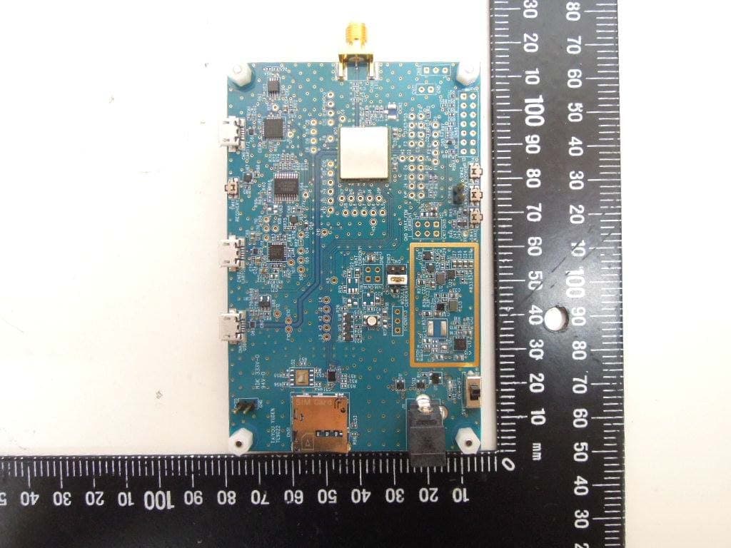
RYYCL5AD
Nov 17, 2020CatM1 Module
Equipment Class
PCB - PCS Licensed Transmitter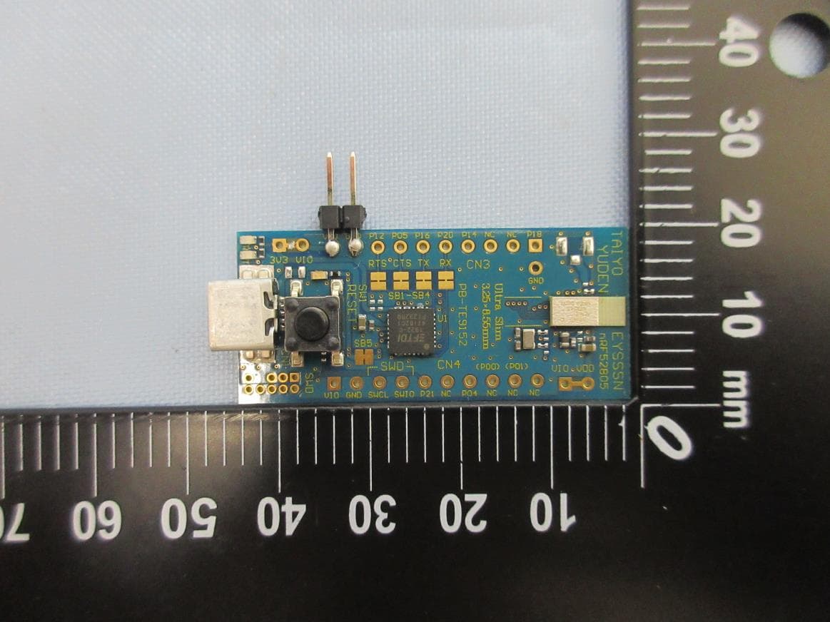
RYYEYSSSN
Nov 16, 2020Bluetooth low energy module
Equipment Class
DTS - Digital Transmission SystemRYYEYSPBN
Sep 07, 2020Bluetooth low energy/ ANT/ 802.15.4 Module
Equipment Class
DTS - Digital Transmission System
RYYEYSNCN
Feb 26, 2020Bluetooth low energy/ ANT/ 802.15.4 Module
Equipment Class
DTS - Digital Transmission System
RYYEYSNSN
Feb 16, 2020Bluetooth low energy/ ANT/ 802.15.4 Module
Equipment Class
DTS - Digital Transmission System