RYYWYSAAVDX7Wireless LAN Module
TAIYO YUDEN CO., LTD.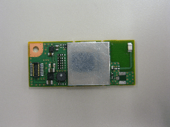
Click to zoom
Application Details
- Equipment Class
- DTS - Digital Transmission System
- Date of Grant
- Sep 27, 2011
- Application Purpose
- Original Equipment
- Date of Application
- Sep 25, 2011
- Equipment Note
- Wireless LAN Module
- Frequency Range
- 2422.00000000 - 2452.00000000
- Company
- TAIYO YUDEN CO., LTD.
- Country
- Japan
Documents & Files
Document Text
Text extracted from the exhibit documents filed with the FCC. Open a document above to read the original.
Users Manual
6-May.2011 Ver.0.6 TAIYO YUDEN Te n t a t i v e TAIYO YUDEN 1/20 WYSAAVDX7 Wireless LAN Module WYSAAVDX7 (IEEE802.11b/g/n) User Manual In case you adopt this module and design some appliance, please ask for the latest specifications from the local sales office. We wish the customer to request the Specification Report when the design for the mass production begins because the content of this Data Report might change without a previous notice to the customer. 6-May.2011 Ver.0.6 TAIYO YUDEN Te n t a t i v e TAIYO YUDEN 2/20 WYSAAVDX7 Document constituent list Control name Control No. Document Page General Items HD-AG-A100174 1/2 - 2/2 Absolute maximum ratings HD-AM-A100174 1/1 Electrical characteristics HD-AE-A100174 1/5 - 5/5 Circuit schematic HD-MC-A100174 1/1 Outline / Appearance HD-AD-A100174 1/1 Pin Layout HD-BA-A100174 1/1 Label Information HD-CA-A100174 1/1 Regulatory Information HD-CB-A100174 1/6 – 6/6 Rev. records 9-Mar.-2011> Ver.0.5 6-May-2011> Ver.0.6 6-May.2011 Ver.0.6 TAIYO YUDEN Te n t a t i v e TAIYO YUDEN 3/20 WYSAAVDX7 Control No. HD-AG-A100174 (1/2) Control name General Items Scope This specification (“Specification”) applies to the hybrid IC for use Wireless LAN module (“Product”) manufacture by TAIYO YUDEN Co., Ltd. (“TAIYO YUDEN”) 1. User Code: WYSAAVDX7 Digit3: Customer Code ex) S: TAIYO YUDEN Standard Digit8: Software Code ex) X: TAIYO YUDEN Standard Digit9: Hardware Code ex) 7: TAIYO YUDEN Standard * User Code may be modified for mass production or other cases. Please see “k” for more information. 2. Function: Radio frequency transfer Module. (IEEE802.11bgn standard conformity) 3. Application: PC peripheral, Handy terminal 4. Structure: Hybrid IC loaded with silicon monolithic and GaAs semiconductor Ability of lead free mounting at customer's assembly (Heat resistance of this Product) : Yes Containment of hazardous substance in this Product *This product conforms to RoHS Directive (2002/95/EC). 5. Outline: Stacking Connector Type 6. Marking: TBD 7. Features: -IEEE802.11bgn standard conformity -Interface: SDIO -Embedded MPU for reducing loads on host processor -Built-in EEPROM (MAC address) 8. Security: WEP (64/128), TKIP, AES, WPA, WPA2, WAPI 9. Packing: TBD 10. Terminal: Data input-output (20pin Stacking Connector) “Panasonic Electric Works Co., Ltd: AXK820145WG” RF input-output (Antenna) 11. Mount: with M2 screw 12. Notes: a. Any question arising from this Specification shall be solved through mutual discussion by the parties hereof. b. This Product is not designed for radiation durable and should not be used under the circumstance of radiation. c. The operating conditions of this Product are as shown in this Specification. Please note that TAIYO YUDEN shall not be liable for a failure and/or abnormality which is caused by use under the conditions other than the operating conditions hereof. d. This Product mentioned in this Specification is manufactured for use in consumer products. Before using this Product in any special equipment (such as medical equipment, space equipment, air craft, disaster prevention equipment), where higher safety and reliability are duly required, the applicability and suitability of this Product must be fully evaluated by the customer at its sole risk to ensure correct and safety operation of those special equipments. Also, evaluation of the safety function of this Product even for use in general electronics equipment shall be thoroughly made and when necessary, a protective circuit shall be added at design stage, all at the customer’s sole risk. 6-May.2011 Ver.0.6 TAIYO YUDEN Te n t a t i v e TAIYO YUDEN 4/20 WYSAAVDX7 Control No. HD-AG-A100174 (2/2) Control name General Items e. i) You are requested to fully check and confirm by the start of mass production of this Product that (1) no bug, defect or other failure is included in firmware incorporated in this Product (“Incorporated Software”), (2) no bug defect or other failure is caused by installation of this Product with Incorporated Software into customer’s products, and that Incorporated Software fully meets customer’s intended use, although TAIYO YUDEN sufficiently inspects or verifies quality of Incorporated Software. ii) Please note that TAIYO YUDEN is not responsible for any failure arising out of bugs or defects in Incorporated Software. f. TAIYO YUDEN warrants only that this Product is in conformity with this Specification for one year after purchase and shall in no event give any other warranty. g. Communication between this Product and others might not be established nor maintained depending upon radio environment or operating conditions of this Product and other ISM band at 2.4GHz products. h. In order to take tests for getting the certification of each country’s Radio Law with a device incorporating this module, it is necessary to make the software in Host to put the module into test condition. Please contact TAIYO YUDEN for further details. i. This Product operates in the unlicensed ISM band at 2.4GHz. In case this Product is used around the other wireless devices which operate in same frequency band of this Product, there is a possibility that interference occurs between this Product and such other devices. If such interference occurs, please stop the operation of other devices or relocate this Product before using this Product or do not use this Product around the other wireless devices. j. Please evaluate adequately our module incorporated to your products before mass production. k. User Code Modification Notice. User Code for sample modules or part numbers you see in this Specification are TAIYO YUDEN standard part numbers. When any modification is made to modules to meet requested specifications, the part number will carry a different part number, due to forfeit originality. Additionally, part numbers may be modified based on mass production stage or other related stages. Please contact TAIYO YUDEN to confirm whether your part number needs to be modified. Please see …
Text truncated - open the document above for the full version.
Attestation Statements
RF_734_00, Issue 1 Modular Approval Request FCC (per DA 00-1407) FCC ID: RYYWYSAAVDX7 Items to be covered Answer from applicant 1. The modular transmitter must have its own RF shielding. This module has RF shielding with metal case. Refer to external photo. 2. The modular transmitter must have buffered modulation/data inputs (if such inputs are provided) to ensure that the module will comply with Part 15 requirements under conditions of excessive data rates or over-modulation. Using IC, model No. 88W8787, has buffered circuit. 3. The modular transmitter must have its own power supply regulation. This Module has its own regulator, model No. PAM2305 and PAM3101. Refer to Block diagram. 4. The modular transmitter must comply with the antenna requirements of Section 15.203 and 15.204(c). The antenna must either be permanently attached or employ a “unique” antenna coupler (at all connections between the module and the antenna, including the cable).. Yes, this module use ceramic chip antenna attached with solder. 5. The modular transmitter must be tested in a stand-alone configuration, i.e., the module must not be inside another device during testing. This is intended to demonstrate that the module is capable of complying with Part 15 emission limits regardless of the device into which it is eventually installed. Yes, this testing is performed by stand-alone configuration. 6. The modular transmitter must be labeled with its own FCC ID number, and, if the FCC ID is not visible when the module is installed inside another device, then the outside of the device into which the module is installed must also display a label referring to the enclosed module. This exterior label can use wording such as the following: “Contains Transmitter Module FCC ID: XYZMODEL1” or “Contains FCC ID: XYZMODEL1.” Any similar wording that expresses the same meaning may be used. The Grantee may either provide such a label, an example of which must be included in the application for equipment authorization, or, must provide adequate instructions along with the module which explain this requirement. In the latter case, a copy of these instructions must be included in the application for equipment authorization. The label of this module with its own FCC ID is put on PCB. Exterior label instruction to installer of this module is provided in user manual. 7. The modular transmitter must comply with any specific rule or operating requirements applicable to the transmitter and the manufacturer must provide adequate instructions along with the module to explain any such requirements. A copy of these instructions must be included in the application for equipment authorization. For example, there are very strict operational and timing requirements that must be met before a transmitter is authorized for operation under Section 15.231. For instance, data transmission is prohibited, except for operation under Section 15.231(e), in which case there are separate field strength level and timing requirements. Compliance with these requirements must be assured. Instruction for operational requirements is provided in user manual. 8. The modular transmitter must comply with any applicable RF exposure requirements. For example, FCC Rules in Sections 2.1091, 2.1093 and specific Sections of Part 15, including 15.319(i), 15.407(f), 15.253(f) and 15.255(g), require that Unlicensed PCS, UNII and millimeter wave devices perform routine environmental evaluation for RF Exposure to demonstrate compliance. In addition, spread spectrum transmitters operating under Section 15.247 are required to address RF Exposure compliance in accordance with Section 15.247(b)(4). Modular transmitters approved under other Sections of Part 15, when necessary, may also need to address certain RF Exposure concerns, typically by providing specific installation and operating instructions for users, installers and other interested parties to ensure compliance. This module complies with RF exposure requirements and instruction for users is provided in the user manual. Note: If compliance with one or more of the numbered requirements, listed above, cannot be demonstrated, it may be possible to obtain a “Limited Modular Approval” (LMA). Name and surname of applicant (or authorized representative): Jiro Ogiwara Date: 19 May 2011 Signature:
External Photos
WYSAAVDX7_External Photo Upper side Lower side TAIYO YUDEN Confidential
ID Label/Location Info
WYSAAVDX7 Label Information Label Information 1) Type 㧦 WYSAAVDX7 2) Manufacturer 㧦 Taiyo Yuden Co.,Ltd. 3) R&TTE CE mark 㧦 Specified CE mark 4) FCC ID 㧦 RYYWYSAAVDX7 5) IC ID 㧦 4389B-WYSAAVDX7 6) Japan logo mark and ID 㧦 Specified logo mark and XXXXXXXXXXX 7) Country of Origin 㧦 China 8) MAC Address 㧦 XXXXXXXXXXXX 9) ARIB Actual Indication㧦Indicates that this device is “Second Generation Low Power Data Communication System” 10) Lot Number 㧦 XXXX 11) DC mark and Operating Input Voltage 㧦DC mark and 5.0V 12) User Code 㧦 XXXXXXXXX 13) UAE ID 㧦 TRA Logo and REGISTERED No and DEALER No 1) 2) 3) 4) 5) 6) 7) 8) 9) 10) 11) MODEL: WYSAAVDX7 FCC ID: RYYWYSAAVDX7 IC: 4389B-WYSAAVDX7 WYSAAVDX7-XE 2.4DS/OF4 5.0V Made in CHINATaiyo Yuden Co., Ltd. XXXXXXXXXXXXXXXXX 7.5 33.0 13.0 27.52.5 2.5 Φ6.0 5.5 3.0 User Code: TRA REGISTERED No: nnnnnn DEALER No: xxxxxxxxx R 001WWCA1266 3.5 12) User Code: XXXXXXXXX 13)
Internal Photos
WYSAAVDX7_Internal Photo Upper side Lower side TAIYO YUDEN Confidential
RF Exposure Info
Test report No. : 32AE0187-HO-A Page : 27 of 65 FCC ID : RYYWYSAAVDX7 Issued date : September 8, 2011 UL Japan, Inc. Head Office EMC Lab. 4383-326 Asama-cho, Ise-shi, Mie-ken 516-0021 JAPAN Telephone: +81 596 24 8116 Facsimile: +81 596 24 8124 APPENDIX 2 : SAR Measurement data 1. Evaluation procedure The evaluation was performed with the following procedure: Step 1: Measurement of the E-field at a fixed location above the ear point or central position of flat phantom was used as a reference value for assessing the power drop. Step 2: The SAR distribution at the exposed side of head or body position was measured at a distance of each device from the inner surface of the shell. The area covered the entire dimension of the antenna of EUT and the horizontal grid spacing was 15 mm x 15 mm (or 10mm x 10mm). Based on these data, the area of the maximum absorption was determined by spline interpolation. Step 3: Around this point found in the Step 2 (area scan) , a volume of 30mm x 30mm x 30mm or more was assessed by measuring 7 x 7 x 7 points at least. And for any secondary peaks found in the Step2 which are within 2dB of maximum peak and not with this Step3 (Zoom scan) is repeated. On the basis of this data set, the spatial peak SAR value was evaluated under the following procedure: (1). The data at the surface were extrapolated, since the center of the dipoles is 1mm(EX3DV3) away from the tip of the probe and the distance between the surface and the lowest measuring point is 1.3 mm. The extrapolation was based on a least square algorithm [4]. A polynomial of the fourth order was calculated through the points in z-axes. This polynomial was then used to evaluate the points between the surface and the probe tip. (2). The maximum interpolated value was searched with a straightforward algorithm. Around this maximum the SAR values averaged over the spatial volumes (1 g or 10 g) were computed by the 3D-Spline interpolation algorithm. The 3D- Spline is composed of three one-dimensional splines with the “Not a knot"-condition (in x, y and z-directions) [4], [5]. The volume was integrated with the trapezoidal-algorithm. One thousand points (10 x 10 x 10) were interpolated to calculate the average. (3). All neighboring volumes were evaluated until no neighboring volume with a higher average value was found. Step 4: Re-measurement of the E-field at the same location as in Step 1. Test report No. : 32AE0187-HO-A Page : 28 of 65 FCC ID : RYYWYSAAVDX7 Issued date : September 8, 2011 UL Japan, Inc. Head Office EMC Lab. 4383-326 Asama-cho, Ise-shi, Mie-ken 516-0021 JAPAN Telephone: +81 596 24 8116 Facsimile: +81 596 24 8124 2. Measurement data i) WLAN 11b WYSAAVDX7(H423A) Front 11b 1Mbps 2412MHz Communication System: WLAN 11a/b/g/n ; Communication System Band: WLAN 11b/g/n; Frequency: 2450 MHz;Duty Cycle: 1:1 Medium parameters used: f = 2450 MHz; σ = 2.01 mho/m; ε r = 51.4; ρ = 1000 kg/m 3 Phantom section: Flat Section Measurement Standard: DASY5 (IEEE/IEC/ANSI C63.19-2007) DASY5 Configuration Probe: EX3DV3 - SN3507; ConvF(7.61, 7.61, 7.61); Calibrated: 2011/03/16 Sensor-Surface: 2mm (Mechanical Surface Detection) Electronics: DAE4 Sn509; Calibrated: 2011/07/20 Phantom: ELI 4.0; Type: QDOVA001BA; Serial: xxxx Measurement SW: DASY52, Version 52.6 (1); Falt 0mm/dist=2.0mm (EX-Probe)/Area Scan (61x91x1): Measurement grid: dx=15mm, dy=15mm Maximum value of SAR (interpolated) = 1.632 mW/g Falt 0mm/dist=2.0mm (EX-Probe)/Zoom Scan (7x7x7) (7x8x7)/Cube 0: Measurement grid: dx=5mm, dy=5mm, dz=5mm Reference Value = 5.700 V/m; Power Drift = -0.14 dB Peak SAR (extrapolated) = 2.758 W/kg SAR(1 g) = 1.11 mW/g; SAR(10 g) = 0.432 mW/g Maximum value of SAR (measured) = 1.881 mW/g Date: 2011/09/01 Ambient Temp. : 23.5 degree.C. Liquid Temp.; 24.5 degree.C. Test report No. : 32AE0187-HO-A Page : 29 of 65 FCC ID : RYYWYSAAVDX7 Issued date : September 8, 2011 UL Japan, Inc. Head Office EMC Lab. 4383-326 Asama-cho, Ise-shi, Mie-ken 516-0021 JAPAN Telephone: +81 596 24 8116 Facsimile: +81 596 24 8124 WYSAAVDX7(H423A) Front 11b 1Mbps 2412MHz Communication System: WLAN 11a/b/g/n ; Communication System Band: WLAN 11b/g/n; Frequency: 2450 MHz;Duty Cycle: 1:1 Medium parameters used: f = 2450 MHz; σ = 2.01 mho/m; ε r = 51.4; ρ = 1000 kg/m 3 Phantom section: Flat Section Measurement Standard: DASY5 (IEEE/IEC/ANSI C63.19-2007) DASY5 Configuration Probe: EX3DV3 - SN3507; ConvF(7.61, 7.61, 7.61); Calibrated: 2011/03/16 Sensor-Surface: 2mm (Mechanical Surface Detection) Electronics: DAE4 Sn509; Calibrated: 2011/07/20 Phantom: ELI 4.0; Type: QDOVA001BA; Serial: xxxx Measurement SW: DASY52, Version 52.6 (1); Falt 0mm/dist=2.0mm (EX-Probe)/Z Scan (1x1x31): Measurement grid: dx=20mm, dy=20mm, dz=5mm Maximum value of SAR (measured) = 1.686 mW/g Test report No. : 32AE0187-HO-A Page : 30 of 65 FCC ID : RYYWYSAAVDX7 Issued date : September 8, 2011 UL Japan, Inc. Head Office EMC Lab. 4383-326 Asama-cho, Ise-shi, Mie-ken 516-0021 JAPAN Telephone: +81 596 24 8116 Facsimile: +81 596 24 8124 WYSAAVDX7(H423A) Rear 11b 1Mbps 2412MHz Communication System: WLAN 11a/b/g/n ; Communication System Band: WLAN 11b/g/n; Frequency: 2450 MHz;Duty Cycle: 1:1 Medium parameters used: f = 2450 MHz; σ = 2.01 mho/m; ε r = 51.4; ρ = 1000 kg/m 3 Phantom section: Flat Section Measurement Standard: DASY5 (IEEE/IEC/ANSI C63.19-2007) DASY5 Configuration Probe: EX3DV3 - SN3507; ConvF(7.61, 7.61, 7.61); Calibrated: 2011/03/16 Sensor-Surface: 2mm (Mechanical Surface Detection) Electronics: DAE4 Sn509; Calibrated: 2011/07/20 Phantom: ELI 4.0; Type: QDOVA001BA; Serial: xxxx Measurement SW: DASY52, Version 52.6 (1); Falt 0mm/dist=2.0mm (EX-Probe)/Area Scan (61x91x1): Measurement grid: dx=15mm, dy=15mm Maximum value of SAR (interpolated) = 0.103 mW/g Falt 0mm/dist=2.0mm (EX-Probe)/Zoom Scan (7x7x7) (7x8x7)/Cube 0: Measurement grid: dx=5mm, dy=5mm, dz=5mm Reference Value = 5.974 V/m; Power Drift = -0.14 dB Peak SAR (extrapolated) = 0.142 W/kg SAR(1 g) = 0.072 mW/g; SAR(10 g) = 0.041 mW/g …
Text truncated - open the document above for the full version.
RF Exposure Info
Test report No. : 32AE0187-HO-A Page : 50 of 65 FCC ID : RYYWYSAAVDX7 Issued date : September 8, 2011 UL Japan, Inc. Head Office EMC Lab. 4383-326 Asama-cho, Ise-shi, Mie-ken 516-0021 JAPAN Telephone: +81 596 24 8116 Facsimile: +81 596 24 8124 APPENDIX 4 : System specifications 1. Configuration and peripherals The DASY5 system for performing compliance tests consist of the following items: a) A standard high precision 6-axis robot (Stäubli RX family) with controller and software. An arm extension for accommodating the data acquisition electronics (DAE). b) An isotropic field probe optimized and calibrated for the targeted measurement. c) A data acquisition electronic (DAE), which performs the signal amplification, signal multiplexing, AD-conversion, offset measurements, mechanical surface detection, collision detection, etc. The unit is battery powered with standard or rechargeable batteries. The signal is optically transmitted to the EOC. d) The Electro-optical converter (EOC) performs the conversion between optical and electrical of the signals for the digital communication to the DAE and for the analog signal from the optical surface detection. The EOC is connected to the measurement server. e) The function of the measurement server is to perform the time critical tasks such as signal filtering, control of the robot operation and fast movement interrupts. f) The Light Beam used is for probe alignment. This improves the (absolute) accuracy of the probe positioning. g) A computer running WinXP and the DASY5 software. h) Remote control with teaches pendant and additional circuitry for robot safety such as warning lamps, etc. i) The phantom, the device holder and other accessories according to the targeted measurement. Test report No. : 32AE0187-HO-A Page : 51 of 65 FCC ID : RYYWYSAAVDX7 Issued date : September 8, 2011 UL Japan, Inc. Head Office EMC Lab. 4383-326 Asama-cho, Ise-shi, Mie-ken 516-0021 JAPAN Telephone: +81 596 24 8116 Facsimile: +81 596 24 8124 2. Specifications a)Robot TX60L Number of Axes : 6 Nominal Load : 2 kg Maximum Load : 5kg Reach : 920mm Repeatability : +/-0.03mm Control Unit : CS8c Programming Language : VAL3 Weight : 52.2kg Manuafacture : Stäubli Robotics b)E-Field Probe Model : EX3DV3 Serial No. : 3507 Construction : Symmetrical design with triangular core Built-in shielding against static charges PEEK enclosure material (resistant to organic solvents, e.g., glycol ether) Frequency : 10 MHz to > 6 GHz Linearity: ± 0.2 dB (30 MHz to 6 GHz) Directivity : +/-0.3 dB in HSL (rotation around probe axis) +/-0.5 dB in tissue material (rotation normal probe axis) Dynamic Range : 10uW/g to > 100 mW/g;Linearity +/-0.2 dB(noise: typically < 1uW/g) Dimensions : Overall length: 337 mm (Tip: 20 mm) Tip diameter: 2.5mm (Body: 12 mm) Typical distance from probe tip to dipole centers: 1 mm Application : Highprecision dosimetric measurement in any exposure scenario (e.g., very strong gradient fields).Only probe which enables compliance testing for frequencies up to 6GHz with precision of better 30%. Manufacture : Schimid & Partner Engineering AG c)Data Acquisition Electronic (DAE4) Features : Signal amplifier, multiplexer, A/D converter and control logic Serial optical link for communication with DASY5 embedded system (fully remote controlled) Two step probe touch detector for mechanical surface detection and emergency robot stop Measurement Range : -100 to +300 mV (16 bit resolution and two range settings: 4mV, 400mV) Input Offset voltage : < 5 μV (with auto zero) Input Resistance : 200 MΩ Input Bias Current : < 50 fA Battery Power : > 10 h of operation (with two 9.6 V NiMH accus) Dimension : 60 x 60 x 68 mm Manufacture : Schimid & Partner Engineering AG d)Electro-Optic Converter (EOC) Version : EOC 61 Descrption : for TX60 robot arm, including proximity sensor Manufacture : Schimid & Partner Engineering AG EX3DV3 E-field Probe Test report No. : 32AE0187-HO-A Page : 52 of 65 FCC ID : RYYWYSAAVDX7 Issued date : September 8, 2011 UL Japan, Inc. Head Office EMC Lab. 4383-326 Asama-cho, Ise-shi, Mie-ken 516-0021 JAPAN Telephone: +81 596 24 8116 Facsimile: +81 596 24 8124 e)DASY5 Measurement server Features : Intel ULV Celeron 400MHz 128MB chip disk and 128MB RAM 16 Bit A/D converter for surface detection system Vacuum Fluorescent Display Robot Interface Serial link to DAE (with watchdog supervision) Door contact port (Possibility to connect a light curtain) Emergency stop port (to connect the remote control) Signal lamps port Light beam port Three Ethernet connection ports Two USB 2.0 Ports Two serial links Expansion port for future applications Dimensions (L x W x H) : 440 x 241 x 89 mm Manufacture : Schimid & Partner Engineering AG f) Light Beam Switches Version : LB5 Dimensions (L x H) : 110 x 80 mm Thickness : 12 mm Beam-length : 80 mm Manufacture : Schimid & Partner Engineering AG g)Software Item : Dosimetric Assesment System DASY5 Type No. : SD 000 401A, SD 000 402A Software version No. : DASY52, Version 52.6 (1) Manufacture / Origin : Schimid & Partner Engineering AG h)Robot Controll Unit Weight : 70 Kg AC Input Voltage : selectable Manufacturer : Stäubli Robotics Test report No. : 32AE0187-HO-A Page : 53 of 65 FCC ID : RYYWYSAAVDX7 Issued date : September 8, 2011 UL Japan, Inc. Head Office EMC Lab. 4383-326 Asama-cho, Ise-shi, Mie-ken 516-0021 JAPAN Telephone: +81 596 24 8116 Facsimile: +81 596 24 8124 i)Phantom and Device Holder Phantom Type : SAM Twin Phantom V4.0 Description : The shell corresponds to the specifications of the Specific Anthropomorphic Mannequin (SAM) phantom defined in IEEE 1528 and IEC 62209-1. It enables the dosimetric evaluation of left and right hand phone usage as well as body mounted usage at the flat phantom region. A cover prevents evaporation of the liquid. Reference markings on the phantom allow the complete setup of all predefined phantom positions and measurement grids by teaching three points with the robot. Material : Vinylester, glass fiber r…
Text truncated - open the document above for the full version.
RF Exposure Info
Test report No. : 32AE0187-HO-A Page : 38 of 65 FCC ID : RYYWYSAAVDX7 Issued date : September 8, 2011 UL Japan, Inc. Head Office EMC Lab. 4383-326 Asama-cho, Ise-shi, Mie-ken 516-0021 JAPAN Telephone: +81 596 24 8116 Facsimile: +81 596 24 8124 APPENDIX 3 : System validation 1. System validation result Body 2450 Simulated Tissue Liquid Parameter confirmation Date Ambient Temp. [deg.c] Relative Humidity [%] Liquid type Liquid Temp. [deg.c] Measured Frequency [MHz] Parameters Target Value*1 Measured Deviation [%] Limit [%] εr 52.751.4-2.5+/-5 σ [mho/m] 1.952.013.1+/-5 εr: Relative Permittivity / σ : Coductivity *1 The Target value is a parameter defined in FCC OET 65 . 642450 DIELECTRIC PARAMETERS MEASUREMENT RESULTS 1-Sep24.5 MSL 2450 23.5 Date Ambient Temp. [deg.c] Relative Humidity [%] Liquid type Liquid Temp. [deg.c] Measured Frequency [MHz] Parameters Target Value*2 Measured Deviation [%] Limit*3 [%] εr 52.551.4-2.1+/-6 σ [mho/m] 1.952.013.1+/-6 εr: Relative Permittivity / σ : Coductivity *3 The limit is for deviation provided by manufacture. *2 The target value is the calibrated dipole Body TSL parameters. (D2450V2 SN:713, Measured Body TSL parameters) 642450 DIELECTRIC PARAMETERS MEASUREMENT RESULTS 1-Sep24.5 MSL 2450 23.5 System validation result Forward Power 250mWConversion 1WDeviationLimit MeasuredCalculation[%][%] 1-Se p2450.0012.7050.8051.90-2.1+/-10 *1 The taget value is the parameter defined in 1g SAR (normalizes to 1W) in manufacturer calibrated dipole (D2450V2 SN:713) SYSTEM VALIDATION Date SAR 1g [W/kg] Target 1W *1 Frequenc y [MHz] Test report No. : 32AE0187-HO-A Page : 39 of 65 FCC ID : RYYWYSAAVDX7 Issued date : September 8, 2011 UL Japan, Inc. Head Office EMC Lab. 4383-326 Asama-cho, Ise-shi, Mie-ken 516-0021 JAPAN Telephone: +81 596 24 8116 Facsimile: +81 596 24 8124 Body 2450MHz System Validation DATA / Dipole2.4GHz / Forward Conducted Power : 250mW Communication System: CW; Communication System Band: D2450 (2450.0 MHz); Frequency: 2450 MHz;Duty Cycle: 1:1 Medium parameters used: f = 2450 MHz; σ = 2.01 mho/m; ε r = 51.4; ρ = 1000 kg/m 3 Phantom section: Flat Section Measurement Standard: DASY5 (IEEE/IEC/ANSI C63.19-2007) DASY5 Configuration Probe: EX3DV3 - SN3507; ConvF(7.61, 7.61, 7.61); Calibrated: 2011/03/16 Sensor-Surface: 2mm (Mechanical Surface Detection) Electronics: DAE4 Sn509; Calibrated: 2011/07/20 Phantom: ELI 4.0; Type: QDOVA001BA; Serial: xxxx Measurement SW: DASY52, Version 52.6 (1); System Performance Check at Frequencies above 1 GHz/d=10mm, Pin=xx mW, dist=2.0mm (EX-Probe)/Area Scan (61x61x1): Measurement grid: dx=15mm, dy=15mm Maximum value of SAR (interpolated) = 19.681 mW/g System Performance Check at Frequencies above 1 GHz/d=10mm, Pin=xx mW, dist=2.0mm (EX-Probe)/Zoom Scan (7x7x7) (7x8x7)/Cube 0: Measurement grid: dx=5mm, dy=5mm, dz=5mm Reference Value = 100.0 V/m; Power Drift = -0.03 dB Peak SAR (extrapolated) = 26.628 W/kg SAR(1 g) = 12.7 mW/g; SAR(10 g) = 5.82 mW/g Maximum value of SAR (measured) = 19.454 mW/g Date: 2011/09/01 Ambient Temp. : 23.5 degree.C. Liquid Temp.; 24.5 degree.C. Test report No. : 32AE0187-HO-A Page : 40 of 65 FCC ID : RYYWYSAAVDX7 Issued date : September 8, 2011 UL Japan, Inc. Head Office EMC Lab. 4383-326 Asama-cho, Ise-shi, Mie-ken 516-0021 JAPAN Telephone: +81 596 24 8116 Facsimile: +81 596 24 8124 2. Validation uncertainty The uncertainty budget has been determined for the DASY5 measurement system according to the SPEAG documents[2] and is given in the following Table. Error Description Uncertainty value ± % Probability distribution divisor (ci) 1g Standard Uncertainty (1g) vi or veff Measurement System Probe calibration ±6.55 Normal 1 1 ±6.55 ∞ Axial isotropy of the probe ±4.7 Rectangular √3 1 ±2.7 ∞ Spherical isotropy of the probe ±9.6 Rectangular 0 0 0 ∞ Boundary effects ±1.0 Rectangular √3 1 ±1.2 ∞ Probe linearity ±4.7 Rectangular √3 1 ±2.7 ∞ Detection limit ±1.0 Rectangular √3 1 ±0.6 ∞ Readout electronics ±0.3 Normal 1 1 ±0.3 ∞ Response time 0 Rectangular √3 1 0 ∞ Integration time 0 Rectangular √3 1 0 ∞ RF ambient Noise ±1.0 Rectangular √3 1 ±1.7 ∞ RF ambient Reflections ±1.0 Rectangular √3 1 ±1.7 ∞ Probe Positioner ±0.8 Rectangular √3 1 ±0.5 ∞ Probe positioning ±6.7 Rectangular √3 1 ±3.9 ∞ Algorithms for Max.SAR Eval. ±2.0 Rectangular √3 1 ±1.2 ∞ Dipole Deviation of exp.dipole ±5.5 Rectangular √3 1 ±3.2 ∞ Dipole Axis to Liquid Distance ±2.0 Rectangular √3 1 ±1.2 ∞ Input power and SAR drift meas. ±3.4 Rectangular √3 1 ±2.7 ∞ Phantom and Setup Phantom uncertainty ±4.0 Rectangular √3 1 ±2.3 ∞ SAR correction ±1.9 Rectangular √3 1 ±1.1 Liquid conductivity (target) ±5.0 Rectangular √3 0.78 ±2.3 ∞ Liquid conductivity (meas.) ±5.0 Rectangular 1 0.26 ±1.3 ∞ Liquid permittivity (target) ±5.0 Rectangular √3 0.78 ±2.3 ∞ Liquid permittivity (meas.) ±5.0 Rectangular 1 0.23 ±1.2 ∞ Combined Standard Uncertainty ±11.01 Expanded Uncertainty (k=2) ±22.02 Test report No. : 32AE0187-HO-A Page : 41 of 65 FCC ID : RYYWYSAAVDX7 Issued date : September 8, 2011 UL Japan, Inc. Head Office EMC Lab. 4383-326 Asama-cho, Ise-shi, Mie-ken 516-0021 JAPAN Telephone: +81 596 24 8116 Facsimile: +81 596 24 8124 3. System Validation Dipole (D2450V2,S/N:713) Test report No. : 32AE0187-HO-A Page : 42 of 65 FCC ID : RYYWYSAAVDX7 Issued date : September 8, 2011 UL Japan, Inc. Head Office EMC Lab. 4383-326 Asama-cho, Ise-shi, Mie-ken 516-0021 JAPAN Telephone: +81 596 24 8116 Facsimile: +81 596 24 8124 Test report No. : 32AE0187-HO-A Page : 43 of 65 FCC ID : RYYWYSAAVDX7 Issued date : September 8, 2011 UL Japan, Inc. Head Office EMC Lab. 4383-326 Asama-cho, Ise-shi, Mie-ken 516-0021 JAPAN Telephone: +81 596 24 8116 Facsimile: +81 596 24 8124 Test report No. : 32AE0187-HO-A Page : 44 of 65 FCC ID : RYYWYSAAVDX7 Issued date : September 8, 2011 UL Japan, Inc. Head Office EMC Lab. 4383-326 Asama-cho, Ise-shi, Mie-ken 516-0021 JAPAN Telephone: +81 596 24 8116 Facsimile: +81 596 24 8124 Test report No. : 32AE0187-HO-A Page : 45 of 65 FCC ID : RYYWYSAAVDX7 Iss…
Text truncated - open the document above for the full version.
RF Exposure Info
Test report No. : 32AE0187-HO-A Page : 2 of 65 FCC ID : RYYWYSAAVDX7 Issued date : September 8, 2011 UL Japan, Inc. Head Office EMC Lab. 4383-326 Asama-cho, Ise-shi, Mie-ken 516-0021 JAPAN Telephone: +81 596 24 8116 Facsimile: +81 596 24 8124 SECTION 1: Customer information ................................................................................................................................................................... 3 SECTION 2: Equipment under test (E.U.T.) ..............................................................................................................................................…
Text truncated - open the document above for the full version.
Contact Information
Applicant
Hideki Kato(Deputy General Manager)
Technical Contact
Non-Technical Contact
Taiyo Yuden Co., Ltd. EMC CenterJiri Ogiwara
Test Firm
Taiyo Yuden Co., Ltd. EMC CenterJiro Ogiwara
Technical Specifications
| # | Rule Parts | Frequency Range | Power Output |
|---|---|---|---|
| 2 | 15C | 2.42 GHz - 2.45 GHz | 82.00 mW |
Other Applications from TAIYO YUDEN CO., LTD.
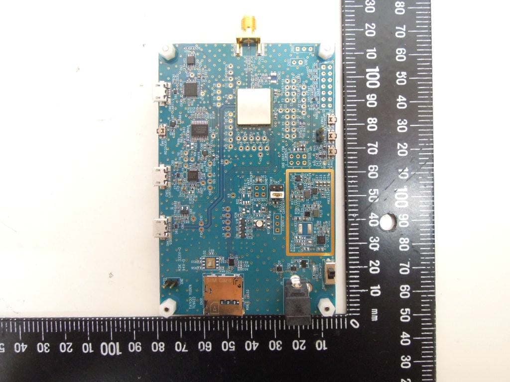
RYYCL5AD
Nov 17, 2020CatM1 Module
Equipment Class
PCB - PCS Licensed Transmitter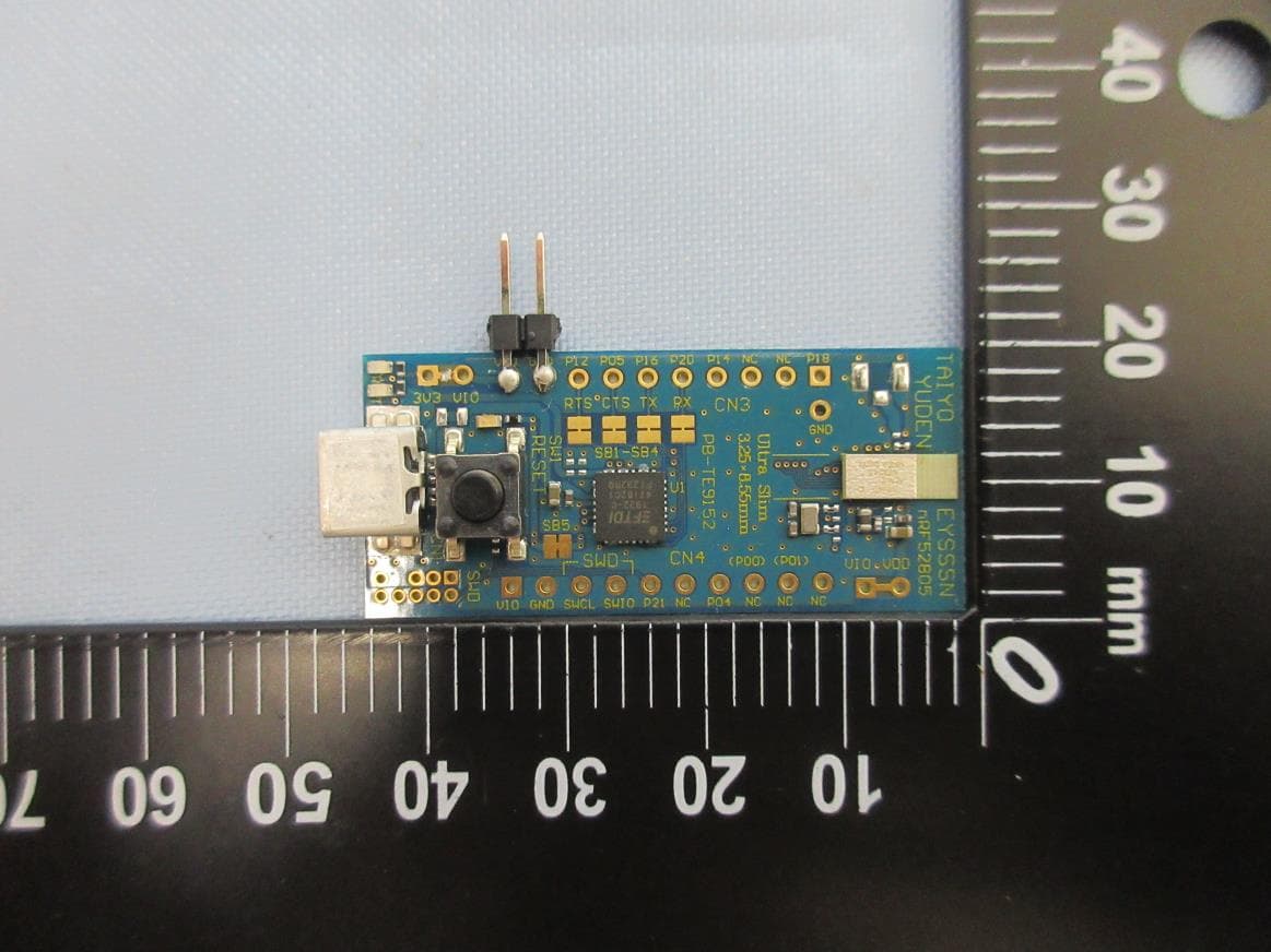
RYYEYSSSN
Nov 16, 2020Bluetooth low energy module
Equipment Class
DTS - Digital Transmission SystemRYYEYSPBN
Sep 07, 2020Bluetooth low energy/ ANT/ 802.15.4 Module
Equipment Class
DTS - Digital Transmission System
RYYEYSNCN
Feb 26, 2020Bluetooth low energy/ ANT/ 802.15.4 Module
Equipment Class
DTS - Digital Transmission System
RYYEYSNSN
Feb 16, 2020Bluetooth low energy/ ANT/ 802.15.4 Module
Equipment Class
DTS - Digital Transmission System