RYYWYSAAVDXB-EWireless Module
TAIYO YUDEN CO., LTD.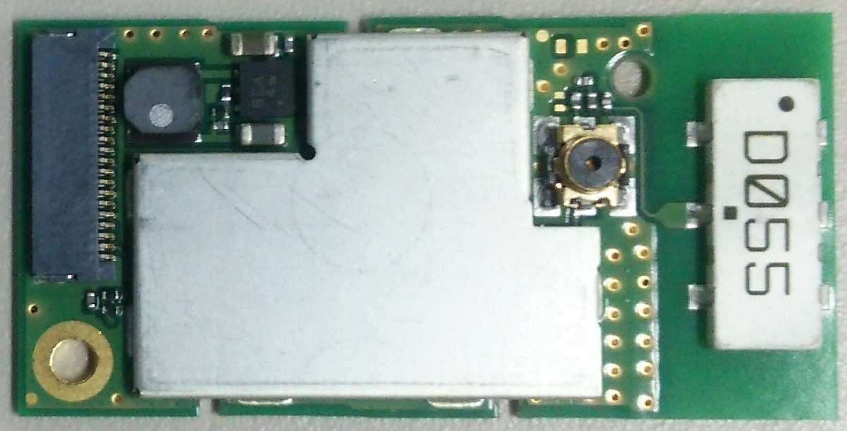
Click to zoom
Application Details
- Equipment Class
- DTS - Digital Transmission System
- Date of Grant
- Jul 28, 2015
- Application Purpose
- Original Equipment
- Date of Application
- Jul 28, 2015
- Equipment Note
- Wireless Module
- Frequency Range
- 2412.00000000 - 2462.00000000
- Company
- TAIYO YUDEN CO., LTD.
- Country
- Japan
Documents & Files
Document Text
Text extracted from the exhibit documents filed with the FCC. Open a document above to read the original.
Users Manual
9-Jul.2015 Ver.1.0 TAIYO YUDEN FCC ID: RYYWYSAAVDXB-E 1/16 TAIYO YUDEN CO., LTD. WYSAAVDXB-E Wireless LAN + Bluetooth ® Module WYSAAVDXB-E (IEEE802.11a/b/g/n + Bluetooth ® 3.0) Data Report The Bluetooth ® word mark and logos are owned by the Bluetooth SIG, Inc. and any use of such marks by TAIYO YUDEN CO., LTD. is under license. In case you adopt this module and design some appliance, please ask for the latest specifications from the local sales office. We wish the customer to request the Specification Report when the design for the mass production begins because the content of this Data Report might change without a previous notice to the customer. Please note that this Data Report should not be provided to end-users. 9-Jul.2015 Ver.1.0 TAIYO YUDEN FCC ID: RYYWYSAAVDXB-E 2/16 TAIYO YUDEN CO., LTD. WYSAAVDXB-E Document constituent list Control name Control No. Document Page General Items HD-AG-A140343 1/2 - 2/2 Absolute maximum ratings HD-AM-A140343 1/1 Electrical characteristics HD-AE-A140343 1/8 - 8/8 Circuit schematic HD-MC-A140343 1/1 Outline / Appearance HD-AD-A140343 1/1 Pin Layout HD-BA-A140343 1/1 Rev. records 9-Jul.-2015> Ver.1.0 Released. 9-Jul.2015 Ver.1.0 TAIYO YUDEN FCC ID: RYYWYSAAVDXB-E 3/16 TAIYO YUDEN CO., LTD. WYSAAVDXB-E Control No. HD-AG-A140343 (1/2) Control name General Items Scope This specification (“Specification”) applies to the hybrid IC for use Wireless LAN and Bluetooth ® module (“Product”) manufacture by TAIYO YUDEN CO., LTD. (“TAIYO YUDEN”) 1. Function: Radio frequency transfer Module.(IEEE802.11abgn and Bluetooth ® 3.0 standard conformity) 2. Application: PC peripheral, Handy terminal 3. Structure: Hybrid IC loaded with silicon monolithic and GaAs semiconductor Ability of lead free mounting at customer's assembly (Heat resistance of this Product): Yes Containment of hazardous substance in this Product *This product conforms to RoHS Directive. 4. Outline: FPC Connector Type 5. Features: -IEEE802.11abgn and Bluetooth ® 3.0 standard conformity -Interface: SDIO, PCM -Embedded MPU for reducing loads on host processor -Built-in EEPROM (MAC address) 6. Terminal: Data input-output (20pin FPC Connector) RF input-output (Antenna) 7. Mount: with M1 screw 8. Notes: a. Communication between this Product and others might not be established nor maintained depending upon radio environment or operating conditions of this Product and other ISM band at 2.4GHz and 5GHz products. b. This Product operates in the unlicensed ISM band at 2.4GHz and 5GHz. In case this Product is used around the other wireless devices which operate in same frequency band of this Product, there is a possibility that interference occurs between this Product and such other devices. If such interference occurs, please stop the operation of other devices or relocate this Product before using this Product or do not use this Product around the other wireless devices. c. Caution for Export Control This Product may be subject to governmental approvals, consents, licenses, authorizations, declarations, filings, and registrations for export or re-export of the Product, required by Japanese Foreign Exchange and Foreign Trade Law(including related laws and regulations) and/or any other country’s applicable laws or regulations related to export control. In case you will export or re-export this Product, you are strongly recommended to check and confirm, before exporting or re-exporting, necessary procedures for export or re-export of this Product which is required by applicable laws and regulations, and if necessary, you have to obtain necessary and appropriate approvals or licenses from governmental authority at your own risk and expense. 9-Jul.2015 Ver.1.0 TAIYO YUDEN FCC ID: RYYWYSAAVDXB-E 4/16 TAIYO YUDEN CO., LTD. WYSAAVDXB-E Control No. HD-AG-A140343 (2/2) Control name General Items d. FCC Regulatory Information This device complies with part 15 of the FCC Rules. Operation is subject to the following two conditions: (1) This device may not cause harmful interference, and (2) this device must accept any interference received, including interference that may cause undesired operation. a) Please notify certified ID by either one of the following method. -Contains Transmitter Module FCC ID: RYYWYSAAVDXB-E -Contains FCC ID: RYYWYSAAVDXB-E b) This product is only approved for use in Smart Headset; H725A. c) Please use the specified supply voltage in "Recommendation operating range" when installing this product. The final products must contain a power supply regulator and must ensure the applied voltage to this product is adjusted to always be within the operating voltage range. d) Please ensure and control your host product not to transmit on channels 12 and 13. e) Data transmission is inevitably initiated by software of host devices with the exception that several special packets are transmitted by the MAC. However, data transmission is terminated by end of packets in any cases. Therefore, it is RF transmitted only while packets are being transmitted. This modular transmitter automatically discontinues transmission in case of either absence of information to transmit or operational failure because RF parts will not be ON in neither cases. f) The device driver/firmware for this product is downloaded from a limited access web site provided by the device manufacturer and is implemented specifically for this product. The ID/password required to access the web site can be obtained after the conclusion of a contract with the device manufacturer. g) CAUTION: -Changes or modifications not expressly approved by the party responsible for compliance could void the use's authority to operate the equipment -To maintain compliance with FCC’s RF exposure guidelines, use only the supplied antenna. Unauthorized antenna, modification, or attachments could damage the transmitter and may violate FCC regulations. -This product is certified as type of the portable device with the FCC Rules. To maintain compliance with SAR requirement…
Text truncated - open the document above for the full version.
Users Manual
User's Guide Vie wing Images Using the Headset ..........12 Maintenance ...........................................................12 Troubleshooting ....................................................13 Specifications ..........................................................14 Int ellectual Property Rights ............................15 General Notes .........................................................15 Contac t List ..............................................................18 Contents Smart Headset MOVERIO Pro Included Items .......................................................2 Optional Items ........................................................2 Safet y Instructions................................................3 Par t Names and Functions ..............................6 Getting Ready .........................................................8 Tur ning On and Off ........................................... .. 10 Wearing the Product ..........................................10 2 Included Items Optional Items Headset Wear the headset to view images. ➡ “Wearing the Headset” p. 11 Controller (with controller hold- er) Operates the product. Battery packs (x2) Powers the product. ➡ “Charging the Battery” p. 8 AC adapter/AC cable Charges the product. The AC cable connector shape differs depending on where you bought the product. ➡ “Charging the Battery” p. 8 Shade Shades the product from too much exterior light. ➡ “Installing the Shade/Protective Shield/Lens Holder” p. 9 Protective shield Protects the product's lens from foreign objects. ➡ “Installing the Shade/Protective Shield/Lens Holder” p. 9 Inner pads (A/B/C) Attach inside the headset to adjust the headset to fit your head. The inner pad B is attached to the headset at the time of purchase. ➡ “Replacing the Inner Pad” p. 9 Lens holder Install lenses and attach them to the headset. This allows users who wear glasses to remove their glasses before wearing the headset. ➡ “Installing the Shade/Protective Shield/Lens Holder” p. 9 Armband Allows you to wear the controller on your arm. ➡ “Wearing the Controller” p. 10 Mono earphones with mic Outputs audio from the product, and inputs audio to the product. Hexagon wrench and screws (x2) Attaches the lens holder, shade, and protective shield. Hard carrying case BO-HC2000 Use this case when carrying or storing the product. Quad battery charger BO-QC2000 Allows you to charge four battery packs simultaneously. The battery packs are not included. Battery packs* (x2) BO-BP2000 Shade*/Protective shield* BO-SD2000 Inner pads (A/B/C)*/Lens hold- ers* (x2) BO-IP2000 Controller holder*/Armband* BO-PW2000 * Included with the product at time of purchase. 3 Safety Instructions For your safety, read the attached documents carefully to use the product correctly. After you have read the documents, save them for later reference. Safety symbols Warning This symbol indicates information that, if ig- nored, could possibly result in serious personal injury or even death due to incorrect handling. Caution This symbol indicates information that, if ig- nored, could possibly result in personal injury or physical damage due to incorrect handling. Warning Usage environment and condi- tion precautions Only use this product at the stated power-supply voltage. Only use the supplied AC cable and AC adapter. Using other power supply devices could result in heat, fire, explosion, malfunction, or liquid leakage. Take the following precautions when handling the plug. Failure to com- ply with these precautions could result in fire or electric shock. • Do not plug the AC adapter into an outlet being used by many other devices. • Do not insert the plug into a dusty outlet. • Insert the plug firmly into the outlet. • Do not hold the plug with wet hands. • Do not pull the power cable when disconnecting the plug. Do not use the supplied power cable if it is damaged. Doing so could result in fire or electric shock. • Do not modify the supplied power cable. • Do not place heavy objects on top of the supplied power cable. • Do not bend, twist, or pull the power cable with excessive force. • Keep the power cable away from hot electrical appliances. For your safety, unplug the product when it is not being used. The insulation may deteriorate, which may result in electric shock, fire, or malfunction. Do not touch the plug during a thunderstorm. Doing so could result in fire or electric shock. Do not leave this product in locations subject to temperatures beyond the specified operating range, such as cars with the windows closed, in direct sunlight, or in front of air-conditioning or heater outlets. Also, avoid locations subject to sudden changes in temperature. Doing so may result in deformation due to heat, fire, malfunction, failure, or dam- age. Do not use the product in locations where it may get wet or is subject to high levels of humidity such as in a bath or shower. Doing so could result in fire or electric shock. Do not place this product in locations subject to smoke, steam, high humidity, or dust such as kitchen counters or near humidifiers. Doing so may result in fire, electric shock, or deterioration in image quality. Do not cover this product with a cloth or similar material during use. Doing so may change the shape of the case through heat, or fire. Do not expose the camera lens to direct sunlight for a long time. Doing so may result in fire or explosion due to condensed beams of light from the lens. Warning Product usage precautions Do not start using this product at a high volume. Doing so may result in hearing impairment. Lower the volume before turning off the product, and gradually increase the volume after turning on the product. To prevent possible hearing damage, do not listen at high volume for prolonged periods of time. Do not allow any conductive foreign objects to touch the charging con- nector, external device connector, or earphone microphone socket, and do not put any conductive foreign objects…
Text truncated - open the document above for the full version.
Users Manual
Guide de l'utilisateur Visualiser des images avec le casque .....12 Maintenance .........................................................12 Dépannage.............................................................13 Spécifications ........................................................14 Droits de propriété intellectuelle..............15 Remarques générales ......................................15 Liste des contacts pour projecteurs Epson ..................................17 Table des matières Lunette intelligente MOVERIO Pro Éléments inclus ....................................................2 Éléments en option ...........................................2 Instructions de sécurité ..................................3 Noms et fonctions des pièces ....................6 Préparations ...........................................................8 Mise sous et hors tension ..............................10 Porter le produit ..................................................10 2 Éléments inclus Éléments en option Lunette Portez les lunettes pour afficher les images. ➡ «Porter les lunettes» p. 11 Contrôleur (avec le support de contrôleur) Fait fonctionner le produit. Blocs de batterie (x2) Alimente le produit. ➡ «Recharger la batterie» p. 8 Adaptateur secteur/câble secteur Recharge le produit. La forme du connecteur du câble secteur diffère en fonction du lieu d'achat du produit. ➡ «Recharger la batterie» p. 8 Pare-soleil Permet de protéger le produit lorsque la lumière extérieure est trop vive. ➡ «Installer le pare-soleil/écran pro- tecteur/support des verres» p. 9 Écran protecteur Protège les verres du produit des corps étrangers. ➡ «Installer le pare-soleil/écran pro- tecteur/support des verres» p. 9 Coussinets intérieurs (A/B/C) Fixez à l'intérieur du casque pour ajuster le bandeau à votre tête. Le coussinet in- térieur B est fixé au casque au moment de l'achat. ➡ «Remplacer le coussinet intérieur» p. 9 Support des verres Installez les verres et fixez-les au casque. Cela permet aux utilisateurs qui portent des lunettes de les enlever avant de mettre l'appareil. ➡ «Installer le pare-soleil/écran pro- tecteur/support des verres» p. 9 Brassard Vous permet de porter le contrôleur sur votre bras. ➡ «Porter le contrôleur» p. 10 Oreillettes mono avec micro- phone Pour émettre l'audio depuis le produit et recevoir l'audio dans le produit. Clé hexagonale et vis (x2) Pour fixer le support des verres, le pare- soleil et l'écran protecteur. Étui de transport rigide BO-HC2000 Utilisez cet étui lors du transport ou du stockage du produit. Chargeur de batterie quadruple BO-QC2000 Vous permet de recharger quatre blocs de batterie simultanément. Les blocs de batterie ne sont pas inclus. Blocs de batterie* (x2) BO-BP2000 Pare-soleil*/Écran protecteur* BO-SD2000 Coussinets intérieurs (A/B/C)*/ Supports des verres* (x2) BO-IP2000 Support de contrôleur*/Bras- sard* BO-PW2000 * Inclus avec le produit au moment de l'achat. 3 Instructions de sécurité Pour votre sécurité, veuillez lire attentivement les documents joints de façon à utiliser correctement le produit. Après avoir lu les documents, conservez-les comme référence ultérieure. Symboles de sécurité Avertissement Ce symbole indique des informations dont le non-respect peut causer des blessures graves, voire mortelles dues à une manipulation incorrecte. Attention Ce symbole indique des informations dont le non-respect peut causer des blessures personnelles ou des dom- mages physiques dus à une manipula- tion incorrecte. Avertissement Précautions liées à l’environne- ment et aux conditions d'utili- sation Utilisez l’appareil uniquement à la tension d’alimentation indiquée. Utilisez uniquement le câble secteur et l’adaptateur secteur fourni. L'uti- lisation d'autres dispositifs d'alimentation peut entraîner une surchauffe, un incendie, une explosion, un dysfonctionnement ou une fuite de liquide. Prenez les précautions suivantes lors du branchement. Le non respect de ces précautions peut entraîner un incendie ou une électrocution. • Ne branchez pas l’adaptateur secteur sur une prise utilisée par de nombreux autres appareils. • N'insérez pas la fiche dans une prise poussiéreuse. • Insérez fermement la fiche dans la prise. • Ne touchez pas la fiche avec des mains mouillées. • Ne tirez pas sur le câble d'alimentation pour débrancher la fiche. Ne pas utiliser le câble d'alimentation fourni s'il est endommagé. Risque d'incendie ou d'électrocution. • Ne modifiez pas le câble d'alimentation fourni. • Ne placez pas d'objets lourds sur le câble d'alimentation fourni. • Ne tordez pas, ne tirez pas ou ne pliez pas excessivement le câble d'alimentation. • Conservez le câble d'alimentation à distance des appareils élec- triques chauds. Pour votre sécurité, débranchez le produit lorsqu'il n'est pas utilisé. L'iso- lation peut se détériorer et provoquer une électrocution, un incendie ou un dysfonctionnement. Ne touchez pas à la fiche lors d'un orage. Risque d'incendie ou d'élec- trocution. Ne laissez pas l’appareil dans des emplacements sujets à des tempé- ratures extrêmement élevées, par exemple dans des voitures avec les fenêtres fermées, directement en plein soleil, ou devant des sorties de systèmes de climatisation ou de radiateurs. Évitez aussi les empla- cements sujets à des changements brusques de température. Cela pourrait engendrer des déformations à cause de la chaleur ainsi que des incendies, dysfonctionnements, pannes ou dégâts. N’utilisez pas l’appareil dans des emplacements où il pourrait être mouillé ou soumis à une forte humidité, comme dans une salle de bains. Risque d'incendie ou d'électrocution. Ne placez pas l’appareil dans des emplacements soumis à une grande quantité de fumée, de vapeur, d'humidité ou de poussière, comme sur un plan de travail dans une cuisine ou près d’un humidificateur. Risque d'incendie, d'électrocution ou de détérioration de la qualité de l'image. Ne recouvrez pas l’appareil avec un chiffon ou un matériel similaire du- rant son utilisation. …
Text truncated - open the document above for the full version.
Cover Letter(s)
2.4 / 5GHz Multilayer Monopole Antenna ( for W-LAN ) ■ Shapes ■ Feature Date: Nov/25/2011 AH 104N2450D1 (2.4GHz band) Actual data L= 10.0 ± 0.3 mm * Wide Band Efficiency : -1.3dB ( 73%) W= 4.0 ± 0.3 mm * High Performance Peak Gain : 2.1dBi T= 1.0 ± 0.3 mm Average Gain : 0.3dBi (ZX plane-Vertical polarization) @2450MHz ■ Shapes ■ Feature 2400MHz 2450MHz 2500MHz Efficiency [dB] -1.4 -1.3 -1.2 ( 72%) ( 73%) ( 76%) ■ VSWR ■ Electrical Characteristics Bandwidth: 500MHz (VSWR<2) 11 9 10 8 ( 72%) ( 73%) ( 76%) Peak gain [dBi] 1.7 2.1 1.4 Average XY-plane TX-H -2.6 -2.5 -2.5 gain TX-V -29.5 -29.0 -29.1 [dBi] YZ-plane TX-H -2.4 -2.5 -2.5 TX-V -15.1 -15.1 -15.3 *on Taiyo Yuden’s Evaluation Board ( 54 x 12 mm ) *Element-GND Distance : 1.5 mm 75864 TX-V -15.1 -15.1 -15.3 ZX-plane TX-H -17.1 -17.0 -16.8 TX-V 0.3 0.3 0.5 XY-plane YZ-plane ZX-plane @2450MHz +Z +Z +Z ■ Radiation Pattern 3121950 2450 MHz 2950 XY-plane YZ-plane ZX-plane @2450MHz (-X) (+Z) (+Z) -35-25-15 -5 5 +Y +X +Z +Y +X +Z +Y +X +Z -35-25-15 -5 5 -35-25-15 -5 5 (-Y) (+Y) (-Y) (+Y) (+X) (-X) -45-35 TX-HTX-V -45-35 TX-HTX-V -45-35 TX-HTX-V unit: dBi (+X) (-Z) (-Z) TX-V TX-V TX-V The data is reference only. Electrical characterist ics vary depending on environment or measurement co ndition. TAIYO YUDEN reserves the right to make change to th e Date at any time without notice. Before making final selection, please check product specification 2.4 / 5GHz Multilayer Monopole Antenna ( for W-LAN ) AH 104N2450D1 (5GHz band) ■ Shapes ■ Feature Date: Sep/01/2011 Actual data L= 10.0 ± 0.3 mm * Wide Band Efficiency : -1.6dB ( 69%) W= 4.0 ± 0.3 mm * High Performance Peak Gain : 2.4dBi T= 1.0 ± 0.3 mm @5250MHz ■ Shapes ■ Feature 4900MHz 5250MHz 5900MHz Efficiency [dB] -2.0 -1.6 -2.0 ( 64%) ( 69%) ( 64%) ■ VSWR ■ Electrical Characteristics Bandwidth: 1200MHz (VSWR<2) 11 9 10 8 ( 64%) ( 69%) ( 64%) Peak gain [dBi] 2.2 2.4 2.4 Average XY-plane TX-H -3.2 -3.1 -3.2 gain TX-V -25.4 -24.6 -22.7 [dBi] YZ-plane TX-H -3.0 -2.6 -3.0 TX-V -7.7 -8.2 -8.8 *on Taiyo Yuden’s Evaluation Board ( 54 x 12 mm ) *Element-GND Distance : 1.5 mm 75864 TX-V -7.7 -8.2 -8.8 ZX-plane TX-H -10.9 -10.8 -12.3 TX-V -12.0 -10.6 -6.3 XY-plane YZ-plane ZX-plane @5250MHz +Z +Z +Z ■ Radiation Pattern 3124900 5400 MHz 5900 XY-plane YZ-plane ZX-plane @5250MHz (-X) (+Z) (+Z) -35-25-15 -5 5 +Y +X +Z +Y +X +Z +Y +X +Z -35-25-15 -5 5 -35-25-15 -5 5 (-Y) (+Y) (-Y) (+Y) (+X) (-X) -45-35 TX-HTX-V -45-35 TX-HTX-V -45-35 TX-HTX-V unit: dBi (+X) (-Z) (-Z) TX-V TX-V TX-V The data is reference only. Electrical characterist ics vary depending on environment or measurement co ndition. TAIYO YUDEN reserves the right to make change to th e Date at any time without notice. Before making final selection, please check product specification
Cover Letter(s)
FCC, Request for non-disclosure Date: 16-Jul-10 RF_501, Issue 6 Page 1 of 1 Company Name: TAIYO YUDEN CO., LTD. Address : 8-1, Sakae-cho City: Takasaki-shi, Gunma, 370-8522 Country: Japan To: Telefication B.V., Dept. FCC TCB Edisonstraat 12A 6902 PK ZEVENAAR The Netherlands Subject: Request for confidentiality FCC ID: RYYWYSAAVDXB-E Reference number: ###### Dear FCC TCB, 1. Long-Term Confidentiality Pursuant to 47 CFR Section 0.459(a) & (b), we hereby requests non-disclosure and confidential treatment of the following materials submitted in support of FCC certification application: Bill(s) of Material Block Diagrams Operational Description Schematic Diagrams Tune-up Procedure Above materials contain secrets, proprietary and technical information, which would customarily be guarded from competitors under 47 CFR, section 0.457(d)(2). Disclosure or publication or any portion of this company confidential material to other parties could cause substantial competitive harm and provide unjustified benefits for competitors. 2. Short-Term Confidentiality (STC) Pursuant to Public Notice DA 04-1705 of the Commission’s policy, in order to comply with the marketing regulations in 47 CFR §2.803 and the importation rules in 47 CFR §2.1204, a pplicant hereby requests Short-Term Confidential treatment of the following materials (note 1): Internal Photos User’s Manual Test Set-up Photos External Photos Justification: The documents include highly condifential information. Planned Release Date STC: Jan-9-2016 (notes 2, 3, 4, 5) Date: Jul-9-2015 Name and signature of applicant: Manabu Satomi Notes: 1) A document or type of document can only have ONE type of confidentiality! 2) Short-Term confidentiality is in principle for 45 days from date of grant; it can be extended max 3 times (total time 180 days max.)! 3) FCC must be informed when marketing begins earlier. 4) Release takes place automatically thus extension must be requested in time. Telefication does not remind you of this! 5) Request for extension or for release must be received by Telefication at least 7 days before date of actual marketing or before expiration of the STC period
Cover Letter(s)
RF_734_00, Issue 1 Modular Approval Request FCC (per DA 00-1407) FCC ID: RYYWYSAAVDXB-E Items to be covered Answer from applicant 1. The modular transmitter must have its own RF shielding. Yes, the modular transmitter has its own RF shielding with metal case. Refer to the external photo. 2. The modular transmitter must have buffered modulation/data inputs (if such inputs are provided) to ensure that the module will comply with Part 15 requirements under conditions of excessive data rates or over-modulation. Yes, using IC, 88W8787, has buffered circuit. 3. The modular transmitter must have its own power supply regulation. No, this modular transmitter doesn’t have its own power supply regulation. The modular transmitter is always incorporated into a specific host device having power supply regulators. We specify the operating voltage range and instruct to our host device manufacturer to ensure to use the voltage in the recommended range. Please refer to user's manual. 4. The modular transmitter must comply with the antenna requirements of Section 15.203 and 15.204(c). The antenna must either be permanently attached or employ a “unique” antenna coupler (at all connections between the module and the antenna, including the cable).. Yes, this modular transmitter uses monopole ceramic chip antenna attached with solder. 5. The modular transmitter must be tested in a stand-alone configuration, i.e., the module must not be inside another device during testing. This is intended to demonstrate that the module is capable of complying with Part 15 emission limits regardless of the device into which it is eventually installed. No, this modular transmitter has been performed the testing in a stand-alone configuration in RF aspects, but it has been tested in a state of being installed in a specific host device to comply with RF Exposure requirements. Please refer to SAR test reports. 6. The modular transmitter must be labeled with its own FCC ID number, and, if the FCC ID is not visible when the module is installed inside another device, then the outside of the device into which the module is installed must also display a label referring to the enclosed module. This exterior label can use wording such as the following: “Contains Transmitter Module FCC ID: XYZMODEL1” or “Contains FCC ID: XYZMODEL1.” Any similar wording that expresses the same meaning may be used. The Grantee may either provide such a label, an example of which must be included in the application for equipment authorization, or, must provide adequate instructions along with the module which explain this requirement. In the latter case, a copy of these instructions must be included in the application for equipment authorization. Yes, the label of this modular transmitter with its own FCC ID is put on PCB. Exterior label instruction to installer of this module is provided in user manual. 7. The modular transmitter must comply with any specific rule or operating requirements applicable to the transmitter and the manufacturer must provide adequate instructions along with the module to explain any such requirements. A copy of these instructions must be included in the application for equipment authorization. For example, there are very strict operational and timing requirements that must be met before a transmitter is authorized for operation under Section 15.231. For instance, data transmission is prohibited, except for operation under Section 15.231(e), in which case there are separate field strength level and timing requirements. Compliance with these requirements must be assured. Yes, instruction for operational requirements is provided in the user manual. RF_734_00, Issue 1 8. The modular transmitter must comply with any applicable RF exposure requirements. For example, FCC Rules in Sections 2.1091, 2.1093 and specific Sections of Part 15, including 15.319(i), 15.407(f), 15.253(f) and 15.255(g), require that Unlicensed PCS, UNII and millimeter wave devices perform routine environmental evaluation for RF Exposure to demonstrate compliance. In addition, spread spectrum transmitters operating under Section 15.247 are required to address RF Exposure compliance in accordance with Section 15.247(b)(4). Modular transmitters approved under other Sections of Part 15, when necessary, may also need to address certain RF Exposure concerns, typically by providing specific installation and operating instructions for users, installers and other interested parties to ensure compliance. Yes, the modular transmitter complies with RF exposure requirements and the instruction for users is provided in the user manual. Note: If compliance with one or more of the numbered requirements, listed above, cannot be demonstrated, it may be possible to obtain a “Limited Modular Approval” (LMA). Name and surname of applicant (or authorized representative): Manabu Satomi Date: July 9, 2015 Signature:
Cover Letter(s)
TAIYO YUDEN CO., LTD. 8-1, Sakae-cho,Takasaki-shi, Gunma, 370-8522, Japan Tel: +81-27-324-2313/ Fax: +81-27-324-2314 June 9, 2015 Federal Communications Commission 445 12th Street, SW Washington, DC 20554 To Whom It May Concern: Subject: Cover Letter for Form 731 This product is a client device. The client software and associated drivers will not initiate any transmission on DFS frequencies without initiation by a master. FCC ID: RYYWYSAAVDXB-E Applicant: TAIYO YUDEN CO., LTD. Sincerely, Manabu Satomi Deputy Manager INTEGRATED MODULE & DEVICE BUSINESS DIV. Product development dept.
External Photos
B23IC 様式-7 111219 Upper Side Lower Side External Photo 外部構造写真 (1/1) Control No. Title APPROVEDDESIGNEDDRAWNCHECKED TAIYO YUDEN CO.,LTD.TAIYO YUDEN CO.,LTD.
External Photos
EXT&INT photo_H725A
ID Label/Location Info
B23IC 様式-7 111219 HD-AD- B140343 1. Indication Label description.Unit: mm, Tolerances unless otherwise specified: ±0.5mm 単位: mm, 指示無公差: ±0.5mm Label Information ラベル情報 (1/1) Control No. Title APPROVEDDESIGNEDDRAWNCHECKED 4) 1) 2) 5) 7) 3) 6) 8) Lavel Color: White/ Printing: Black ラベル色: 白 / 印字: 黒 Indication Label description 1) MODEL : WYSAAVDXB-E 2) Industry Canada ID : 4389B-WYSAAVDXB-E 3) FCC ID: RYYWYSAAVDXB-E 4) MAC address number : XXXXXXXXXXXX (Refer to 「Instruction for lot number」) MACアドレス番号 : XXXXXXXXXXXX (ロット番号解説書参照) 5): Specified logo mark 6) Japan ID: 001-A05576 7) Product Lot number : Four digits (Refer to 「Instruction for lot number」) 製造Lot番号 : 4桁(ロット番号解説書参照) 8) Manufacture : SEIKO EPSON CORPORATION TAIYO YUDEN CO.,LTD. Japan logo mark TAIYO YUDEN CO.,LTD.
Internal Photos
B23IC 様式-7 111219 Upper Side Lower Side Internal Photo 内部構造写真 (1/1) Control No. Title APPROVEDDESIGNEDDRAWNCHECKED TAIYO YUDEN CO.,LTD.TAIYO YUDEN CO.,LTD.
RF Exposure Info
Appendix 1 – System Performance Check Plots Date: 6/17/2015 Test Laboratory: JAPAN QUALITY ASSURANCE ORGANIZATION System Performance Check DUT: Dipole 2450 MHz; Type: D2450V2; Serial: 714 Frequency: 2450 MHz;Duty Cycle: 1:1 Room Ambient Temperature: 24.0°C; Liquid Temperature: 23.0°C Medium parameters used: f = 2450 MHz; σ = 1.963 S/m; ε r = 52.285; ρ = 1000 kg/m 3 DASY5 Configuration: - Probe: EX3DV4 - SN3808; ConvF(6.92, 6.92, 6.92); Calibrated: 9/15/2014; - Sensor-Surfa…
Text truncated - open the document above for the full version.
Contact Information
Applicant
Hideki Kato(Deputy General Manager)
Technical Contact
Non-Technical Contact
TAIYO YUDEN CO., LTD.Chiharu Sakai
[email protected]81-27-324-2313
Test Firm
KEC Electronic Industry Development CenterSeiichi Izumi
Technical Specifications
| # | Rule Parts | Frequency Range | Power Output |
|---|---|---|---|
| 1 | 15C | 2.41 GHz - 2.46 GHz | 161.00 mW |
Other Applications from TAIYO YUDEN CO., LTD.
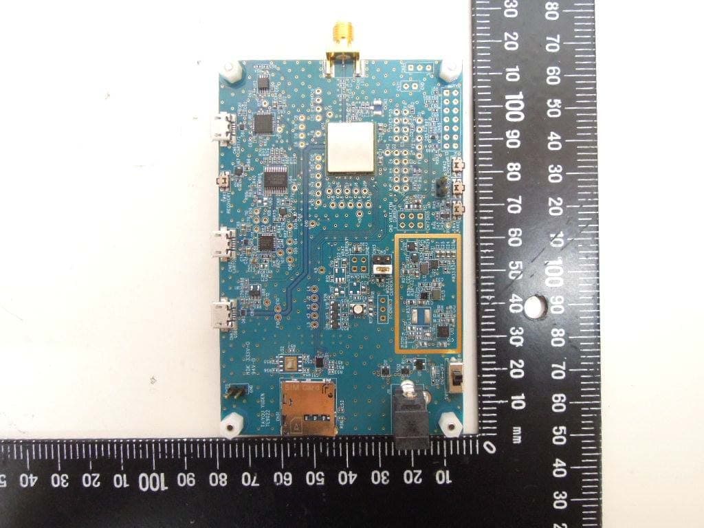
RYYCL5AD
Nov 17, 2020CatM1 Module
Equipment Class
PCB - PCS Licensed Transmitter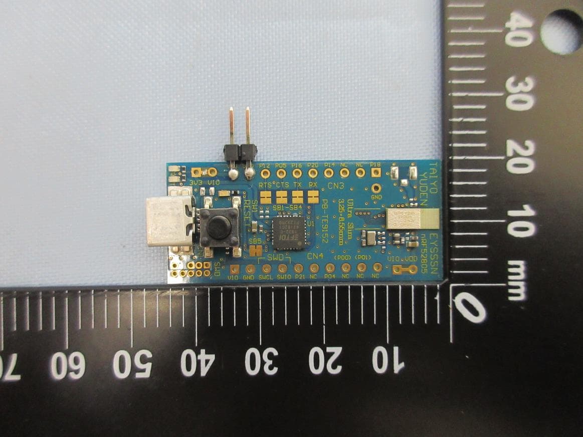
RYYEYSSSN
Nov 16, 2020Bluetooth low energy module
Equipment Class
DTS - Digital Transmission SystemRYYEYSPBN
Sep 07, 2020Bluetooth low energy/ ANT/ 802.15.4 Module
Equipment Class
DTS - Digital Transmission System
RYYEYSNCN
Feb 26, 2020Bluetooth low energy/ ANT/ 802.15.4 Module
Equipment Class
DTS - Digital Transmission System
RYYEYSNSN
Feb 16, 2020Bluetooth low energy/ ANT/ 802.15.4 Module
Equipment Class
DTS - Digital Transmission System